EP0225018B1 - Gerät zum Ausspritzen einer Mischung für dauerhafte Bügelfalten - Google Patents
Gerät zum Ausspritzen einer Mischung für dauerhafte Bügelfalten Download PDFInfo
- Publication number
- EP0225018B1 EP0225018B1 EP86307856A EP86307856A EP0225018B1 EP 0225018 B1 EP0225018 B1 EP 0225018B1 EP 86307856 A EP86307856 A EP 86307856A EP 86307856 A EP86307856 A EP 86307856A EP 0225018 B1 EP0225018 B1 EP 0225018B1
- Authority
- EP
- European Patent Office
- Prior art keywords
- applicator
- composition
- crease
- compressed air
- guidance means
- Prior art date
- Legal status (The legal status is an assumption and is not a legal conclusion. Google has not performed a legal analysis and makes no representation as to the accuracy of the status listed.)
- Expired
Links
- 239000011347 resin Substances 0.000 description 7
- 229920005989 resin Polymers 0.000 description 7
- 150000001875 compounds Chemical class 0.000 description 2
- 239000004744 fabric Substances 0.000 description 2
- 239000003562 lightweight material Substances 0.000 description 2
- 239000000463 material Substances 0.000 description 2
- 230000015572 biosynthetic process Effects 0.000 description 1
- 230000008878 coupling Effects 0.000 description 1
- 238000010168 coupling process Methods 0.000 description 1
- 238000005859 coupling reaction Methods 0.000 description 1
- 238000000151 deposition Methods 0.000 description 1
- 230000014759 maintenance of location Effects 0.000 description 1
- 239000002184 metal Substances 0.000 description 1
- 239000002991 molded plastic Substances 0.000 description 1
- 238000000465 moulding Methods 0.000 description 1
- 239000004033 plastic Substances 0.000 description 1
- 229920003023 plastic Polymers 0.000 description 1
- 229920002635 polyurethane Polymers 0.000 description 1
- 239000004814 polyurethane Substances 0.000 description 1
- 229920002379 silicone rubber Polymers 0.000 description 1
- 239000004945 silicone rubber Substances 0.000 description 1
- 239000004753 textile Substances 0.000 description 1
Images

Classifications
-
- A—HUMAN NECESSITIES
- A41—WEARING APPAREL
- A41D—OUTERWEAR; PROTECTIVE GARMENTS; ACCESSORIES
- A41D1/00—Garments
- A41D1/06—Trousers
- A41D1/10—Means for maintaining the crease
-
- B—PERFORMING OPERATIONS; TRANSPORTING
- B05—SPRAYING OR ATOMISING IN GENERAL; APPLYING FLUENT MATERIALS TO SURFACES, IN GENERAL
- B05C—APPARATUS FOR APPLYING FLUENT MATERIALS TO SURFACES, IN GENERAL
- B05C17/00—Hand tools or apparatus using hand held tools, for applying liquids or other fluent materials to, for spreading applied liquids or other fluent materials on, or for partially removing applied liquids or other fluent materials from, surfaces
- B05C17/005—Hand tools or apparatus using hand held tools, for applying liquids or other fluent materials to, for spreading applied liquids or other fluent materials on, or for partially removing applied liquids or other fluent materials from, surfaces for discharging material from a reservoir or container located in or on the hand tool through an outlet orifice by pressure without using surface contacting members like pads or brushes
- B05C17/015—Hand tools or apparatus using hand held tools, for applying liquids or other fluent materials to, for spreading applied liquids or other fluent materials on, or for partially removing applied liquids or other fluent materials from, surfaces for discharging material from a reservoir or container located in or on the hand tool through an outlet orifice by pressure without using surface contacting members like pads or brushes with pneumatically or hydraulically actuated piston or the like
Definitions
- This invention relates to an applicator, particularly for the formation of durable creases by application of a crease setting composition.
- the setting composition may be introduced into the formed creases, for example according to UK patent no. 1 603 252 or European published application no. 67 528.
- the creases are made durable by curing the composition.
- the applicator is operated by hand, and has a nozzle on one end of a cylinder.
- the composition filling the cylinder is compressed by a piston within the cylinder, and is forced through the nozzle.
- the piston is moved by the rotation of a rotary member mounted on the lower portion of the other end of the cylinder in response to movement along the creased line.
- the normal creasing composition cannot be employed since its viscosity is such that, although perfectly satisfactory for normal to heavyweight materials it can "strike through” to the front surface of lightweight materials.
- a different crease setting composition, or resin has to be employed which will not strike through.
- Such a resin is available but has a higher viscosity than the normally used composition. This means that more effort is needed to expel it through the nozzle. Since the driving force is obtained by pressure of a rotary member on the fabric of the trousers this can cause the fabric to ruck up or otherwise distort, thereby destroying the precision necessary to produce an accurate crease line.
- GB-A-2 158 159 (published after the priority date of this application) provides an applicator for crease setting composition which comprises an applicator body having at one end thereof a nozzle for applying the crease setting composition into a crease line and at the other end thereof an inlet for compressed air for forcing the composition out of the nozzle, and guidance means mounted beneath the body adapted, in use, to depend into the crease line so as to guide the applicator nozzle to cause it to deliver composition accurately into the crease.
- the means of expelling the crease setting composition is compressed air and no driving force need be generated by contact of driving wheels with the garment to be crease stabilised.
- GB-A-1 371 662 discloses a pneumatic dispensing tool in which air pressure is applied to a moveable cap under the control of a manual button. When the button is released the pressure on the cap is relieved via an exhaust port.
- EP-A-67 528 discloses a crease setting applicator which comprises an applicator body having at one end thereof a nozzle for applying crease setting composition into a crease line, and guidance means mounted beneath the body so as to guide the applicator nozzle and cause it to deliver composition accurately into the crease.
- the present invention seeks to provide an improved form of applicator in which the supply of compressed air is controlled automatically without there being need of a separate switch and associated electrical circuitry.
- the present invention is characterised in that at the other end of the applicator body there is an inlet for compressed air for forcing the composition out of the nozzle and in that the guidance means is operatively connected to a valve in the compressed air circuit such that when the guidance means contacts the garment to be treated pressure is applied to the composition by the compressed air and when the guidance means is removed from the garment to be treated the pressure is removed from the composition.
- the guidance means may be a pair of rollers or wheels similar to those on the device shown in European publication 67 528.
- the guide wheels are mounted on an axle in a block mounted for reciprocation within the applicator body.
- the distal end of the block carries a valve for the compressed air.
- the valve may be in the inlet of compressed air or, preferrably, in a connection from the interior of the applicator body to a vent for compressed air.
- the guide wheels contact the garment (or the support on which the garment is located) causing the block to move within its mounting and operate the compressed air valve thus causing pressure to be applied to the crease setting composition which will therefore be expelled from the nozzle.
- Removing the applicator from the garment has the opposite effect since the block will then, under the action of the compressed air, slide in the opposite direction thereby opening the valve and relieving the pressure from the composition.
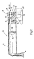
- the applicator illustrated is in some respects similar to the applicator illustrated in figure 1 of European patent no. 67 528 in that the applicator generally designated 10 comprises a reservoir 12 in the form of a moulded plastic cartridge body having a nozzle 14 which, in use, depends into the crease line of a garment being treated.
- the reservoir 12 may be in the form of a replaceable cartridge and contains a crease setting composition, for example a curable silicone rubber compound, or a curable polyurethane compound.
- the cartridge 12 is a slidable fit onto a shaped support block 16.
- the block 16 may be made from metal or, preferably, may be a plastics material moulding.
- Rotatable guide wheels 18 are mounted on an axle 20 held in a reciprocatable valve block 22.
- the block 22 is slidably mounted within the support block 16 and carries at its distal end a valve seat 24.
- the block 16 has an inlet 26 for compressed air which may have a suitable coupling for a compressed air line, leading into a central chamber 28 within the block and communicating with the area 30 behind a plunger 32. It will be appreciated that the crease setting composition is to the left of the plunger 32 as illustrated in the drawing, and that air pressure applied within the space 30 causes the plunger 32 to move to the left and expel composition from the nozzle 14.
- the cartridge or reservoir 12 is a slidable fit on the support block 16.
- 16 In order to locate and retain the cartridge and block 12, 16 together a further valve 34 is provided. This also operates under the pressure of compressed air within the chamber 28 and forces a spigot 36 downwardly through a corresponding hole in the cartridge 12 thereby retaining the cartridge 12 on the block 16.
- another form of mechanical retention for example a grubs- crew, could be employed but the pneumatic valve arrangement is convenient in that once the air pressure has been released (when the applicator is no longer in use) it is a very simple matter for the operator to remove and replace a spent cartridge 12.
- valve seat 24 on the reciprocatable block 22 cooperates with a valve passage 38 leading to an air vent 40, and the block 22 can slide between a position where the passage 38 is shut off to a position (illustrated) where the passage 38 is in communication with the vent 40.
- the applicator 10 is connected to an air supply and compressed air is led into the chamber 28.
- the pressure within the chamber 28 acting through the valve passage 38 forces downwardly the block 22 allowing the air to vent to atmosphere via the vent 40. Under these conditions there is insufficient pressure within the chamber 28 to force the plunger 32 along the cartridge and expel composition.
- the embodiment shown in figure 2 is generally the same as that shown in figure 1 and like numerals have been used for like parts. It differs in that the guidance means, instead of being wheels 18, comprise a blade or fin 42. The latter locates within the crease line of the garment being treated and accurately guides the applicator so that the nozzle 14 deposits a precise line of setting composition within the crease.
- the block 22 operates as described above.
- the apparatus of the invention provides a simple and elegant means of ensuring automatic control of the application of resin without requiring the operator independently to control the compressed air supply.
- the compressed air supply is left on and bringing the applicator to the garment ensures that composition is expelled exactly for the period when it is required and is shut off again when it is not required.
- the associated switch and electrical system including the solenoid may therefore be dipensed with leading to economies as well as more accurate control. Since the composition is turned off and on precisely when required savings in resin are made and more garments per cartridge may be treated.
Landscapes
- Engineering & Computer Science (AREA)
- Textile Engineering (AREA)
- Mechanical Engineering (AREA)
- Treatment Of Fiber Materials (AREA)
- Manufacture Of Iron (AREA)
- Medicinal Preparation (AREA)
- Nozzles (AREA)
Claims (7)
Priority Applications (1)
| Application Number | Priority Date | Filing Date | Title |
|---|---|---|---|
| AT86307856T ATE48956T1 (de) | 1985-10-29 | 1986-10-10 | Geraet zum ausspritzen einer mischung fuer dauerhafte buegelfalten. |
Applications Claiming Priority (2)
| Application Number | Priority Date | Filing Date | Title |
|---|---|---|---|
| GB8526656 | 1985-10-29 | ||
| GB858526656A GB8526656D0 (en) | 1985-10-29 | 1985-10-29 | Applicator for crease setting composition |
Publications (2)
| Publication Number | Publication Date |
|---|---|
| EP0225018A1 EP0225018A1 (de) | 1987-06-10 |
| EP0225018B1 true EP0225018B1 (de) | 1989-12-27 |
Family
ID=10587422
Family Applications (1)
| Application Number | Title | Priority Date | Filing Date |
|---|---|---|---|
| EP86307856A Expired EP0225018B1 (de) | 1985-10-29 | 1986-10-10 | Gerät zum Ausspritzen einer Mischung für dauerhafte Bügelfalten |
Country Status (5)
| Country | Link |
|---|---|
| US (1) | US4778299A (de) |
| EP (1) | EP0225018B1 (de) |
| AT (1) | ATE48956T1 (de) |
| DE (1) | DE3667755D1 (de) |
| GB (1) | GB8526656D0 (de) |
Cited By (1)
| Publication number | Priority date | Publication date | Assignee | Title |
|---|---|---|---|---|
| CN105057181A (zh) * | 2015-07-31 | 2015-11-18 | 重庆市惠美实业有限公司 | 胶鞋底自动涂胶装置 |
Families Citing this family (17)
| Publication number | Priority date | Publication date | Assignee | Title |
|---|---|---|---|---|
| GB2219527A (en) * | 1988-06-09 | 1989-12-13 | Wool Dev Int | Automatically controlled applicator heads |
| US5395032A (en) * | 1989-02-22 | 1995-03-07 | Ing. Erich Pfeiffer Gmbh & Co. Kg | Dispenser for media |
| US5013378A (en) * | 1989-11-30 | 1991-05-07 | Farah Incorporated | Pleated trouser crease-forming method and machine improvements therefor |
| JP2772188B2 (ja) * | 1992-01-23 | 1998-07-02 | 武蔵エンジニアリング株式会社 | 液体ディスペンサーのシリンジ用プランジャー |
| US6231713B1 (en) * | 1999-05-24 | 2001-05-15 | Paul L. Iams | Method and apparatus for forming a permanent crease in a cloth |
| GB9912776D0 (en) * | 1999-06-02 | 1999-08-04 | Clantex Ltd | Improvements relating to cartridges for dispensingf fluent material |
| US6929161B2 (en) * | 1999-06-02 | 2005-08-16 | Clantex Limited | Cartridges for dispensing fluent material |
| KR20030032624A (ko) * | 2001-10-19 | 2003-04-26 | 주식회사 삼호특수 | 회동지지수단을 갖는 전동 코킹건 |
| GB0410839D0 (en) * | 2004-05-14 | 2004-06-16 | Glaxo Group Ltd | Novel device |
| US9139952B2 (en) * | 2012-03-08 | 2015-09-22 | James Hangley | Applicator for applying resin to a precreased piece of fabric and method of the same |
| GB201510784D0 (en) | 2015-06-19 | 2015-08-05 | Supercrease Ltd | Apparatus, material and method of applying the same to garments |
| US20210007430A1 (en) * | 2018-04-06 | 2021-01-14 | Supercrease Limited | Apparatus and a Method For The Application Of A Fluid Material To A Garment |
| GB201900257D0 (en) * | 2019-01-08 | 2019-02-27 | Supercrease Ltd | Improvements to apparatus for the application of resin along a crease line |
| GB202000267D0 (en) * | 2020-01-09 | 2020-02-26 | Supercrease Ltd | Improved cartridge for dispensing resin |
| GB202000594D0 (en) * | 2020-01-15 | 2020-02-26 | Supercrease Ltd | Resin for use in setting a crease in a garment |
| CN115090494B (zh) * | 2022-07-15 | 2023-04-11 | 神封胶业(南京)有限公司 | 一种带密封件的有机硅密封胶胶枪 |
| GB202219272D0 (en) * | 2022-12-20 | 2023-02-01 | Supercrease Ltd | Improvements to apparatus for the application of resin along a crease line of a garment |
Family Cites Families (10)
| Publication number | Priority date | Publication date | Assignee | Title |
|---|---|---|---|---|
| US3258176A (en) * | 1964-09-24 | 1966-06-28 | Zenith Radio Corp | Pneumatic glue dispenser |
| FR1448519A (fr) * | 1964-09-30 | 1966-01-28 | Pyles Ind Inc | Pistolet dispensateur de fluides |
| US3687102A (en) * | 1969-12-29 | 1972-08-29 | Elmer M Dunn | Apparatus for treating fabric items |
| GB1371662A (en) * | 1971-11-01 | 1974-10-23 | Spotnails | Pneumatically powered dispensing tool |
| US3813012A (en) * | 1973-03-12 | 1974-05-28 | Prod Res & Chem Corp | Air powered sealant dispenser, including flexible tubular conduits as valve means |
| US4182264A (en) * | 1977-02-21 | 1980-01-08 | I.W.S. Nominee Company Limited | Apparatus for applying a crease retaining coating in a preformed crease |
| EP0059413B1 (de) * | 1981-02-24 | 1985-02-06 | Clantex Limited | Spender für fliessfähige Materialien |
| ZA823183B (en) * | 1981-05-16 | 1983-03-30 | Wool Dev Int | Improved applicator |
| DE3467286D1 (en) * | 1983-09-01 | 1987-12-17 | Wool Dev Int | Fluid dispensing apparatus |
| GB2158159B (en) * | 1984-04-17 | 1987-09-30 | Dynic Corp | Applicator for crease-setting composition |
-
1985
- 1985-10-29 GB GB858526656A patent/GB8526656D0/en active Pending
-
1986
- 1986-10-10 DE DE8686307856T patent/DE3667755D1/de not_active Expired - Fee Related
- 1986-10-10 AT AT86307856T patent/ATE48956T1/de not_active IP Right Cessation
- 1986-10-10 EP EP86307856A patent/EP0225018B1/de not_active Expired
- 1986-10-28 US US06/924,197 patent/US4778299A/en not_active Expired - Lifetime
Cited By (1)
| Publication number | Priority date | Publication date | Assignee | Title |
|---|---|---|---|---|
| CN105057181A (zh) * | 2015-07-31 | 2015-11-18 | 重庆市惠美实业有限公司 | 胶鞋底自动涂胶装置 |
Also Published As
| Publication number | Publication date |
|---|---|
| ATE48956T1 (de) | 1990-01-15 |
| EP0225018A1 (de) | 1987-06-10 |
| US4778299A (en) | 1988-10-18 |
| GB8526656D0 (en) | 1985-12-04 |
| DE3667755D1 (de) | 1990-02-01 |
Similar Documents
| Publication | Publication Date | Title |
|---|---|---|
| EP0225018B1 (de) | Gerät zum Ausspritzen einer Mischung für dauerhafte Bügelfalten | |
| US3854648A (en) | Air operated fastener driving tool, especially for tacks | |
| US5188047A (en) | Production of circular seams on a workpiece | |
| US4505410A (en) | Fluid applicator for treating garments | |
| US2280658A (en) | Vacuum pickup | |
| US4448808A (en) | Method for preparing pattern piece | |
| US4485736A (en) | Ink-dispensing system and method for silk-screen printing having squeegee stroke movement counter | |
| US4004511A (en) | Printing apparatus | |
| US4756170A (en) | Applicator for crease-setting composition | |
| CA2048918A1 (en) | Air brush set | |
| WO2019193345A1 (en) | Apparatus and a method for the application of a fluid material to a garment | |
| EP1185379B1 (de) | Verbesserungen in einer kombination von patrone und düse zur abgabe fliessfähigen materials | |
| CA1172030A (en) | Apparatus for marking a rotating tire | |
| GB2582204A (en) | Improvements to apparatus and a method for the application of resin along one or more crease lines | |
| US3657053A (en) | Mechanism for rigidifying a collapsible object | |
| US4821940A (en) | T-nut insertion machine | |
| US4191793A (en) | Method of forming a durable crease | |
| US2875684A (en) | Hide stamper | |
| JPH0784702B2 (ja) | 折り目固定剤用アプリケ−タ | |
| US4940184A (en) | Spraying apparatus with speed indicating assembly | |
| US2280204A (en) | Method and means for removing flash | |
| US2863383A (en) | Printing machine | |
| US3298048A (en) | Machine for roughening the margin of the bottom of a shoe | |
| GB2199774A (en) | Applicator for crease setting compositions | |
| CA1105220A (en) | Ejection of molded materials |
Legal Events
| Date | Code | Title | Description |
|---|---|---|---|
| PUAI | Public reference made under article 153(3) epc to a published international application that has entered the european phase |
Free format text: ORIGINAL CODE: 0009012 |
|
| AK | Designated contracting states |
Kind code of ref document: A1 Designated state(s): AT BE CH DE FR GB IT LI NL SE |
|
| 17P | Request for examination filed |
Effective date: 19871127 |
|
| 17Q | First examination report despatched |
Effective date: 19881121 |
|
| GRAA | (expected) grant |
Free format text: ORIGINAL CODE: 0009210 |
|
| AK | Designated contracting states |
Kind code of ref document: B1 Designated state(s): AT BE CH DE FR GB IT LI NL SE |
|
| REF | Corresponds to: |
Ref document number: 48956 Country of ref document: AT Date of ref document: 19900115 Kind code of ref document: T |
|
| REF | Corresponds to: |
Ref document number: 3667755 Country of ref document: DE Date of ref document: 19900201 |
|
| ITF | It: translation for a ep patent filed | ||
| ET | Fr: translation filed | ||
| PLBE | No opposition filed within time limit |
Free format text: ORIGINAL CODE: 0009261 |
|
| STAA | Information on the status of an ep patent application or granted ep patent |
Free format text: STATUS: NO OPPOSITION FILED WITHIN TIME LIMIT |
|
| 26N | No opposition filed | ||
| PGFP | Annual fee paid to national office [announced via postgrant information from national office to epo] |
Ref country code: SE Payment date: 19910927 Year of fee payment: 6 |
|
| PGFP | Annual fee paid to national office [announced via postgrant information from national office to epo] |
Ref country code: FR Payment date: 19911007 Year of fee payment: 6 |
|
| PGFP | Annual fee paid to national office [announced via postgrant information from national office to epo] |
Ref country code: AT Payment date: 19911015 Year of fee payment: 6 |
|
| PGFP | Annual fee paid to national office [announced via postgrant information from national office to epo] |
Ref country code: CH Payment date: 19911025 Year of fee payment: 6 |
|
| ITTA | It: last paid annual fee | ||
| PGFP | Annual fee paid to national office [announced via postgrant information from national office to epo] |
Ref country code: NL Payment date: 19911031 Year of fee payment: 6 Ref country code: DE Payment date: 19911031 Year of fee payment: 6 |
|
| PGFP | Annual fee paid to national office [announced via postgrant information from national office to epo] |
Ref country code: BE Payment date: 19911211 Year of fee payment: 6 |
|
| PG25 | Lapsed in a contracting state [announced via postgrant information from national office to epo] |
Ref country code: AT Effective date: 19921010 |
|
| PG25 | Lapsed in a contracting state [announced via postgrant information from national office to epo] |
Ref country code: SE Effective date: 19921011 |
|
| PG25 | Lapsed in a contracting state [announced via postgrant information from national office to epo] |
Ref country code: LI Effective date: 19921031 Ref country code: CH Effective date: 19921031 Ref country code: BE Effective date: 19921031 |
|
| BERE | Be: lapsed |
Owner name: DYNIC CORP. Effective date: 19921031 Owner name: WOOL DEVELOPMENT INTERNATIONAL LTD Effective date: 19921031 |
|
| PG25 | Lapsed in a contracting state [announced via postgrant information from national office to epo] |
Ref country code: NL Effective date: 19930501 |
|
| NLV4 | Nl: lapsed or anulled due to non-payment of the annual fee | ||
| PG25 | Lapsed in a contracting state [announced via postgrant information from national office to epo] |
Ref country code: FR Effective date: 19930630 |
|
| REG | Reference to a national code |
Ref country code: CH Ref legal event code: PL |
|
| PG25 | Lapsed in a contracting state [announced via postgrant information from national office to epo] |
Ref country code: DE Effective date: 19930701 |
|
| REG | Reference to a national code |
Ref country code: FR Ref legal event code: ST |
|
| EUG | Se: european patent has lapsed |
Ref document number: 86307856.4 Effective date: 19930510 |
|
| REG | Reference to a national code |
Ref country code: GB Ref legal event code: IF02 |
|
| PGFP | Annual fee paid to national office [announced via postgrant information from national office to epo] |
Ref country code: GB Payment date: 20041006 Year of fee payment: 19 |
|
| PG25 | Lapsed in a contracting state [announced via postgrant information from national office to epo] |
Ref country code: IT Free format text: LAPSE BECAUSE OF NON-PAYMENT OF DUE FEES;WARNING: LAPSES OF ITALIAN PATENTS WITH EFFECTIVE DATE BEFORE 2007 MAY HAVE OCCURRED AT ANY TIME BEFORE 2007. THE CORRECT EFFECTIVE DATE MAY BE DIFFERENT FROM THE ONE RECORDED. Effective date: 20051010 Ref country code: GB Free format text: LAPSE BECAUSE OF NON-PAYMENT OF DUE FEES Effective date: 20051010 |
|
| GBPC | Gb: european patent ceased through non-payment of renewal fee |
Effective date: 20051010 |