EP0225105B1 - Diffuseur de lumière photographique - Google Patents
Diffuseur de lumière photographique Download PDFInfo
- Publication number
- EP0225105B1 EP0225105B1 EP86308964A EP86308964A EP0225105B1 EP 0225105 B1 EP0225105 B1 EP 0225105B1 EP 86308964 A EP86308964 A EP 86308964A EP 86308964 A EP86308964 A EP 86308964A EP 0225105 B1 EP0225105 B1 EP 0225105B1
- Authority
- EP
- European Patent Office
- Prior art keywords
- support rod
- light diffuser
- frame
- photographic light
- panel
- Prior art date
- Legal status (The legal status is an assumption and is not a legal conclusion. Google has not performed a legal analysis and makes no representation as to the accuracy of the status listed.)
- Expired
Links
- 239000004744 fabric Substances 0.000 claims description 5
- 239000004677 Nylon Substances 0.000 claims description 4
- 239000000463 material Substances 0.000 claims description 4
- 229920001778 nylon Polymers 0.000 claims description 4
- BQCADISMDOOEFD-UHFFFAOYSA-N Silver Chemical compound [Ag] BQCADISMDOOEFD-UHFFFAOYSA-N 0.000 claims description 3
- 229910052709 silver Inorganic materials 0.000 claims description 3
- 239000004332 silver Substances 0.000 claims description 3
- 230000001419 dependent effect Effects 0.000 claims 1
- 230000000694 effects Effects 0.000 description 8
- 238000010276 construction Methods 0.000 description 2
- 230000004075 alteration Effects 0.000 description 1
- 230000005540 biological transmission Effects 0.000 description 1
- 230000007423 decrease Effects 0.000 description 1
- 230000000994 depressogenic effect Effects 0.000 description 1
- 238000005286 illumination Methods 0.000 description 1
- 238000003780 insertion Methods 0.000 description 1
- 230000037431 insertion Effects 0.000 description 1
- 230000002452 interceptive effect Effects 0.000 description 1
- 238000012986 modification Methods 0.000 description 1
- 230000004048 modification Effects 0.000 description 1
- 238000006467 substitution reaction Methods 0.000 description 1
- 239000012780 transparent material Substances 0.000 description 1
Images

Classifications
-
- G—PHYSICS
- G03—PHOTOGRAPHY; CINEMATOGRAPHY; ANALOGOUS TECHNIQUES USING WAVES OTHER THAN OPTICAL WAVES; ELECTROGRAPHY; HOLOGRAPHY
- G03B—APPARATUS OR ARRANGEMENTS FOR TAKING PHOTOGRAPHS OR FOR PROJECTING OR VIEWING THEM; APPARATUS OR ARRANGEMENTS EMPLOYING ANALOGOUS TECHNIQUES USING WAVES OTHER THAN OPTICAL WAVES; ACCESSORIES THEREFOR
- G03B15/00—Special procedures for taking photographs; Apparatus therefor
- G03B15/02—Illuminating scene
- G03B15/06—Special arrangements of screening, diffusing, or reflecting devices, e.g. in studio
Definitions
- the present invention relates to a light diffuser for use with light sources in photography. Diffused or indirect lighting is used in both still and motion picture type photography. To achieve an indirect, soft type lighting effect it is desirable to first either directly or indirectly pass the light through a semi-transparent material to break up and diffuse the light rays. Such lighting is generally produced by light sources which are remote from the camera.
- Each particular area to be lighted will dictate the type and intensity of light that will be needed. In some situations direct light from the light source without any alteration may be required. In other situations direct light may be too strong or cast overly distinct shadows in which case a more diffuse light may be more desirable. In still other cases an even more indirect diffuse light may be needed to create the proper lighting effect. It is also important to have a great deal of uniformity in the lighting to assist the photographer in properly lighting the subject.
- the light diffuser should also be capable of being used with almost any type of light source and mounting bracket for the light source. It is also desirable to have a light diffuser that is a compact, self-contained unit that is easy to position and use.
- US-A-3 851 164 discloses a light directing device in the form of an umbrella-like structure arranged to function as a reflector and including a support rod pivoted to the axial shaft to which the ribs of the umbrella are pivoted.
- the support rod enters the open mouth of the umbrella.
- This device is not a light diffuser. It is simply a light reflector.
- the passage of the support rod through the open mouth of the umbrella prevents any form of diffusing screen from being placed across the mouth of the umbrella.
- the device cannot be tilted to project light upwardly, such orientation being prevented by the support rod which would come against the edge of the umbrella structure.
- JP-A-60-104 929 discloses also an umbrella-like reflector the mouth of which is covered by a translucent screen.
- the light source is arranged behind the reflector and projects all its light towards the translucent screen.
- the device cannot provide fully even illumination because since the light source is behind the reflector the reflecting surface can reflect forwardly only the small proportion of light reflected back towards it by the translucent screen.
- the reflecting surface receives no light directly from the light source.
- the device of the present invention makes the most efficient use of the light from the light source and the most even distribution of the light through a diffusing screen while allowing the device to be tilted over a wide vertical angle from a downward orientation to an upward orientation.
- a photographic light diffuser comprising a support rod for attaching a light source and a rod of a floor stand, a frame structure connected to a first end of said support rod frame extending radially away from said support rod to form a dished structure around said support rod, said frame structure defining an opening around said support rod, a second end of said support rod terminating substantially at said opening defined by said frame structure, a cover positioned on said frame structure, said cover having a reflective surface and being positioned on the support structure so that said reflective surface faces said support rod is characterised by a translucent panel connected to said cover, said translucent cover being disposed to cover said opening defined by said frame structure, said translucent panel and said cover enclosing said support rod and said frame structure and a closable slit in said cover being substantially parallel to the support rod to provide access to the interior of said light diffuser and for receiving said rod of a floor stand for mounting said light diffuser in an elevated position.
- the ribs of the frame are covered by a reflective panel with a reflective silver color interior and a black interior.
- a translucent panel of white nylon or other suitable material is positioned to cover the opening defined by the frame. The translucent panel can be releasably secured to the reflective panel.
- a closeable opening is provided in the reflective panel to provide access to the interior of the diffuser for mounting a light source.
- the light source mounted inside the diffuser can either be aimed directly at the translucent panel or first reflected off the reflective panel to diffuse the light even more before it passes through the translucent panel.
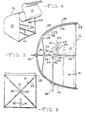
- the present invention relates to photographic light diffuser 10 as shown in the attached figures.
- the diffuser 10 generally consists of a support rod 12, a frame assembly 14 and a cover 15.
- the cover has a translucent panel 16 and a reflective panel 18.
- the support rod 12 has a first end 20 and a second end 22 and serves to support the frame assembly 14.
- the frame assembly 14 is connected to the first end 20 of the support rod 12 and forms a substantialiy parabolic shaped structure around the support rod 12.
- the frame assembly 14 can be in a closed position as shown in Fig. 3 or in an open position as shown in Figs. 1 and 2. When the frame 14 is in the open position it defines an opening around the support rod 12.
- the opening defined by the frame 14 is substantially square or rectangular and the second end 22 of the support rod 12 is located at substantially the place defined by the opening and the second end 22 is positioned in substantially the center of the opening.
- the frame assembly 14 is comprised of a plurality of ribs 23 having a first end 24 and a second end 25.
- the first ends 24 of the ribs 23 are pivotally connected to the first end 20 of the support rod 12.
- a corresponding plurality of stretchers 26 are connected to the ribs 23.
- Each of the stretchers 26 has a first end 28 and a second end 30.
- the first ends 28 of the stretchers 26 are pivotally connected to ribs 23 and substantially the midpoint of the ribs 23.
- the second end 30 of the stretchers 26 are pivotally and slideably connected to the support rod 12 by a runner 32 that is slideably positioned on the support rod 12.
- the runner 32 can be advanced along the support rod 12 to move the stretchers to a position where the collapsible frame 14 is in an open position.
- the second ends 25 of the ribs 23 are radially spaced apart from the support rod 12 and define a substantially parabolic shaped structure.
- the second ends 25 of the ribs 23 also define a substantially square or rectangular opening around the support rod 12.
- a retractable lock mechanism 34 as typically found on umbrellas is positioned within and extends from the support rod 12 near its first end 20.
- the runner 32 is advanced along the support rod 12 in a direction towards the first end 20.
- the lock mechanism 34 retracts into the rod 12 as the runner 32 passes over the lock mechanism.
- the lock mechanism 34 extends from the support rod 12 and engages the runner 32.
- the lock mechanism 34 thereby holds the runner 32 in this position on the support rod and retains the frame assembly 14 in the open position.
- the lock mechanism is depressed into the support rod 12 and this allows the runner 32 to be advanced in a direction towards the second end 22 of the support rod 12.
- the frame 14 is covered with a translucent panel 18.
- the reflective panel contains a tip cap 36 that is disposed for receiving the first end 20 of the support 12.
- the tip cap 36 acts to attach the reflective panel to the support rod 12.
- the outer periphery of the reflective panel 18 is fastened to the second end 25 of each of the ribs 23.
- the reflective panel 18 is supported by the ribs 23 of the frame 14 and the ribs hold the reflective panel in a substantially parabolic shape.
- the tip cap 36 is disposed in substantially the center of the reflective panel 18.
- the reflective panel 18 substantially covers the substantially parabolic shaped frame 14.
- the interior surface 38 of the reflective panel 18 is reflective. Silver colored nylon or other similarly reflective surface fabrics may be used for the interior surface 38 of the reflective panel 18.
- the outer surface 39 of the reflective panel 18 is black or another dark color to retard light transmission through the reflective panel 18.
- the substantially square or rectangular opening defined by the frame 14 is covered with a translucent fabric panel 16 such as white nylon or other suitably translucent material.
- the translucent panel 16 is normally sewn to one side of the substantially square or rectangular opening.
- the other sides of the translucent panel 16 are provided with a releasable attachment means 40 to secure the other three edges of the translucent panel 16 to the surfaces of the reflective panel 18 adjacent the opening defined by the frame 14.
- Velcro or other suitable releasable attachment means can be used to secure the translucent panel 16 to the reflective panel 18.
- the releasable attachment means 40 can be used on all sides of the translucent panel 16 so that any side of the translucent panel can be removed from the reflective panel and so that the entire translucent panel 16 can be removed from engagement with reflective panel and removed from the opening defined by the frame 14.
- the diffuser 10 forms an enclosed chamber 37.
- the second end 22 of the support 12 is positioned adjacent the translucent panel and within the enclosed chamber 37.
- the closeably opening 41 normally extends from the substantially square opening defined by the frame 14 along the reflective panel 18 in a direction towards the first end 20 of the support rod 12.
- the closeable opening 41 normally extends at least one-half the distance from the opening defined by the frame 14 to the point where the first end 20 of the support rod 12 passes through the reflective panel 18.
- the opening 41 is also normally disposed to be substantially parallel to the support rod 12.
- a slit 41 of almost any length and position can be used in the reflective panel 18 as long as the opening should be sufficiently large to allow the insertion of a hooded light source 46 such as shown in Fig. 5.
- the closeable slit 41 provides access to the interior of the diffuser 10 and allows the diffuser to be positioned in almost any desired angular position on a standard support stand 50 that is used to support the hood light source 46. It has been found that a zipper 42 works particularly well as the closing means for the closeable slit 41. In particular, a zipper that is closeably from each end is useful as this allows the slit 41 to be closed around the support stand 50 regardless of where the support stand 50 is positioned in the slit 41. When the diffuser 10 is in the collapsed position, it resembles the configuration shown in Fig.
- the ribs 23 and the stretchers 26 of the frame 14 are positioned adjacent the support rod 12.
- the reflective panel 18 and the translucent panel 16 of the cover 15 can also be folded to be substantially adjacent the support rod 12 to provide a compact unit for easy storage and transportation.
- the runner 32 is advanced along the support rod 12 in a direction towards the first end 20 of the support rod.
- the ribs 23 and stretchers 26 of the frame 14 extend radially away from the support rod 12 to form a substantially parabolic shaped frame configuration.
- the translucent fabric panel 16 and the reflective panel 18 are held in substantially taut position so that there is essentially no sag or loose fabric on the diffuser 10.
- a light source 46 can be placed within the interior chamber 37 through closeable slit 41 in the cover 15.
- the light source 46 can be adjustably mounted on the support rod 12.
- the light source can include a reflector 47 that can be used to direct the light in the desired direction.
- the reflector can be removable and when removed the light from the light source will not be directed in any direction.
- the diffuser 10 can be mounted on the support stand 50 to elevate the diffuser above the ground and allow vertical and rotational adjustment of the diffuser.
- the light source 46 and the stand 50 are mounted to the support rod 12 by an adjustable mounting block 52.
- the frictional adjustment knobs 54, 56 and 58 By loosening and retightening the frictional adjustment knobs 54, 56 and 58, the light 46 in the stand 50 can be moved back and forth along the support rod 12.
- both the vertical height and the rotation of the light 46 in the stand 50 can be adjusted.
- the adjustments can be made by reaching through closeable slit 41 or by releasing the translucent panel 16 from the reflective panel 18 and reaching into the opening formed by the frame assembly 14.
- the opening in the diffuser 10 is closed to again form an enclosed chamber 27. Closing the diffuser 10 prevents any stray light from interfering with the desired lighting effect produced by the light diffuser.
- the light source 46 can be equipped with either a strobe-type light 60, a conventional light bulb 62 or both types of lights. Although a mounting block 52 has been shown to mount the lighting source 46, it should be understood that almost any type of mounting bracket for a light source can be used with the diffuser of the present invention. This allows the diffuser 10 to be used almost universally with any type of mounting bracket for the light source.
- the light source 46 is shown aimed directly at the translucent panel 16 of the cover 15.
- the light from the light source 46 passes directly through the translucent panel and onto the subject that is to be photographed.
- a larger pattern of light is emitted from the diffuser 10 as the light source 46 is moved in a direction away from the translucent panel 16 along the support rod 12. The further the light source is spaced apart from the translucent panel 16 the more the light can radially disperse to fill a larger portion of the translucent panel.
- the position of the light source and the diffuser 10 can be used to vary the pattern of the light emitted from the diffuser onto the subject or object to be photographed. Since the translucent panel 16 extends across the substantially square or rectangular opening defined by the frame assembly 14, a substantially square or rectangular pattern of diffused light is emitted from the diffuser 10. As the support rod 12 is the only structure that is positioned between the light source 46 and the translucent panel 16, there is almost no interference with the light that is emitted from the diffuser. Since the light source 46 is positioned in substantially the center of the diffuser 10, the intensity of the light is strongest around the center of the translucent panel 16 adjacent to the support rod 12. The intensity from the light source decreases progressively as it moves from the center of the translucent panel 16 towards the outer periphery of the translucent panel.
- the user can position the light source, as shown in phantom in Fig. 5, to be directed towards the reflective panel 18.
- the light is reflected on the reflective panel 18 and then passes through the translucent front panel 18. Reflecting the light on the reflective panel 18 breaks up the light pattern from the light source 46 and results in a much softer type of light being emitted from the translucent panel 16 of the diffuser 10.
- Positioning the light source 46 so that the light strikes the reflective panel 18 before being emitted from the diffuser 10 allows the photographer a means for easily adjusting the effect of the light source upon the subject that is to be photographed.
- a larger pattern of light is emitted from the diffuser 10 becomes larger as the light source 46 is moved in a direction towards the translucent panel 16 along the support rod 12, with the light source still directed towards the reflective panel 18.
- the position of the light source 46 in the diffuser 10 can be used to vary the pattern of light reflected from the reflective panel 18 and the pattern of light that is emitted from the translucent panel 16 onto the object that is to be photographed.
- the opening defined by the frame assembly 14 is substantially square or rectangular
- the light that is reflected from the reflective panel 18 will form a substantially square or rectangular pattern on the translucent panel 16.
- the light that is emitted from the diffuser 10 will be in a well-defined controlled pattern that makes it easier for the photographer to produce the desired lighting effect on the object that is to be photographed.
- the reflected mode so much light is reflected that the light substantially fills the translucent panel with light that is emitted from the diffuser.
- the light is reflected from so many different angles that the light source and support rod in the diffuser does not disrupt the substantially uniform level of reflected light that is emitted from the diffuser.
- the light source 46 directs light in all directions and there is both direct and reflected light that is emitted from the translucent panel.
- the diffuser has its greatest output of light as there is both direct and reflected light emitted from the diffuser.
- the light that is emitted from the diffuser 10 is very uniform with essentially no dark spots or shadows. This uniformity of light is present whether the light source is positioned in the direct, reflected or direct and reflected mode. The uniformity of the light makes it easier for the photographer to set up the lights to achieve the desired type of lighting on the subject that is to be photographed.
- the diffuser 10 can either be removed from the light source 48 and used with another light source or simply collapsed, folded and stored until needed again.
- the diffuser 10 is a complete unit that is easily opened and collapsed without the use of a special tool. It is a very simple operation to open or close the diffuser and requires a minimum of time. Also the light source can be easily mounted on the support rod through the closeable opening.
- the openable translucent panel also makes it very easy to makes adjustments to the light source to obtain the desired lighting effect on the subject to be photographed.
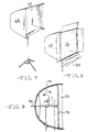
- Figs. 7, 8 and 9 show another embodiment of the photographic light diffuser of the present invention.
- This embodiment of the diffuser 65 is substantially similar in construction and use as the previously discussed diffuser 10.
- dark panels 70 extend beyond the translucent panel 72 positioned in the opening defined by the frame structure 74 of the light diffuser 65.
- the dark panels are an extension of the reflective panels 73 where the reflective surface has been removed from the interior of the reflective panel.
- the translucent panel 72 is recessed slightly into the opening defined by the frame structure 74 so that the dark panel 70 formed in the reflective panel 73 extend beyond the translucent panel 72.
- the translucent panel is inset from the ends of the ribs 76 of the frame structure 74, a distance that is about from 2% to about 10% of the length of the support rod 78 for the light diffuser 65.
- the dark panels can be attachable separate pieces to the ends of the ribs 76 of the frame structure 74 as shown in Fig. 9.
- the dark panel 70 would extend beyond the ends of the ribs 76 and the translucent panel 72 would be positioned in the opening in the frame structure 74 at the ends of the ribs 76.
- the dark panels can be pivotally connected to the ribs 76 so that the dark panel 70 can be pivoted towards and away from the translucent panel 72.
- the dark panels can also be designed to be removably secured to the ends of the ribs 76.
- the dark panels could be positioned on the ends of the ribs only when the dark panels were required to produce the desired lighting effect.
- these panels can be made of any suitable non-reflective black material.
- the dark panels can be used to further control the pattern of light that is emitted from the light diffuser 65.
- the dark panels 70 When the dark panels 70 are an extension of the reflective panel 73 positioned on the frame structure 74, the dark panels effectively limit the area of light emitting from the light diffuser 65 to substantially square or rectangular area defined by the panels.
- the dark panels When the dark panels are hingedly connected to the ends of the ribs 76 on the frame structure 74, the dark panels can be angled towards and away from the translucent panel 72 to further control the shape of the light emitted from the light diffuser 65. If the dark panels 70 are angled towards the translucent panel 72, this will act to reduce the area of light emitted from the light diffuser. When the dark panels 70 are angled away from the translucent panel 72, this will allow a larger area of light to be emitted from the light diffuser 65.
- the light source 82 can be positioned in the interior of the light diffuser 65 to direct light directly through the translucent panel 72 or to direct light against the reflective panel 73 so that the light is reflected and further diffused before passing through the translucent panel 72.
- the light diffuser 65 acts in the sme manner as the previously discussed light diffuser 10.
Landscapes
- Physics & Mathematics (AREA)
- General Physics & Mathematics (AREA)
- Securing Globes, Refractors, Reflectors Or The Like (AREA)
- Stroboscope Apparatuses (AREA)
- Mirrors, Picture Frames, Photograph Stands, And Related Fastening Devices (AREA)
Claims (24)
Applications Claiming Priority (2)
| Application Number | Priority Date | Filing Date | Title |
|---|---|---|---|
| US801217 | 1985-11-25 | ||
| US06/801,217 US4757425A (en) | 1985-11-25 | 1985-11-25 | Photographic light diffuser |
Publications (3)
| Publication Number | Publication Date |
|---|---|
| EP0225105A2 EP0225105A2 (fr) | 1987-06-10 |
| EP0225105A3 EP0225105A3 (en) | 1987-10-14 |
| EP0225105B1 true EP0225105B1 (fr) | 1991-01-02 |
Family
ID=25180493
Family Applications (1)
| Application Number | Title | Priority Date | Filing Date |
|---|---|---|---|
| EP86308964A Expired EP0225105B1 (fr) | 1985-11-25 | 1986-11-17 | Diffuseur de lumière photographique |
Country Status (4)
| Country | Link |
|---|---|
| US (1) | US4757425A (fr) |
| EP (1) | EP0225105B1 (fr) |
| CA (1) | CA1268451A (fr) |
| DE (1) | DE3676464D1 (fr) |
Families Citing this family (79)
| Publication number | Priority date | Publication date | Assignee | Title |
|---|---|---|---|---|
| DE8702694U1 (de) * | 1987-02-21 | 1987-04-23 | Bron Elektronik AG, Allschwil, Basel | Reflektor für fotografische Lichtquellen |
| US4998189A (en) * | 1989-05-04 | 1991-03-05 | Giles Guggemos | Collapsible reflector unit for display structures |
| US5077640A (en) * | 1990-08-13 | 1991-12-31 | Butler Jr C Tyler | Photographic lighting apparatus |
| US5113207A (en) * | 1990-12-04 | 1992-05-12 | Huebner International, Inc. | Apparatus and method for photographing reflective objects |
| US5154503A (en) * | 1991-03-11 | 1992-10-13 | F. J. Westcott Company | Photographic light modifier |
| USD342273S (en) | 1992-02-27 | 1993-12-14 | Quest Productions, Inc. | Light diffuser for electronic flash |
| JP2979939B2 (ja) * | 1993-12-27 | 1999-11-22 | 株式会社日立製作所 | 二次電池システムの運転方法 |
| DE19618434C1 (de) * | 1996-05-08 | 1997-11-20 | Briese Hans Werner | Reflektor |
| US6377663B1 (en) * | 1997-01-03 | 2002-04-23 | Ncr Corporation | Call management system and associated method for a local telephone circuit |
| EP0961161B1 (fr) * | 1998-05-25 | 2003-12-17 | Ross M. Horowitz | Système modulaire pour poser et éclairer des objets en photographie |
| US6106125A (en) | 1998-09-02 | 2000-08-22 | Finn; Bruce L. | Foldable modular light diffusion box |
| US7204617B1 (en) * | 1998-09-02 | 2007-04-17 | Bruce L. Finn | Foldable modular light diffusion box |
| US6719434B1 (en) | 1998-09-02 | 2004-04-13 | Bruce L. Finn | Foldable light diffusion box with frame assembly |
| US6491405B1 (en) | 1999-11-20 | 2002-12-10 | John E. Shirilla | Photographic umbrella with reflective and diffusive linings |
| WO2002019024A2 (fr) * | 2000-08-29 | 2002-03-07 | Photogenic Machine Co. | Diffuseur de lumiere photographique |
| US6513955B1 (en) | 2000-10-11 | 2003-02-04 | F. J. Westcott Company | Light modifier |
| CA2343470C (fr) * | 2000-11-01 | 2006-07-04 | Bruce L. Finn | Enceinte modulaire repliable pour diffuser la lumiere |
| US6808295B2 (en) * | 2001-11-08 | 2004-10-26 | F. J. Westcott Company | Light modifier mounting assembly |
| FR2832815A1 (fr) * | 2001-11-23 | 2003-05-30 | Michel Andre Blanc | Dispositif d'eclairage photographique |
| GB0204290D0 (en) * | 2002-02-25 | 2002-04-10 | Lastolite Ltd | Photographic lighting apparatus |
| DE10252283B3 (de) * | 2002-11-06 | 2004-06-24 | Hans-Werner Friedrich Briese | Reflektoranordnung |
| DE202004001528U1 (de) * | 2004-02-02 | 2004-04-08 | Bron Elektronik Ag | Reflektoreinrichtung für den Einsatz in der Fotografie |
| US7399097B1 (en) | 2004-10-05 | 2008-07-15 | Delapaz Xavier | Modular filtering and reflective system for photographic use |
| US7380966B2 (en) * | 2004-11-24 | 2008-06-03 | Gary Fong, Inc. | Photographic light diffuser |
| US7946719B2 (en) | 2004-11-24 | 2011-05-24 | Gary Fong Photographic, Inc. | Photographic light diffuser |
| USD588182S1 (en) | 2005-02-11 | 2009-03-10 | Fong Gary M | Photographic light diffuser |
| US7246925B2 (en) * | 2005-03-14 | 2007-07-24 | The F.J. Westcott Co. | Light modifier and lamp assembly |
| GB2442018B (en) | 2006-09-22 | 2010-06-30 | Lastolite Ltd | Photographic apparatus |
| US7925151B2 (en) * | 2007-01-31 | 2011-04-12 | Kobre Kenneth R | Device for redirecting and reflecting light from camera flash and methods for using same |
| USD578151S1 (en) | 2007-02-23 | 2008-10-07 | Gary Fong, Inc. | Photographic diffuser |
| US8201955B2 (en) * | 2007-02-23 | 2012-06-19 | Gary Fong Photographic, Inc. | Portable photographic diffuser |
| US7810941B2 (en) * | 2007-05-16 | 2010-10-12 | Michael J Capozzi | Multi-level flash diffuser |
| USD594893S1 (en) | 2007-05-24 | 2009-06-23 | Gary Fong | Photographic diffuser |
| DE202007009232U1 (de) | 2007-06-28 | 2007-08-30 | Briese, Hans-Werner Friedrich | Diffusor zum lösbaren Befestigen an einem Reflektorschirm o.dgl. |
| US8113673B2 (en) * | 2007-10-17 | 2012-02-14 | Fong Gary M | Photographic diffuser |
| USD591323S1 (en) | 2007-10-17 | 2009-04-28 | Gary Fong | Photographic diffuser |
| US7748858B2 (en) * | 2007-12-17 | 2010-07-06 | Gary Fong, Inc. | Photographic diffuser |
| USD605217S1 (en) | 2008-04-17 | 2009-12-01 | Kobre Kenneth R | Device for redirecting and reflecting light from a camera flash |
| US8479678B1 (en) * | 2008-05-16 | 2013-07-09 | Dorie Sandoval | Bird repelling apparatus |
| EP2542939A4 (fr) * | 2010-03-02 | 2015-06-17 | Expoimaging Inc | Dispositif photographique formable |
| US8568002B2 (en) * | 2010-03-05 | 2013-10-29 | Southpac Trust International Inc., Trustee of the LDH Trust | Light diffusion and condensing fixture |
| CN201696908U (zh) | 2010-04-09 | 2011-01-05 | 李冰 | 新型造型灯光装置 |
| USD637344S1 (en) | 2010-05-28 | 2011-05-03 | ExpoImaging, Inc. | Flexible multi-positionable rod support for light fixture |
| USD641100S1 (en) * | 2010-07-08 | 2011-07-05 | Shanshan Li | Softbox |
| CN201787492U (zh) * | 2010-07-27 | 2011-04-06 | 美商林特有限公司 | 反光罩结构 |
| USD671588S1 (en) | 2010-09-17 | 2012-11-27 | Couch Iii Quest C | Snoot with telescoping tube |
| US8740602B2 (en) * | 2010-09-28 | 2014-06-03 | J.C. Ford Company | Sheeter with thickness control |
| USD671587S1 (en) * | 2010-11-15 | 2012-11-27 | Bing Li | Photography lightbox |
| US8662068B2 (en) | 2011-01-13 | 2014-03-04 | W.C. Bradley Co. | Outdoor cooker and lid therefor |
| CN102175002A (zh) * | 2011-03-16 | 2011-09-07 | 深圳市华星光电技术有限公司 | 背光模块及显示装置 |
| USD697125S1 (en) | 2011-06-27 | 2014-01-07 | Shanshan Li | Softbox |
| USD700927S1 (en) | 2011-06-27 | 2014-03-11 | Bing Li | Light diffuser |
| USD696335S1 (en) | 2011-06-27 | 2013-12-24 | Shanshan Li | Softbox |
| USD698849S1 (en) | 2011-06-27 | 2014-02-04 | Bing Li | Light diffuser |
| USD696334S1 (en) | 2011-06-27 | 2013-12-24 | Shanshan Li | Softbox |
| USD699778S1 (en) | 2011-06-27 | 2014-02-18 | Shanshan Li | Softbox |
| USD710926S1 (en) | 2011-06-27 | 2014-08-12 | Bing Li | Light diffuser |
| US8854774B1 (en) * | 2011-07-19 | 2014-10-07 | James Nanut | Nanut fault current limiter circuits |
| US8833951B1 (en) | 2012-02-01 | 2014-09-16 | Olexandr Pavlenko | Assemble-free fast deployable light modifier |
| US9375282B2 (en) | 2012-03-26 | 2016-06-28 | Covidien Lp | Light energy sealing, cutting and sensing surgical device |
| DE102012104779A1 (de) | 2012-06-01 | 2013-12-05 | Sumolight Gmbh | Beleuchtungsvorrichtung und Scheinwerfer |
| US9833285B2 (en) | 2012-07-17 | 2017-12-05 | Covidien Lp | Optical sealing device with cutting ability |
| US9103522B2 (en) | 2012-07-18 | 2015-08-11 | John E. Shirilla | Photographic reflector |
| GB2505485B (en) * | 2012-08-31 | 2014-11-26 | Manfrotto Uk Ltd | Improvements relating to photographic lighting apparatus |
| US10226297B2 (en) | 2012-09-06 | 2019-03-12 | Covidien Lp | Medical devices and methods incorporating frustrated total internal reflection for energy-efficient sealing and cutting of tissue using light energy |
| US10231782B2 (en) | 2012-09-06 | 2019-03-19 | Covidien Lp | Medical devices and methods incorporating frustrated total internal reflection for energy-efficient sealing and cutting of tissue using light energy |
| US20140168931A1 (en) * | 2012-12-18 | 2014-06-19 | John Melvin Snow | Versatile light reflecting system for photography |
| CN104421848A (zh) * | 2013-08-30 | 2015-03-18 | 海洋王(东莞)照明科技有限公司 | 灯具的反光罩机构及灯具 |
| US9612368B2 (en) | 2014-09-16 | 2017-04-04 | Jerry Ghionis | Light reflector |
| US10813695B2 (en) | 2017-01-27 | 2020-10-27 | Covidien Lp | Reflectors for optical-based vessel sealing |
| USD869543S1 (en) * | 2018-05-17 | 2019-12-10 | Vitec Imaging Solutions Uk Ltd. | Photographic diffuser |
| DE102019111015A1 (de) * | 2019-04-29 | 2020-10-29 | Zündt's Filmgeräteverleih GmbH | Vorrichtung zur Ausleuchtung eines Motivbereichs |
| USD1027005S1 (en) * | 2019-10-31 | 2024-05-14 | The Procter & Gamble Company | Camera lens attachment for a tablet or mobile device |
| USD994755S1 (en) * | 2020-07-13 | 2023-08-08 | Adorama Camera, Inc. | Curved soft box |
| USD946644S1 (en) * | 2020-11-06 | 2022-03-22 | Yueqing Youyou E-Commerce Co., Ltd. | Photographic lighting diffuser with tripod stand |
| USD956325S1 (en) * | 2020-11-11 | 2022-06-28 | Yueqing Youyou E-Commerce Co., Ltd. | Photographic lighting diffuser with tripod stand |
| USD957038S1 (en) * | 2020-12-28 | 2022-07-05 | Shenzhen Neewer Technology Co., Ltd. | Desktop LED light |
| USD947927S1 (en) * | 2021-01-08 | 2022-04-05 | Shaoxing Shangyu Shenghui Photographic Equipment Co., Ltd. | Softbox with tripod |
| USD947274S1 (en) * | 2021-01-19 | 2022-03-29 | Shaoxing Shangyu Shenghui Photographic Equipment Co., Ltd. | Softbox with tripod |
Family Cites Families (21)
| Publication number | Priority date | Publication date | Assignee | Title |
|---|---|---|---|---|
| US923542A (en) * | 1907-12-09 | 1909-06-01 | North Losey | Photographic light-diffusing apparatus. |
| US2105225A (en) * | 1936-08-29 | 1938-01-11 | Adolph E Pollock | Umbrella |
| US2193485A (en) * | 1938-10-10 | 1940-03-12 | Joseph J Kenning | Combined lamp holder and reflector |
| US2205860A (en) * | 1939-09-29 | 1940-06-25 | Olds Phelps | Flashlight apparatus |
| FR1048681A (fr) * | 1951-10-29 | 1953-12-23 | Réflecteur repliable | |
| US2794906A (en) * | 1954-06-16 | 1957-06-04 | Harold E Edgerton | Gaseous-discharge apparatus |
| US3294962A (en) * | 1965-02-23 | 1966-12-27 | Hilzen Hy | Indirect or "bounce" lighting apparatus |
| US3429320A (en) * | 1966-09-15 | 1969-02-25 | Dorothy Edelkind | Umbrella covers |
| US3781535A (en) * | 1971-09-17 | 1973-12-25 | R Larson | Photographic reflecting device |
| US3870874A (en) * | 1973-07-23 | 1975-03-11 | Raymond George Larson | Self-contained light source device for center mounting of photographic reflector |
| IT994166B (it) * | 1973-08-27 | 1975-10-20 | R Gozzano | Schermo riflettore a luce diffusa per la ripresa di fotografie o si mili |
| US3873821A (en) * | 1973-11-09 | 1975-03-25 | Raymond George Larson | Grommet secured and reversible light reflecting device |
| US3851164A (en) * | 1973-12-04 | 1974-11-26 | C Intrator | Umbrella light |
| US4052607A (en) * | 1976-08-26 | 1977-10-04 | Raymond George Larson | Versatile light diffuser |
| US4187531A (en) * | 1978-04-25 | 1980-02-05 | Ross Lowell | Lighting arrangement for photographic work including combined spot and flood light luminaire |
| DE8128057U1 (de) * | 1981-09-25 | 1982-01-28 | Bron Elektronik AG, 4123 Allschwil, Basel | "leuchte" |
| FR2515369A1 (fr) * | 1981-10-23 | 1983-04-29 | Baliozian Mardick | Panneau modulaire en matiere plastique diffuseur ou reflecteur de lumiere pour la photographie, le cinema, la television et l'eclairage de locaux, et dispositif obtenu par l'assemblage de plusieurs de ces panneaux |
| US4443837A (en) * | 1982-09-29 | 1984-04-17 | Philip M. Casady | Mounting fixture for a camera light stand |
| US4446506A (en) * | 1982-11-12 | 1984-05-01 | Larson Enterprises, Inc. | Photographic light diffuser |
| JPS60104929A (ja) * | 1983-11-11 | 1985-06-10 | Yutaka Terashita | 撮影照明用リフレクタ |
| US4633374A (en) * | 1985-02-04 | 1986-12-30 | The F. J. Westcott Co. | Photographic light diffuser |
-
1985
- 1985-11-25 US US06/801,217 patent/US4757425A/en not_active Expired - Lifetime
-
1986
- 1986-11-17 DE DE8686308964T patent/DE3676464D1/de not_active Expired - Fee Related
- 1986-11-17 EP EP86308964A patent/EP0225105B1/fr not_active Expired
- 1986-11-24 CA CA000523622A patent/CA1268451A/fr not_active Expired - Fee Related
Also Published As
| Publication number | Publication date |
|---|---|
| DE3676464D1 (en) | 1991-02-07 |
| US4757425A (en) | 1988-07-12 |
| CA1268451A (fr) | 1990-05-01 |
| EP0225105A3 (en) | 1987-10-14 |
| EP0225105A2 (fr) | 1987-06-10 |
Similar Documents
| Publication | Publication Date | Title |
|---|---|---|
| US4757425A (en) | Photographic light diffuser | |
| CA1257997A (fr) | Diffuseur de lumiere pour appareil photo | |
| US4594645A (en) | Illuminating reflector | |
| US6158874A (en) | Multiple beam flashlight | |
| US4210952A (en) | Portable illumination source for photographers | |
| CA3000990C (fr) | Appareil a led repliable | |
| US3851164A (en) | Umbrella light | |
| US4729065A (en) | Photography light | |
| US5803571A (en) | I-snoot | |
| US5077640A (en) | Photographic lighting apparatus | |
| US5023757A (en) | Umbrella type reflector for photographic reflection | |
| US4855874A (en) | Light modifier and method for modifying light | |
| IT8267458A1 (it) | Luce interna per veicoli | |
| JP2001524734A (ja) | 折りたたみ式光拡散装置及び拡散照明機器 | |
| US2913569A (en) | Lighting apparatus for photography | |
| US5432683A (en) | Photographic lighting system | |
| US5319530A (en) | Hood for a unidirectional lamp | |
| US3111274A (en) | Cover for photoflash gun attachment | |
| US2831104A (en) | Photographic illuminating means | |
| US5605393A (en) | Table with light emitting plane for treatment of pets | |
| US4649463A (en) | Lighting appliance having high diffusion power | |
| US1321521A (en) | Machine fob photogbaphic lighting | |
| US4436400A (en) | Apparatus for positive vignetting | |
| CN223676536U (zh) | 一种照明吹地机 | |
| JPS5844486Y2 (ja) | 球面スクリ−ンシャッタ− |
Legal Events
| Date | Code | Title | Description |
|---|---|---|---|
| PUAI | Public reference made under article 153(3) epc to a published international application that has entered the european phase |
Free format text: ORIGINAL CODE: 0009012 |
|
| AK | Designated contracting states |
Kind code of ref document: A2 Designated state(s): DE FR GB IT |
|
| PUAL | Search report despatched |
Free format text: ORIGINAL CODE: 0009013 |
|
| AK | Designated contracting states |
Kind code of ref document: A3 Designated state(s): DE FR GB IT |
|
| 17P | Request for examination filed |
Effective date: 19871202 |
|
| 17Q | First examination report despatched |
Effective date: 19880728 |
|
| GRAA | (expected) grant |
Free format text: ORIGINAL CODE: 0009210 |
|
| AK | Designated contracting states |
Kind code of ref document: B1 Designated state(s): DE FR GB IT |
|
| REF | Corresponds to: |
Ref document number: 3676464 Country of ref document: DE Date of ref document: 19910207 |
|
| ITF | It: translation for a ep patent filed | ||
| ET | Fr: translation filed | ||
| PLBE | No opposition filed within time limit |
Free format text: ORIGINAL CODE: 0009261 |
|
| STAA | Information on the status of an ep patent application or granted ep patent |
Free format text: STATUS: NO OPPOSITION FILED WITHIN TIME LIMIT |
|
| 26N | No opposition filed | ||
| PGFP | Annual fee paid to national office [announced via postgrant information from national office to epo] |
Ref country code: FR Payment date: 19981030 Year of fee payment: 13 |
|
| PGFP | Annual fee paid to national office [announced via postgrant information from national office to epo] |
Ref country code: GB Payment date: 19981102 Year of fee payment: 13 |
|
| PGFP | Annual fee paid to national office [announced via postgrant information from national office to epo] |
Ref country code: DE Payment date: 19981103 Year of fee payment: 13 |
|
| PG25 | Lapsed in a contracting state [announced via postgrant information from national office to epo] |
Ref country code: GB Free format text: LAPSE BECAUSE OF NON-PAYMENT OF DUE FEES Effective date: 19991117 |
|
| GBPC | Gb: european patent ceased through non-payment of renewal fee |
Effective date: 19991117 |
|
| PG25 | Lapsed in a contracting state [announced via postgrant information from national office to epo] |
Ref country code: FR Free format text: LAPSE BECAUSE OF NON-PAYMENT OF DUE FEES Effective date: 20000731 |
|
| PG25 | Lapsed in a contracting state [announced via postgrant information from national office to epo] |
Ref country code: DE Free format text: LAPSE BECAUSE OF NON-PAYMENT OF DUE FEES Effective date: 20000901 |
|
| REG | Reference to a national code |
Ref country code: FR Ref legal event code: ST |
|
| PG25 | Lapsed in a contracting state [announced via postgrant information from national office to epo] |
Ref country code: IT Free format text: LAPSE BECAUSE OF NON-PAYMENT OF DUE FEES;WARNING: LAPSES OF ITALIAN PATENTS WITH EFFECTIVE DATE BEFORE 2007 MAY HAVE OCCURRED AT ANY TIME BEFORE 2007. THE CORRECT EFFECTIVE DATE MAY BE DIFFERENT FROM THE ONE RECORDED. Effective date: 20051117 |