EP0225181A2 - Hochwirksame Kodiereinrichtung - Google Patents
Hochwirksame Kodiereinrichtung Download PDFInfo
- Publication number
- EP0225181A2 EP0225181A2 EP19860309274 EP86309274A EP0225181A2 EP 0225181 A2 EP0225181 A2 EP 0225181A2 EP 19860309274 EP19860309274 EP 19860309274 EP 86309274 A EP86309274 A EP 86309274A EP 0225181 A2 EP0225181 A2 EP 0225181A2
- Authority
- EP
- European Patent Office
- Prior art keywords
- block
- data
- dynamic range
- video data
- encoding
- Prior art date
- Legal status (The legal status is an assumption and is not a legal conclusion. Google has not performed a legal analysis and makes no representation as to the accuracy of the status listed.)
- Granted
Links
Images





Classifications
-
- H—ELECTRICITY
- H04—ELECTRIC COMMUNICATION TECHNIQUE
- H04N—PICTORIAL COMMUNICATION, e.g. TELEVISION
- H04N19/00—Methods or arrangements for coding, decoding, compressing or decompressing digital video signals
- H04N19/90—Methods or arrangements for coding, decoding, compressing or decompressing digital video signals using coding techniques not provided for in groups H04N19/10-H04N19/85, e.g. fractals
- H04N19/98—Adaptive-dynamic-range coding [ADRC]
Definitions
- the invention relates to a high efficiency coding apparatus and, more particularly, to a high efficiency coding apparatus for compressing the average bit number per picture element of picture data such as a digital television signal.
- DPCM differential PCM
- the DPCM device pays attention to the facts that there is a high correlation between picture elements of a television signal and that the difference between adjacent picture elements is small, and transmits this difference signal through quantization.
- DPCM has a problem in that errors propagate through subsequent encoding.
- the method of performing the encoding in a block unit has a drawback in that block distortion occurs at the boundary of blocks.
- the present invention provides a high efficiency coding apparatus for obtaining a dynamic range defined by a maximum value and a minimum value of a plurality of picture elements contained in a two-dimensional block and performing the encoding adaptive to the dynamic range, as described in the specification of the copending US Patent Application Serial No 06/809 742.
- the picture quality of a reproduced picture suffers little deterioration, because a reversible encoding technique is employed.
- the bit number for encoding increases to exceed the transmission-allowance capacity. As a result, the transmission at a desired predetermined rate cannot be achieved.
- An object of the present invention is, therefore, to provide a high efficiency coding apparatus free from the problems in the prior art methods such as the occurrence of abasing distortion, the propagation of coding error, and the occurrence of block distortion.
- Another object of the present invention is to provide a high efficiency coding apparatus for enabling the total data amount during a predetermined period to be less than the capacity of the transmission means through which the data is transmitted.
- a further object of the present invention is to provide a high efficiency coding apparatus capable of shortening the required time for performing the buffering operation.
- a high efficiency coding apparatus for coding digital video data in a block format allowing video data compression, characterised by
- the one of the two extreme values used to form said modified digital data is the minimum detected value of the video digital data.
- a plurality of picture fields are divided into a plurality of blocks. Each block is processed separately.
- the dynamic range of the block and the minimum level are obtained.
- the distribution table of the dynamic range during the plural picture fields is generated.
- the encoding bit number is determined by the distribution table of the dynamic range DR and the capacity of the transmission line such as a VTR. Therefore, the capacity is the total data amount recordable during the plural picture fields.
- the modified digital video data of each block generated by subtracting the minimum level from said digital video data of the picture element is encoded with the determined encoding bit number.
- the encoded data a first additional code per block formed of at least two of the maximum level, minimum level and a signal based on the DR, and a second additional code for plural picture fields, such as the maximum distortion or the parameter of the threshold values of the dynamic range determining the boundary of the plurality of encoding bit numbers.
- the transmitted total data amount can consequently be controlled so that it is selected within the capacity of the transmission line.
- the time required for the buffering operation can be shortened using the distribution table.
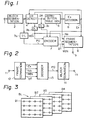
- Figure I shows the whole structure of the transmission side (recording side) of this invention.
- a digital television signal obtained by quantizing one sample into eight bits, for example, is given to an input terminal indicated at I.
- the digital television signal is supplied to a block segmentation circuit 2.
- the input digital television signal is converted by the block segmentation circuit 2 into a continuous signal representing each three dimensional block, which is a unit of encoding.
- the output signal of the circuit 2 is supplied to a delay circuit 3a and a dynamic range-detection circuit 4.
- the circuit 4 detects a dynamic range DR and a minimum value MIN for each block. Simultaneously, the detection circuit 4 obtains a number Nb of bits required for quantization using the detected DR and maximum distortion Ex.
- the dynamic range DR is given to a distribution table generating circuit 5.
- the circuit 5 sums up the distribution of all the dynamic ranges DRs every four frames.
- the summed distribution is supplied to a maximum-distortion-decision circuit 6.
- the circuit 6 decides the maximum distortion Ex (the circuit 6 is hereafter referred to as "Ex decision circuit 6").
- the maximum distortion is the maximum error value occurring at the time of decoding.
- the distribution of the dynamic ranges assumes a pattern showing a characteristic of picture information in four frame periods. For instance, in the case of a frequently moving picture or a picture having a fine picture pattern, the distribution of comparatively large dynamic ranges DRs is great, and the distribution of the dynamic ranges DRs does not concentrate on.a certain point. In contrast, in the case of a less moving picture or a picture having a large picture pattern, the distribution of small dynamic ranges is great, and the distribution concentrates on a certain point. To compare the former with the latter, the amount of information to be transmitted in the former is greater.
- the delay circuit 3a delays time and picture element data given at the dynamic range-detection circuit 4, the distribution table generating circuit 5 and the Ex decision circuit 6.
- Picture element data PD from the delay circuit 3a is quantized by an encoder 7 to be converted into an encoded code DT having the number of compressed bits.
- Picture element data PDI is produced by subtracting the minimum value MIN from the picture element data PD.
- the picture element data PDI is quantized.
- an encoded code DT is developed for indicating to which of plural level ranges that are formed by dividing the dynamic range of each block, the picture element data PDI belongs.
- the number of bits of the encoded code DT is determined by the dynamic range DR and the maximum distortion Ex.
- the encoded data DT is given to a frame segmentation circuit 8.
- the maximum distortion Ex is supplied to the circuit 8 as an additional code every four frames.
- the frame segmentation circuit 8 performs the processing for error correction and encoding for the encoded code DT and said additional codes, and adds a synchronisation signal.
- Transmission data is obtained at an output terminal 9 of the circuit 8, and the transmission data is sent out to the transmission line such as a digital channel.
- the encoded code DT has a variable bit number every block, the bit number of the block is necessarily determined from the necessary bit number Nb in the additional codes. As a result, despite the adoption of a variable length code, there is an advantage that no redundant code for showing the separation of data in the transmission data is needed.
- Figure 2 shows the structure on the reception (or reproduction) side.
- Reception data from an input terminal 11 is supplied to a frame separation circuit 12.
- the encoded code DT, and the additional codes Ex, Nb and MIN are separated by the circuit 12 and simultaneously error correction processing is performed.
- the encoded code DT and the additional codes are fed to a decoder 13.
- the decoder 13 performs the processing opposite to that of the encoder 7 on the transmission side. Namely, the data PDI (which was derived by subtracting the eight-bit minimum level from the original sample PD) is added to the minimum value MIN to give the picture element data PD.
- the output data PD of the decoder 13 is supplied to a block separation circuit 14. Contrary to the block segmentation circuit 2 on the transmission side, the block separation circuit 14 is a circuit for converting decoded data of the block order into the order similar to the television signal scanning. A decoded television signal is produced at an output terminal 15 of the block separation circuit 14.
- BL indicates one block consisting of two-dimensional areas BI, B2, B3 and B4, each of which belongs to each of four frames, and solid lines indicate lines in odd fields, while broken lines indicate lines in even fields.
- Figure 4 shows one example of the abovementioned block segmentation circuit 2.
- Frame memories 21, 22 and 23 are cascaded from the input terminal 1.
- Picture element data of the present frame F4 and picture element data of previous frames F3, F2 and Fl taken out of the frame memories 21, 22 and 23 respectively are given to a scanning conversion circuit 24.
- Respective picture element data of the corresponding two-dimensional areas BI, B2, B3 and B4 in four frames are sequentially obtained at an output terminal 25 of the scanning conversion circuit 24. That is, as shown in Figure 5, the corresponding areas BI, B2, B3 and B4 in the four continuous frames FI, F2, F3 and F4 are output in the order shown by the numerals.
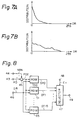
- Figure 6 shows a construction of one example of the dynamic range-detection circuit 4.
- Picture element data which requires the encoding of each block from the block segmentation circuit 2, is sequentially supplied to an input terminal 31.
- the picture element data from the input terminal 31 is fed to selectors 32 and 33.
- the selector 32 on one side selects and outputs data which is the larger of the picture element data of an input digital television signal and the output data of a latch 34.
- the selector 33 on the other side selects and outputs data which is the smaller of the picture element data of the input digital television signal and the output data of a latch 35.
- the output data of the selector 32 is supplied to a subtraction circuit 36 and taken into the latch 34.
- the output data of the selector 33 is given to the subtraction circuit 36 and a latch 38 and taken into the latch 35.
- a latch pulse is given from a control section 39 to the latches 34 and 35.
- Timing signals such as a sampling clock synchronised with the input digital television signal and a synchronisation signal are fed to the control section 39 from a terminal 40.
- the control section 39 supplies latch pulses to the latches 34 and 35 and the latches 37 and 38 at predetermined timings.
- the maximum level of the corresponding block appears at the output of the selector 32.
- the minimum level of the corresponding block is produced at the output of the selector 33.
- the initial setting for the latches 34 and 35 is performed again.
- the dynamic range DR of each block obtained by the subtraction of the maximum level MAX from the selector 32 and the minimum level MIN from the selector 33 is produced at the output of the subtraction circuit 36.
- These dynamic ranges DRs and minimum level MIN are latched into the latches 37 and 38 by the latch pulses from the control block 39.
- the dynamic range DR of each block is obtained at the output terminal 41 of the latch 37, while the minimum level MIN of each block is obtained at an output terminal 42 of the latch 38.
- a circuit for detecting the necessary bit number Nb determined by the DR and the maximum distortion Ex is provided, although it is omitted from Figure 6.
- a pattern of the distribution shown in Figure 7A indicates the case where the distribution of small DRs is greater.
- Such a pattern of the distribution as shown in Figure 7A is provided with respect to still pictures. pictures with less moving portions and large-patterned pictures. ln this case, since the bit number required for quantisation becomes small, the maximum distortion Ex is small.
- the pattern of the frequency distribution shown in Figure 7B shows the case where DRs are dispersed. Contrary to the abovementioned case, a pattern of the distribution such as shown in Figure 7B is produced with respect to pictures with many moving portions and pictures of fine picture pattern. In this latter case, because the bit number necessary for quantisation increases, the maximum distortion Ex becomes great.
- the bit number needed for quantisation is necessarily defined.
- the magnitude of the decoded value is supposed to take a fixed value as shown at the table given below.
- the level ranges are divided into four ranges of (0 - 8), (9 - 17), (18 - 26) and (27 - 35) and two-bit quantisation is performed by the four level ranges represented by [(00), (01), (10), (II)]. For instance, with a level (131) of a picture, the minimum value MIN is eliminated to convert the level into (31). Because the level (31) is included in the level range (27 - 35), it is quantised into an encoded code DT of (II).
- the minimum value (eight bits) MIN and the necessary bit number Nb (four bits) are sufficient for the additional codes for each block.
- any two of the minimum value (eight bits), the DR (eight bits) and the maximum value (eight bits) are needed as the additional codes.
- the data compression rate becomes low, but decoding distortion is greatly improved as compared with the previous system.
- the total bit number of encoded codes DTs in four frame periods is detected on the basis of data for showing the distribution of the abovementioned DR and the maximum distortion Ex.
- the total bit number in the four frame periods is calculated by the total bit number of the encoded codes DTs and that of the additional codes (maximum distortion Ex, the necessary bit number Nb of each block, minimum value MIN of each block).
- the value of the maximum distortion Ex is selected to be as small a value as possible.
- the reception side performs the decoding on the basis of the maximum distortion Ex and the necessary bit number Nb in reception data to output a decoded level.
- values [4, 13,22, 31] are used as decoded levels in the case of the necessary bit number Nb of two bits.
- a decoded level (31) is obtained, and (100) is added to the decoded level (31) to produce a decoded output of a level of (131).
- Figure 9 shows a specific example of the encoding and decoding of this one embodiment.
- an encoded code DT of (0) is output when the value of the data PDI lies in the range (0 - 8), and an encoded code DT of (I) is output with the value (9) of the data PDI.
- the DR can be recognised from reception data.
- the dynamic range DR is recognised as (9), and the necessary bit number corresponding to the DR is determined.
- the division number is determined from that necessary bit number, the two-division is done as shown in Figure 10.
- the dynamic range DR from an input terminal 46 of each block and the data PDI after the elimination of the minimum value are input in turn to the ROM 50 to the ROM 65.
- Quantisation is carried out with the bit number determined by a predetermined maximum distortion and the dynamic range DR so that encoded codes DTO to DT15 corresponding to the data PD are output from the ROMs 50 to 65, respectively
- the encoded codes DTO to DT15 are supplied to a selector 47.
- the maximum distortion Ex is applied to the selector 47 from a terminal 48, and an encoded code corresponding to the maximum distortion Ex is selected by the selector 47 to be taken out to an output terminal 49.
- the so-called linear quantisation technique or the technique to perform the quantisation so that the maximum distortion is made constant, has been employed.
- a non-linear quantisation technique may be adopted using a visual characteristic so that the deterioration is not noticeable in a large block even if the maximum distortion is large.
- T1, T2, T3 and T4 are threshold levels or values for determining the allocation bit numbers, respectively. Among those levels, there is a relationship of (T4 ⁇ T3 ⁇ T2 ⁇ T1).
- DR (T4-I)
- a middle level LO is employed as a decoded level.
- the quantisation width becomes ⁇ 0.
- the allocation bit number is 0.
- non-linear quantisation is carried out so that the quantisation width ⁇ i ( ⁇ 0 ⁇ ⁇ 1 ⁇ ⁇ 2 ⁇ ⁇ 3 ⁇ A4) increases with DR.
- the maximum distortion is made small in a block with a small DR, which gives noticeable encoding distortion, whereas the maximum distortion is made large in a block having a large DR. This contributes to the enhancement of compression rate.
- DR (T2-1).
- a detected DR is divided into four level ranges as shown at C of Figure II, and two bits (00), (01). (10) and (II) are allotted to the respective level ranges.
- the middle levels of those ranges become the decoded levels L0, L1, L2 and L3. Therefore, the level range to which the data PDI belongs, is examined using the quantisation width ⁇ 2.
- the allocation bit number becomes two.
- a detected DR is divided into eight level ranges, and three bits (000) (001) ... (III) are allotted to the respective ranges.
- the middle levels of those ranges become the decoded levels L0, L1, ... L7. For this reason, the quantisation width is made to A3.
- the allocation bit number is three.
- DR 255
- a detected DR is divided into 16 level ranges as shown at E of Figure II, and four bits (0000), (0001.... (IIII) are allotted to the respective ranges.
- the middle levels of those ranges are made to the decoded levels L0, Ll, ... L15.
- the quantisation width consequently becomes ⁇ 4.
- the allocation bit number is four bits.
- the threshold values Tl to T4 for example, the following eleven sets, which are differentiated .by the parameter codes Pi, are prepared at the maximum transmission rate (2 bits/picture element).
- the threshold value set designated by the parameter code PI can provide the minimum quantisation distortion.
- the distribution table generation circuit 5 the distribution of the dynamic ranges DRs of all blocks in one frame is obtained.
- ADRC adaptive dynamic range coding
- Said information amount is compared with an already known data threshold value so that a threshold value set, which provides as little distortion as possible, can be determined within the range that said amount does not exceed the data threshold value.
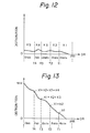
- Figure 12 shows an example of the distribution.
- the abscissa indicates the dynamic ranges DRs ranging from 0 to 255, whereas the ordinate indicates the distribution.
- xl, x2, x3, x4 and x5 represent block numbers included in five ranges of the DRs, which have been divided by the threshold values TI to T4. Since 0 bit is allotted to the blocks having DRs equal to or less (T4-1), the block number x5 does not contribute to the generated information amount. As a result, this amount can be obtained by 4xl + 3x2 + 2x3 + x4.
- the generated information is compared with the data threshold value. When the former exceeds the latter, a set having a larger threshold value is applied, and the generated information amount is calculated similarly.
- the processes for obtaining the sum of the distribution within each range of each pre-established threshold value set, multiplying the allocation bit number by said sum, and adding the multiplied value are needed. However, if these processes are carried out each time the threshold value sets are changed, it takes time to finally obtain an optimum threshold value set.
- the distribution shown in Figure 12 is converted into the integrating type one shown in Figure 13 so that the generated information amount corresponding to different threshold value sets can be calculated at higher speed so as to reduce the finalising time taken until the optimum threshold value set is obtained.
- an integrating type distribution graph is obtained by sequentially integrating the generation distribution of smaller DRs starting at the distribution of the maximum DR.
- the integrating distribution up to the threshold value TI becomes xl.
- (xl + x2), (xl + x2 + x3) and (xl + x2 + x3 + x4) are the integrating distribution up to the threshold values T2, T3 and T4, respectively.
- FIG 14 is a flow chart for describing the abovementioned buffering operation.
- the dynamic ranges DRs of all blocks in one picture. for example one frame are detected (step (I)).
- the distribution table (refer to Figure 12) of the DRs in one frame is then made (step (2)).
- This distribution table is converted into the integrating type one (refer to Figure 13) (step (3)).
- the generated information for the threshold value sets is calculated (step (4)). In this case, the calculation at step (4) starts at the threshold value set, which provides the minimum quantisation distortion (the threshold value set assumed by the parameter code PI).
- the generated information amount obtained is compared with an objective value (data threshold value) (step (5)).
- the objective value is the maximum value of the transmission data (for example, two bits/picture elements). This comparison result is judged at the step (6).
- the ADRC is done using the threshold value set which provides the minimum quantisation distortion (step (7)). If said information amount exceeds the objective value, the threshold value set is updated (step (8)), and the steps (4), (5) and (6) are repeated with respect to a new threshold value set, which provides larger quantisation distortion.
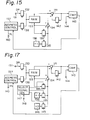
- Figure 15 shows an example of a circuit for the above-described buffering operation. This circuit is employed in place of the distribution table generating circuit 5 and the Ex decision circuit 6 shown in Figure I.
- a dynamic range DR is supplied to an input terminal 131.
- the DR is given to a RAM (random access memory) 133 as an address signal through a register 132 having an output control function.
- the RAM 133 has addresses (0 to 255), and in its initial state, all the memory contents of the RAM are cleared.
- Data read out from the RAM 133 is sent to an adder 134.
- the output data of the adder 134 is supplied to the RAM 133 as data input.
- Dynamic ranges DRs of each block are given to the RAM 133 via the register 132 after the initialisation has been completed.
- the output data of the adder 134 is written in the same address. Every time the address corresponding to the DR is accessed, data at that address is incremented, since the output of a (+1) generator 136 is supplied to the adder 134 through a register 135. Therefore, at the time the supply of the DRs of all blocks in one frame has been completed, the DR distribution table is stored at the RAM 133.
- registers 138 and 139 are brought into output-enabling states, the register 135 is brought into an output-disabling state, and the integrating type distribution table is made.
- An address signal from an address controller 137 is given to the RAM 133 through the register 138. This address signal is used for the decrement of (-I) from 255.
- Data read out of the RAM 133 is added to data previously read and stored in the register 139 at the adder 134. Since the output data of the adder 134 is written in the same address as the read address in the RAM 133, the integrating type distribution table is stored in the RAM 133 at the time the address has been decremented to 0.
- the threshold values TI, T2, T3 and T4 which provide the minimum distortion, are sequentially supplied to the RAM 133 from the address controller 137.
- the threshold value TI the distribution xl is read from the RAM 133 and given to an adder 141.
- the output signal 141 is fed back thereto through a register 142 and supplied to a comparator 143.
- the comparator 143 compares a data threshold value (objective value) from a terminal 144 with the generated information value from the adder 141.
- the threshold value T2 following the threshold value TI is given to the RAM 133.
- (xl + x2) is read out from the RAM 133 and added to xl stored in the register 142 at the adder 141.
- the addition output is fed to the register 142.
- (xl + x2 + x3) is then read out of the RAM 133 and added to (2xl + x2) stored in the register 142 at the adder 141.
- the threshold value T4 is given to the RAM 133, the output read out of the RAM 133 and the output of the register 142 are added at the adder 141.
- the output of the adder 141 is 4xl + 3x2 + 2x3 + 1x4.
- This output of the adder 141 is the generated information amount corresponding to the threshold values TI to T4.
- the comparator 143 generates a "0" comparison output signal when said amount exceeds the data threshold value, whereas the comparator 143 produces a "1" comparison output signal when said amount does not exceed the data threshold value. These comparison output signals are given to the address controller 137. The controller stops updating the threshold data value in response to the "1" comparison output, and produces the parameter code Pi indicative of the threshold value at that time to an output terminal 140.
- the process for converting the abovedescribed distribution table of the DRs into the integrating type one and the process for determining the optimum threshold value can be executed in the vertical blanking period. Further a reduction of the processing time can be achieved by the adoption of a structure for allowing the capacity of the RAM 133 to quadruple and the integrating distribution to be output in parallel.
- Figure 16 shows a structure of an example of the address controller 137.
- an address counter 151 generates an address for decrementing (-1) from 255 at the time of making the integrating type distribution table.
- the address from the counter 151 is supplied to the RAM 133 through a register 152 having an output control function.
- Eleven sets of threshold values are stored in four ROMs 153 156 such that the threshold values corresponding to TI, T2, T3 and T4 are stored in ROMs 153,154,155 and 156 respectively.
- a four-bit parameter code Pi generated at an address counter 157 is given to the ROMs 153 to 156 as an address.
- the counter 157 is incremented by a pulse signal from a pulse generator 158.
- the comparison output signal of the comparator 143 is fed to the pulse generator 158, and a pulse signal having a predetermined period is given by the pulse generator 158 to the address counter 157 while said comparison output signal is "0". Consequently, threshold values are sequentially read out of the ROMs 153 to 156 until the generated information amount becomes equal to or smaller than the data threshold value.
- the threshold values read from the ROMs 153 to 156 are supplied to registers 159, 160, 161 and 162, each of which has an output control function, respectively.
- the register 159, 160, 161 and 162 sequentially output threshold values in that order starting at the register 159.
- the parameter code Pi generated at the address counter 157 is taken out from an output terminal 164 via a gate circuit 163.
- the threshold values TI to T4 read from the ROMs 153 to 156 are taken out of output terminals 169,170,171 and 172 through gate circuits 165,166,167 and 168.
- the gate circuits 163 and 165 to 168 are brought into "ON" states in response to the "I" comparison output signal.
- the optimum threshold value set and the parameter code Pi for specifying this threshold value set are produced at the output terminals 164 and 169 to 172, respectively.
- the threshold value and code Pi are employed for ADRC.
- the example of the above mentioned buffering can be applied to ADRC for three-dimensional blocks. If the three-dimensional blocks are composed of two two-dimensional areas belonging to two frames, for instance, the number of picture elements in one block becomes double.
- ADRC for three-dimensions blocks the presence or absence of changes between the two-dimensional areas is detected with a view to enhancing the compression rate. In the presence of change, the picture element data in the two two-dimensional areas, or, in other words, all the picture element data in a block is encoded. On the other hand, in the absence of change the picture element data in one two-dimensional area is encoded. As a result, the ratio of the generated information amount at a still part of the picture and a moving part becomes (1:2).
- FIG 17. Another structure of the buffering circuit when the invention is applied to the above-described three-dimensional ADRC is illustrated in Figure 17.
- a register 145 having an output control function, a (+2) generator 146 and a selection signal generator 147 are provided.
- a flag for indicating the presence or absence of change is given via a terminal 148 to the generator 147.
- the registers 135, 139 and 145 are controlled by a selection signal from the selection signal generator 147.
- a dynamic range sample DR is fed via an input terminal 131 to a register 132 having an output control function.
- the output of register 145 is enabled by a movement flag of each block to give (+2) to an adder 134 at a moving part of the picture and, at the still part, the output of register 135 is enabled to give to the adder 134.
- the distribution table of the DRs is formed in the RAM 133.
- one block of data may be taken out by a circuit composed of the combination of a frame memory, a line delay circuit and a sample delay circuit.
- this invention permits the transmission rate to be constant. However, slight adjustment for the amount of data to be transmitted may be done using a buffer memory of small capacity.
- the amount of data to be transmitted can be reduced as compared with that of the original data, and the transmission band can be narrowed. Also, the invention provides the advantage that the degradation of picture quality hardly occurs, because original picture element data can be almost perfectly recovered from reception data at the stationary portion having narrow width of a picture element data change. Further, since the dynamic range is determined in one-to-one correspondence with each block, the response at a transient portion such as an edge portion having great change width becomes satisfactory.
- the invention enables the effective use of the transmission capacity of a transmission line, since the transmission rate of encoded output is brought to be constant by performing the encoding adapative to the amount of generated information such as moving. Also, in this invention, since the quantisation bit number is selected adaptive to the dynamic range in a block, a reproduced picture of excellent quality with uniform distortion can be produced. In addition, the invention allows variable length encoding without any codes for data separation thereby performing further compression.
Landscapes
- Engineering & Computer Science (AREA)
- Multimedia (AREA)
- Signal Processing (AREA)
- Compression Or Coding Systems Of Tv Signals (AREA)
- Soft Magnetic Materials (AREA)
- Compression, Expansion, Code Conversion, And Decoders (AREA)
- Analogue/Digital Conversion (AREA)
- Optical Transform (AREA)
- Transmission And Conversion Of Sensor Element Output (AREA)
Priority Applications (1)
| Application Number | Priority Date | Filing Date | Title |
|---|---|---|---|
| AT86309274T ATE75358T1 (de) | 1985-11-29 | 1986-11-27 | Hochwirksame kodiereinrichtung. |
Applications Claiming Priority (2)
| Application Number | Priority Date | Filing Date | Title |
|---|---|---|---|
| JP268817/85 | 1985-11-29 | ||
| JP26881785A JP2670259B2 (ja) | 1985-11-29 | 1985-11-29 | 高能率符号化装置 |
Publications (3)
| Publication Number | Publication Date |
|---|---|
| EP0225181A2 true EP0225181A2 (de) | 1987-06-10 |
| EP0225181A3 EP0225181A3 (en) | 1988-06-01 |
| EP0225181B1 EP0225181B1 (de) | 1992-04-22 |
Family
ID=17463666
Family Applications (1)
| Application Number | Title | Priority Date | Filing Date |
|---|---|---|---|
| EP19860309274 Expired - Lifetime EP0225181B1 (de) | 1985-11-29 | 1986-11-27 | Hochwirksame Kodiereinrichtung |
Country Status (7)
| Country | Link |
|---|---|
| US (1) | US4722003A (de) |
| EP (1) | EP0225181B1 (de) |
| JP (1) | JP2670259B2 (de) |
| AT (1) | ATE75358T1 (de) |
| AU (1) | AU591947B2 (de) |
| CA (1) | CA1278096C (de) |
| DE (1) | DE3685000D1 (de) |
Cited By (7)
| Publication number | Priority date | Publication date | Assignee | Title |
|---|---|---|---|---|
| EP0222592A3 (en) * | 1985-11-05 | 1988-08-31 | Sony Corporation | High efficiency technique for coding a digital video signal |
| EP0373924A1 (de) * | 1988-12-16 | 1990-06-20 | Sony Corporation | Kodiereinrichtung |
| EP0296608A3 (en) * | 1987-06-25 | 1990-12-12 | Nec Corporation | Encoding of a picture signal in consideration of contrast in each picture and decoding corresponding to the encoding |
| EP0387401A3 (de) * | 1989-03-11 | 1991-06-26 | ANT Nachrichtentechnik GmbH | Verfahren zur Gewinnung eines Änderungskriteriums für eine Bildsequenz sowie eine Anwendung des Verfahrens |
| EP0398741A3 (de) * | 1989-05-19 | 1991-08-28 | Canon Kabushiki Kaisha | System zum Übertragen von Bildinformation |
| GB2249238A (en) * | 1990-08-23 | 1992-04-29 | Fuji Xerox Co Ltd | Image encoding apparatus |
| AU693388B2 (en) * | 1995-11-22 | 1998-06-25 | Medtronic, Inc. | System and method for compressing digitized signals in implantable and battery powered devices |
Families Citing this family (97)
| Publication number | Priority date | Publication date | Assignee | Title |
|---|---|---|---|---|
| US5142272A (en) * | 1987-05-21 | 1992-08-25 | Sony Corporation | Method and apparatus for processing display color signal |
| JP2508439B2 (ja) * | 1987-05-29 | 1996-06-19 | ソニー株式会社 | 高能率符号化装置 |
| JP2789584B2 (ja) * | 1987-10-23 | 1998-08-20 | ソニー株式会社 | 高能率符号化装置 |
| US5070402A (en) * | 1987-11-27 | 1991-12-03 | Canon Kabushiki Kaisha | Encoding image information transmission apparatus |
| US4953019A (en) * | 1987-11-27 | 1990-08-28 | Canon Kabushiki Kaisha | Image signal encoding apparatus |
| JP2827221B2 (ja) * | 1988-07-23 | 1998-11-25 | ソニー株式会社 | 高能率符号化装置及び高能率符号化方法 |
| WO1990002465A2 (en) * | 1988-08-23 | 1990-03-08 | Waldemar Kehler | Hierarchically range adaptive coding method for signals, especially suitable for picture analysis and codings |
| JPH0271690A (ja) * | 1988-09-07 | 1990-03-12 | Canon Inc | 画像伝送システム |
| JPH02119486A (ja) * | 1988-10-28 | 1990-05-07 | Nec Corp | 動画像信号の符号化制御方法および符号化制御器 |
| US5051840A (en) * | 1988-12-14 | 1991-09-24 | Fuji Photo Film Co., Ltd. | Device for coding a picture signal by compression |
| US4955037A (en) * | 1989-01-19 | 1990-09-04 | Bell Communications Research Inc. | Apparatus and methods for recovering alignment from a non-ideally encoded multi-bit digital signal |
| AU612543B2 (en) * | 1989-05-11 | 1991-07-11 | Panasonic Corporation | Moving image signal encoding apparatus and decoding apparatus |
| JP2833005B2 (ja) * | 1989-05-19 | 1998-12-09 | ソニー株式会社 | フレーム分解回路及び方法 |
| JP2830111B2 (ja) * | 1989-07-21 | 1998-12-02 | ソニー株式会社 | 高能率符号化装置 |
| JP2906671B2 (ja) * | 1990-12-28 | 1999-06-21 | ソニー株式会社 | ディジタルビデオ信号の高能率符号化装置およびその方法 |
| TW256010B (de) * | 1991-04-18 | 1995-09-01 | Ampex | |
| JPH0556418A (ja) * | 1991-08-28 | 1993-03-05 | Sharp Corp | 画像符号化装置 |
| US5850261A (en) * | 1992-10-15 | 1998-12-15 | Sony Corporation | Efficient variable length encoder and decoder |
| JPH06141304A (ja) | 1992-10-28 | 1994-05-20 | Sony Corp | 演算回路 |
| JPH07115646A (ja) * | 1993-10-20 | 1995-05-02 | Sony Corp | 画像処理装置 |
| US6212663B1 (en) | 1997-10-23 | 2001-04-03 | Sony Corporation | Apparatus and method for recovery of quantization codes in a lossy transmission environment |
| CN1337031A (zh) | 1997-10-23 | 2002-02-20 | 索尼电子有限公司 | 用于有损耗传输环境中量化码恢复的设备和方法 |
| CN1174631C (zh) * | 1997-10-23 | 2004-11-03 | 索尼电子有限公司 | 部分缓存发送的数据以便提供增强的差错恢复 |
| US6581170B1 (en) | 1997-10-23 | 2003-06-17 | Sony Corporation | Source coding to provide for robust error recovery during transmission losses |
| US6282684B1 (en) | 1997-10-23 | 2001-08-28 | Sony Corporation | Apparatus and method for recovery of data in a lossy transmission environment |
| US6621936B1 (en) | 1999-02-12 | 2003-09-16 | Sony Corporation | Method and apparatus for spatial class reduction |
| US6307560B1 (en) | 1999-02-12 | 2001-10-23 | Sony Corporation | Classified adaptive spatio-temporal format conversion method and apparatus |
| US7010737B2 (en) * | 1999-02-12 | 2006-03-07 | Sony Corporation | Method and apparatus for error data recovery |
| US6363118B1 (en) | 1999-02-12 | 2002-03-26 | Sony Corporation | Apparatus and method for the recovery of compression constants in the encoded domain |
| US6154761A (en) * | 1999-02-12 | 2000-11-28 | Sony Corporation | Classified adaptive multiple processing system |
| US6178266B1 (en) | 1999-02-12 | 2001-01-23 | Sony Corporation | Method and apparatus for the recovery of compression constants in the encoded domain |
| US6192161B1 (en) | 1999-02-12 | 2001-02-20 | Sony Corporation | Method and apparatus for adaptive filter tap selection according to a class |
| US6591398B1 (en) | 1999-02-12 | 2003-07-08 | Sony Corporation | Multiple processing system |
| US6535148B1 (en) | 1999-02-12 | 2003-03-18 | Sony Corporation | Method and apparatus for truncated decoding |
| US6151416A (en) * | 1999-02-12 | 2000-11-21 | Sony Corporation | Method and apparatus for adaptive class tap selection according to multiple classification |
| US6519369B1 (en) | 1999-02-12 | 2003-02-11 | Sony Corporation | Method and apparatus for filter tap expansion |
| US6307979B1 (en) | 1999-02-12 | 2001-10-23 | Sony Corporation | Classified adaptive error recovery method and apparatus |
| US6170074B1 (en) | 1999-02-12 | 2001-01-02 | Sony Corporation | Source coding to provide for robust error recovery |
| US7565546B2 (en) | 1999-03-30 | 2009-07-21 | Sony Corporation | System, method and apparatus for secure digital content transmission |
| US7730300B2 (en) * | 1999-03-30 | 2010-06-01 | Sony Corporation | Method and apparatus for protecting the transfer of data |
| US6697489B1 (en) | 1999-03-30 | 2004-02-24 | Sony Corporation | Method and apparatus for securing control words |
| US6493842B1 (en) | 1999-06-29 | 2002-12-10 | Sony Corporation | Time-varying randomization for data synchronization and implicit information transmission |
| US6389562B1 (en) | 1999-06-29 | 2002-05-14 | Sony Corporation | Source code shuffling to provide for robust error recovery |
| US6549672B1 (en) | 1999-06-29 | 2003-04-15 | Sony Corporation | Method and apparatus for recovery of encoded data using central value |
| US6473876B1 (en) | 1999-06-29 | 2002-10-29 | Sony Corporation | Method and apparatus for encoding of bitstreams using rotation |
| US6351494B1 (en) | 1999-09-24 | 2002-02-26 | Sony Corporation | Classified adaptive error recovery method and apparatus |
| US6522785B1 (en) | 1999-09-24 | 2003-02-18 | Sony Corporation | Classified adaptive error recovery method and apparatus |
| US6539517B1 (en) | 1999-11-09 | 2003-03-25 | Sony Corporation | Data transformation for explicit transmission of control information |
| US7039614B1 (en) | 1999-11-09 | 2006-05-02 | Sony Corporation | Method for simulcrypting scrambled data to a plurality of conditional access devices |
| US6754371B1 (en) | 1999-12-07 | 2004-06-22 | Sony Corporation | Method and apparatus for past and future motion classification |
| US7225164B1 (en) | 2000-02-15 | 2007-05-29 | Sony Corporation | Method and apparatus for implementing revocation in broadcast networks |
| US20030206631A1 (en) * | 2000-06-22 | 2003-11-06 | Candelore Brant L. | Method and apparatus for scrambling program data for furture viewing |
| US20040205812A1 (en) * | 2000-06-22 | 2004-10-14 | Candelore Brant L. | Method and apparatus for routing program data in a program viewing unit |
| US8374237B2 (en) | 2001-03-02 | 2013-02-12 | Dolby Laboratories Licensing Corporation | High precision encoding and decoding of video images |
| US7895616B2 (en) * | 2001-06-06 | 2011-02-22 | Sony Corporation | Reconstitution of program streams split across multiple packet identifiers |
| US7747853B2 (en) | 2001-06-06 | 2010-06-29 | Sony Corporation | IP delivery of secure digital content |
| US7127619B2 (en) * | 2001-06-06 | 2006-10-24 | Sony Corporation | Decoding and decryption of partially encrypted information |
| US7350082B2 (en) * | 2001-06-06 | 2008-03-25 | Sony Corporation | Upgrading of encryption |
| US7765567B2 (en) * | 2002-01-02 | 2010-07-27 | Sony Corporation | Content replacement by PID mapping |
| US7823174B2 (en) * | 2002-01-02 | 2010-10-26 | Sony Corporation | Macro-block based content replacement by PID mapping |
| US7376233B2 (en) * | 2002-01-02 | 2008-05-20 | Sony Corporation | Video slice and active region based multiple partial encryption |
| US7155012B2 (en) * | 2002-01-02 | 2006-12-26 | Sony Corporation | Slice mask and moat pattern partial encryption |
| US7233669B2 (en) * | 2002-01-02 | 2007-06-19 | Sony Corporation | Selective encryption to enable multiple decryption keys |
| US7218738B2 (en) * | 2002-01-02 | 2007-05-15 | Sony Corporation | Encryption and content control in a digital broadcast system |
| US7302059B2 (en) * | 2002-01-02 | 2007-11-27 | Sony Corporation | Star pattern partial encryption |
| US7242773B2 (en) * | 2002-09-09 | 2007-07-10 | Sony Corporation | Multiple partial encryption using retuning |
| US7292691B2 (en) | 2002-01-02 | 2007-11-06 | Sony Corporation | Progressive video refresh slice detection |
| US7039938B2 (en) * | 2002-01-02 | 2006-05-02 | Sony Corporation | Selective encryption for video on demand |
| US7215770B2 (en) * | 2002-01-02 | 2007-05-08 | Sony Corporation | System and method for partially encrypted multimedia stream |
| US20090180025A1 (en) * | 2002-05-28 | 2009-07-16 | Sony Corporation | Method and apparatus for overlaying graphics on video |
| US7530084B2 (en) * | 2002-05-28 | 2009-05-05 | Sony Corporation | Method and apparatus for synchronizing dynamic graphics |
| US8818896B2 (en) * | 2002-09-09 | 2014-08-26 | Sony Corporation | Selective encryption with coverage encryption |
| US8572408B2 (en) | 2002-11-05 | 2013-10-29 | Sony Corporation | Digital rights management of a digital device |
| US7724907B2 (en) | 2002-11-05 | 2010-05-25 | Sony Corporation | Mechanism for protecting the transfer of digital content |
| US8667525B2 (en) * | 2002-12-13 | 2014-03-04 | Sony Corporation | Targeted advertisement selection from a digital stream |
| US8645988B2 (en) * | 2002-12-13 | 2014-02-04 | Sony Corporation | Content personalization for digital content |
| US20040165586A1 (en) * | 2003-02-24 | 2004-08-26 | Read Christopher Jensen | PID filters based network routing |
| US7409702B2 (en) * | 2003-03-20 | 2008-08-05 | Sony Corporation | Auxiliary program association table |
| US7292692B2 (en) | 2003-03-25 | 2007-11-06 | Sony Corporation | Content scrambling with minimal impact on legacy devices |
| US20050036067A1 (en) * | 2003-08-05 | 2005-02-17 | Ryal Kim Annon | Variable perspective view of video images |
| US7286667B1 (en) | 2003-09-15 | 2007-10-23 | Sony Corporation | Decryption system |
| US20050066357A1 (en) * | 2003-09-22 | 2005-03-24 | Ryal Kim Annon | Modifying content rating |
| US20050097597A1 (en) * | 2003-10-31 | 2005-05-05 | Pedlow Leo M.Jr. | Hybrid storage of video on demand content |
| US7620180B2 (en) * | 2003-11-03 | 2009-11-17 | Sony Corporation | Preparation of content for multiple conditional access methods in video on demand |
| US7346163B2 (en) * | 2003-10-31 | 2008-03-18 | Sony Corporation | Dynamic composition of pre-encrypted video on demand content |
| US20050097596A1 (en) * | 2003-10-31 | 2005-05-05 | Pedlow Leo M.Jr. | Re-encrypted delivery of video-on-demand content |
| US7263187B2 (en) * | 2003-10-31 | 2007-08-28 | Sony Corporation | Batch mode session-based encryption of video on demand content |
| US7853980B2 (en) * | 2003-10-31 | 2010-12-14 | Sony Corporation | Bi-directional indices for trick mode video-on-demand |
| US7343013B2 (en) * | 2003-12-16 | 2008-03-11 | Sony Corporation | Composite session-based encryption of video on demand content |
| US20050102702A1 (en) * | 2003-11-12 | 2005-05-12 | Candelore Brant L. | Cablecard with content manipulation |
| US20050169473A1 (en) * | 2004-02-03 | 2005-08-04 | Candelore Brant L. | Multiple selective encryption with DRM |
| US7895617B2 (en) * | 2004-12-15 | 2011-02-22 | Sony Corporation | Content substitution editor |
| US8041190B2 (en) | 2004-12-15 | 2011-10-18 | Sony Corporation | System and method for the creation, synchronization and delivery of alternate content |
| US8185921B2 (en) | 2006-02-28 | 2012-05-22 | Sony Corporation | Parental control of displayed content using closed captioning |
| US7555464B2 (en) * | 2006-03-01 | 2009-06-30 | Sony Corporation | Multiple DRM management |
| US9172960B1 (en) * | 2010-09-23 | 2015-10-27 | Qualcomm Technologies, Inc. | Quantization based on statistics and threshold of luminanceand chrominance |
| US20230267309A1 (en) * | 2020-06-18 | 2023-08-24 | Interdigital Vc Holdings France, Sas | Systems and methods for encoding/decoding a deep neural network |
Citations (1)
| Publication number | Priority date | Publication date | Assignee | Title |
|---|---|---|---|---|
| US4710811A (en) | 1984-12-21 | 1987-12-01 | Sony Corporation | Highly efficient coding apparatus for a digital video signal |
Family Cites Families (10)
| Publication number | Priority date | Publication date | Assignee | Title |
|---|---|---|---|---|
| JPS54132116A (en) * | 1978-04-06 | 1979-10-13 | Ricoh Co Ltd | Picture signal process method |
| JPS5683176A (en) * | 1979-12-07 | 1981-07-07 | Fuji Electric Co Ltd | Compression and restoration system for video data |
| JPS57148430A (en) * | 1981-03-10 | 1982-09-13 | Victor Co Of Japan Ltd | Compression system and compression and expansion system for video composite signal |
| JPS59153378A (ja) * | 1983-02-21 | 1984-09-01 | Sony Corp | 画像信号形成方法 |
| JPS59200592A (ja) * | 1983-04-27 | 1984-11-13 | Fuji Photo Film Co Ltd | カラ−画像の適応形圧縮方式 |
| JPS6054581A (ja) * | 1983-09-06 | 1985-03-29 | Nec Corp | 差分符号化装置 |
| JPS60180388A (ja) * | 1984-02-28 | 1985-09-14 | Kokusai Denshin Denwa Co Ltd <Kdd> | 符号化された画像信号の再量子化方法 |
| JPS61114676A (ja) * | 1984-11-09 | 1986-06-02 | Nec Corp | ブロツク符号化装置 |
| JPS61118085A (ja) * | 1984-11-14 | 1986-06-05 | Nec Corp | 画像信号の符号化方式およびその装置 |
| JP3271018B2 (ja) * | 1992-07-09 | 2002-04-02 | 大日本印刷株式会社 | 液晶光学素子の製造方法 |
-
1985
- 1985-11-29 JP JP26881785A patent/JP2670259B2/ja not_active Expired - Lifetime
-
1986
- 1986-11-19 US US06/932,274 patent/US4722003A/en not_active Expired - Lifetime
- 1986-11-19 CA CA 523298 patent/CA1278096C/en not_active Expired - Lifetime
- 1986-11-26 AU AU65715/86A patent/AU591947B2/en not_active Expired
- 1986-11-27 EP EP19860309274 patent/EP0225181B1/de not_active Expired - Lifetime
- 1986-11-27 AT AT86309274T patent/ATE75358T1/de not_active IP Right Cessation
- 1986-11-27 DE DE8686309274T patent/DE3685000D1/de not_active Expired - Lifetime
Patent Citations (1)
| Publication number | Priority date | Publication date | Assignee | Title |
|---|---|---|---|---|
| US4710811A (en) | 1984-12-21 | 1987-12-01 | Sony Corporation | Highly efficient coding apparatus for a digital video signal |
Cited By (10)
| Publication number | Priority date | Publication date | Assignee | Title |
|---|---|---|---|---|
| EP0222592A3 (en) * | 1985-11-05 | 1988-08-31 | Sony Corporation | High efficiency technique for coding a digital video signal |
| EP0296608A3 (en) * | 1987-06-25 | 1990-12-12 | Nec Corporation | Encoding of a picture signal in consideration of contrast in each picture and decoding corresponding to the encoding |
| EP0373924A1 (de) * | 1988-12-16 | 1990-06-20 | Sony Corporation | Kodiereinrichtung |
| US5023710A (en) * | 1988-12-16 | 1991-06-11 | Sony Corporation | Highly efficient coding apparatus |
| EP0387401A3 (de) * | 1989-03-11 | 1991-06-26 | ANT Nachrichtentechnik GmbH | Verfahren zur Gewinnung eines Änderungskriteriums für eine Bildsequenz sowie eine Anwendung des Verfahrens |
| EP0398741A3 (de) * | 1989-05-19 | 1991-08-28 | Canon Kabushiki Kaisha | System zum Übertragen von Bildinformation |
| US5448298A (en) * | 1989-05-19 | 1995-09-05 | Canon Kabushiki Kaisha | Image information transmitting system |
| GB2249238A (en) * | 1990-08-23 | 1992-04-29 | Fuji Xerox Co Ltd | Image encoding apparatus |
| GB2249238B (en) * | 1990-08-23 | 1995-02-01 | Fuji Xerox Co Ltd | Image encoding apparatus |
| AU693388B2 (en) * | 1995-11-22 | 1998-06-25 | Medtronic, Inc. | System and method for compressing digitized signals in implantable and battery powered devices |
Also Published As
| Publication number | Publication date |
|---|---|
| AU591947B2 (en) | 1989-12-21 |
| AU6571586A (en) | 1987-06-04 |
| JP2670259B2 (ja) | 1997-10-29 |
| ATE75358T1 (de) | 1992-05-15 |
| EP0225181A3 (en) | 1988-06-01 |
| DE3685000D1 (de) | 1992-05-27 |
| EP0225181B1 (de) | 1992-04-22 |
| US4722003A (en) | 1988-01-26 |
| CA1278096C (en) | 1990-12-18 |
| JPS62128621A (ja) | 1987-06-10 |
Similar Documents
| Publication | Publication Date | Title |
|---|---|---|
| EP0225181A2 (de) | Hochwirksame Kodiereinrichtung | |
| US4802005A (en) | High efficiency encoding system | |
| EP0473384B1 (de) | Kodierungsgerät für digitale Bildsignale | |
| EP0282135B1 (de) | Fernsehsystem, in dem digitalisierte transformationskodierte Bildsignale von einer Kodierstation zu einer Dekodierstation übertragen werden | |
| US4437119A (en) | Inter-frame adaptive prediction system for television signals | |
| EP0222592B1 (de) | Zweckmässige Technik zum Kodieren eines digitalen Videosignals | |
| US4200886A (en) | Method for transmitting video signals with the aid of DPC modulation and controlled quantizer | |
| EP0185533A2 (de) | Hochleistungsfähige Technik zur Kodierung eines digitalen Videosignals | |
| EP0385654A2 (de) | Kodiergerät von hoher Wirksamkeit | |
| US5448298A (en) | Image information transmitting system | |
| EP0361761A2 (de) | Digitaler Videokoder | |
| US4910594A (en) | Method and apparatus for adaptively compressing a video signal in accordance with the valves of individual pixels | |
| US5068726A (en) | Coding apparatus that temporally interpolates block data and selects transmission mode | |
| EP0364261A2 (de) | Kodiergerät mit hoher Wirksamkeit | |
| US6046774A (en) | Device and method for variable length coding of video signals depending on the characteristics | |
| US5023715A (en) | Method of and apparatus for transmitting image information | |
| US4320416A (en) | Technique for optimally encoding digitally encoded video signals | |
| EP0417914B1 (de) | Dekodierungs- und Kodierungsgerät für komprimierte digitale Videodaten | |
| US5047854A (en) | Image information transmission system transmitting maximum and minimum value data | |
| JP2604712B2 (ja) | テレビジヨン信号の高能率符号化/復号装置 | |
| US5151791A (en) | Efficient encoding of picture signal | |
| JP2518215B2 (ja) | 高能率符号化装置 | |
| JPS62123834A (ja) | 符号化伝送装置 | |
| JP2778629B2 (ja) | 高能率符号化装置 | |
| JP2684720B2 (ja) | 画像信号の高能率符号化装置 |
Legal Events
| Date | Code | Title | Description |
|---|---|---|---|
| PUAI | Public reference made under article 153(3) epc to a published international application that has entered the european phase |
Free format text: ORIGINAL CODE: 0009012 |
|
| 17P | Request for examination filed |
Effective date: 19861203 |
|
| AK | Designated contracting states |
Kind code of ref document: A2 Designated state(s): AT DE FR GB NL |
|
| PUAL | Search report despatched |
Free format text: ORIGINAL CODE: 0009013 |
|
| AK | Designated contracting states |
Kind code of ref document: A3 Designated state(s): AT DE FR GB NL |
|
| 17Q | First examination report despatched |
Effective date: 19900822 |
|
| GRAA | (expected) grant |
Free format text: ORIGINAL CODE: 0009210 |
|
| AK | Designated contracting states |
Kind code of ref document: B1 Designated state(s): AT DE FR GB NL |
|
| REF | Corresponds to: |
Ref document number: 75358 Country of ref document: AT Date of ref document: 19920515 Kind code of ref document: T |
|
| REF | Corresponds to: |
Ref document number: 3685000 Country of ref document: DE Date of ref document: 19920527 |
|
| ET | Fr: translation filed | ||
| PLBE | No opposition filed within time limit |
Free format text: ORIGINAL CODE: 0009261 |
|
| STAA | Information on the status of an ep patent application or granted ep patent |
Free format text: STATUS: NO OPPOSITION FILED WITHIN TIME LIMIT |
|
| 26N | No opposition filed | ||
| REG | Reference to a national code |
Ref country code: GB Ref legal event code: IF02 |
|
| PGFP | Annual fee paid to national office [announced via postgrant information from national office to epo] |
Ref country code: NL Payment date: 20051106 Year of fee payment: 20 |
|
| PGFP | Annual fee paid to national office [announced via postgrant information from national office to epo] |
Ref country code: FR Payment date: 20051108 Year of fee payment: 20 |
|
| PGFP | Annual fee paid to national office [announced via postgrant information from national office to epo] |
Ref country code: AT Payment date: 20051111 Year of fee payment: 20 |
|
| PGFP | Annual fee paid to national office [announced via postgrant information from national office to epo] |
Ref country code: GB Payment date: 20051123 Year of fee payment: 20 |
|
| PGFP | Annual fee paid to national office [announced via postgrant information from national office to epo] |
Ref country code: DE Payment date: 20051124 Year of fee payment: 20 |
|
| REG | Reference to a national code |
Ref country code: GB Ref legal event code: PE20 |
|
| PG25 | Lapsed in a contracting state [announced via postgrant information from national office to epo] |
Ref country code: GB Free format text: LAPSE BECAUSE OF EXPIRATION OF PROTECTION Effective date: 20061126 |
|
| PG25 | Lapsed in a contracting state [announced via postgrant information from national office to epo] |
Ref country code: NL Free format text: LAPSE BECAUSE OF EXPIRATION OF PROTECTION Effective date: 20061127 |
|
| NLV7 | Nl: ceased due to reaching the maximum lifetime of a patent |
Effective date: 20061127 |