EP0225312A2 - Garniture d'ajustage pour dégauchir les portes déformées ou similaires - Google Patents
Garniture d'ajustage pour dégauchir les portes déformées ou similaires Download PDFInfo
- Publication number
- EP0225312A2 EP0225312A2 EP86890318A EP86890318A EP0225312A2 EP 0225312 A2 EP0225312 A2 EP 0225312A2 EP 86890318 A EP86890318 A EP 86890318A EP 86890318 A EP86890318 A EP 86890318A EP 0225312 A2 EP0225312 A2 EP 0225312A2
- Authority
- EP
- European Patent Office
- Prior art keywords
- anchor piece
- anchor
- nut
- threaded rod
- piece
- Prior art date
- Legal status (The legal status is an assumption and is not a legal conclusion. Google has not performed a legal analysis and makes no representation as to the accuracy of the status listed.)
- Granted
Links
Images
Classifications
-
- E—FIXED CONSTRUCTIONS
- E04—BUILDING
- E04F—FINISHING WORK ON BUILDINGS, e.g. STAIRS, FLOORS
- E04F21/00—Implements for finishing work on buildings
- E04F21/0007—Implements for finishing work on buildings for mounting doors, windows or frames; their fitting
Definitions
- the invention relates to a directional fitting for the straight bending of warped doors or the like, with a tension rod which can be clamped between two anchor pieces inserted in the door leaf via a screw drive.
- the invention is therefore based on the object to eliminate these deficiencies and to provide a directional fitting of the type described, which is distinguished by its particularly simple and inexpensive construction, its skillful handling and its good adaptability.
- the invention solves this problem in that a continuous threaded rod from anchor piece to the tie rod forms the tension rod, one end in one anchor piece in an axially immovable and non-rotatably arranged nut and the other in the other anchor piece in an axially immovable but rotatably arranged and by a transverse cut for engages the approach of a wrench or the like. accessible nut.
- threaded rod which can be effortlessly adapted to the respective application conditions by appropriate cutting to length
- the anchor pieces separated from the threaded rod preferably made of plastic
- the threaded rod held in one anchor piece by the non-rotatably inserted nut is longitudinally adjusted relative to the other anchor piece by rotating the nut seated in this anchor piece, so that the required straightening force can be applied with a simple twisting of the nut when the directional fitting is installed.
- the distance between the two off-center anchor pieces is shortened or lengthened, which causes a tensile or compressive load and thus a bending of the door leaf or the like.
- the one anchor piece with the non-rotatable nut has a blind hole and the other anchor piece with the rotatable nut has a through hole for receiving the threaded rod, on the one hand a firm mounting of the threaded rod in one anchor piece is ensured and on the other hand the threaded rod in the other anchor piece has a sufficient travel for any large positioning or straightening movements cleared.
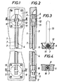
- a directional fitting 4 is fitted in recesses 2 and a groove 3 connecting a door leaf side surface, which consists of two anchor pieces 5, 6 and one in the recesses 2 with one in the recesses 2 Cover bar not shown, coverable groove 3 from anchor piece to anchor piece continuous threaded rod 7.
- the threaded rod 7 is supported on both ends of the anchor pieces 5, 6, for which purpose it engages in the anchor piece 5 in a non-rotatably and axially immovable nut 8 and in the anchor piece 6 in an axially non-displaceable but rotatably arranged nut 9.
- the anchor piece 5 forms a blind hole 10 for threaded rod 7, so that the threaded rod screwed into the possibly self-locking nut 8 as far as possible is held securely in the anchor piece 5.
- the anchor piece 6, on the other hand, has a through hole 11 for the threaded rod 7, as a result of which the threaded rod 7 can be screwed into the nut 9 as far as desired and can also be adjusted longitudinally with respect to the anchor piece 6 practically without restriction by turning the nut 9.
- a transverse slot 12 is provided in the anchor piece 6, which, as indicated in FIG. 3, allows a wrench 13 to be attached to the nut 9 and enables the directional fitting 3 to be actuated easily.
- the threaded rod 7 held in the anchor piece 5 is axially adjusted and, depending on whether the distance between the anchor pieces 5, 6 is shortened or lengthened, a tensile or compressive force on the door leaf 1 exercised, which ensures a straight bending of the door leaf 1 in the event of a delay.
- the directional fitting 4 according to the invention consists of simple parts which can be produced and assembled with little effort. It can be installed in just a few simple steps and can be easily adapted to the prevailing conditions by selecting or cutting the threaded rod to length, which is also a functionally reliable, effortless actuation option using a conventional wrench.
Landscapes
- Engineering & Computer Science (AREA)
- Architecture (AREA)
- Civil Engineering (AREA)
- Structural Engineering (AREA)
- Joining Of Building Structures In Genera (AREA)
- Securing Of Glass Panes Or The Like (AREA)
Applications Claiming Priority (2)
| Application Number | Priority Date | Filing Date | Title |
|---|---|---|---|
| AT350785A AT382929B (de) | 1985-12-03 | 1985-12-03 | Richtbeschlag zum geradebiegen verzogener tueren od. dgl. |
| AT3507/85 | 1985-12-03 |
Publications (3)
| Publication Number | Publication Date |
|---|---|
| EP0225312A2 true EP0225312A2 (fr) | 1987-06-10 |
| EP0225312A3 EP0225312A3 (en) | 1988-05-04 |
| EP0225312B1 EP0225312B1 (fr) | 1990-09-05 |
Family
ID=3551468
Family Applications (1)
| Application Number | Title | Priority Date | Filing Date |
|---|---|---|---|
| EP19860890318 Expired - Lifetime EP0225312B1 (fr) | 1985-12-03 | 1986-11-14 | Garniture d'ajustage pour dégauchir les portes déformées ou similaires |
Country Status (3)
| Country | Link |
|---|---|
| EP (1) | EP0225312B1 (fr) |
| AT (1) | AT382929B (fr) |
| DE (1) | DE3673963D1 (fr) |
Cited By (5)
| Publication number | Priority date | Publication date | Assignee | Title |
|---|---|---|---|---|
| FR2704583A1 (fr) * | 1993-04-29 | 1994-11-04 | Eku Ag | Ferrure d'alignement pour une porte coulissante. |
| CN108714635A (zh) * | 2018-05-18 | 2018-10-30 | 中山市博瑞特家居科技有限公司 | 一种竖直门板矫正器 |
| CN108723118A (zh) * | 2018-07-24 | 2018-11-02 | 刘韦明 | 门板拉直器 |
| IT201700057159A1 (it) * | 2017-05-25 | 2018-11-25 | Otlav Spa | Tirante per raddrizzare un’anta e metodo per montare detto tirante su un'anta |
| CN113513142A (zh) * | 2021-06-24 | 2021-10-19 | 中国一冶集团有限公司 | 一种预制凸窗的校正装置及采用该装置的校正方法 |
Families Citing this family (1)
| Publication number | Priority date | Publication date | Assignee | Title |
|---|---|---|---|---|
| EP3722549B1 (fr) * | 2019-04-08 | 2023-06-21 | Baugruppentechnik Pollmeier GmbH | Ferrure d'alignement |
Family Cites Families (6)
| Publication number | Priority date | Publication date | Assignee | Title |
|---|---|---|---|---|
| US3286424A (en) * | 1965-01-04 | 1966-11-22 | Romer G Weyant | Door construction |
| FR2270432A1 (en) * | 1974-03-29 | 1975-12-05 | Gimm Gprt Indl Manuf Menuiseri | Door or window with anti-warp bars - has tension or compression screw assemblies at one end of each bar |
| AT350776B (de) * | 1976-02-10 | 1979-06-25 | Burgauer Moebelfabrik Dkfm P P | Vorrichtung zum planbiegen verworfener tuer- blaetter od.dgl. |
| DE3102756A1 (de) * | 1980-02-01 | 1982-01-07 | Alois 4020 Linz Mayerhofer | Vorrichtung zum planrichten verworfener oder gewoelbter platten |
| DE3230803A1 (de) * | 1982-08-19 | 1984-02-23 | Aktiengesellschaft Conrad Zschokke Isolationen, 8752 Näfels | Vorrichtung zum ausrichten von verzogenen gegenstaenden, insbesondere von eingangstueren |
| DE3416784C2 (de) * | 1983-12-19 | 1987-02-19 | Kurt Franz GmbH, Holzwarenfabrikation, 8641 Tettau | Türblatt mit einer Richtvorrichtung |
-
1985
- 1985-12-03 AT AT350785A patent/AT382929B/de not_active IP Right Cessation
-
1986
- 1986-11-14 DE DE8686890318T patent/DE3673963D1/de not_active Expired - Lifetime
- 1986-11-14 EP EP19860890318 patent/EP0225312B1/fr not_active Expired - Lifetime
Cited By (7)
| Publication number | Priority date | Publication date | Assignee | Title |
|---|---|---|---|---|
| FR2704583A1 (fr) * | 1993-04-29 | 1994-11-04 | Eku Ag | Ferrure d'alignement pour une porte coulissante. |
| IT201700057159A1 (it) * | 2017-05-25 | 2018-11-25 | Otlav Spa | Tirante per raddrizzare un’anta e metodo per montare detto tirante su un'anta |
| EP3406824A1 (fr) * | 2017-05-25 | 2018-11-28 | OTLAV SpA | Tirant et procédé de montage de celui-ci |
| CN108714635A (zh) * | 2018-05-18 | 2018-10-30 | 中山市博瑞特家居科技有限公司 | 一种竖直门板矫正器 |
| CN108723118A (zh) * | 2018-07-24 | 2018-11-02 | 刘韦明 | 门板拉直器 |
| CN113513142A (zh) * | 2021-06-24 | 2021-10-19 | 中国一冶集团有限公司 | 一种预制凸窗的校正装置及采用该装置的校正方法 |
| CN113513142B (zh) * | 2021-06-24 | 2022-07-15 | 中国一冶集团有限公司 | 一种预制凸窗的校正装置及采用该装置的校正方法 |
Also Published As
| Publication number | Publication date |
|---|---|
| AT382929B (de) | 1987-04-27 |
| ATA350785A (de) | 1986-09-15 |
| EP0225312A3 (en) | 1988-05-04 |
| EP0225312B1 (fr) | 1990-09-05 |
| DE3673963D1 (de) | 1990-10-11 |
Similar Documents
| Publication | Publication Date | Title |
|---|---|---|
| EP0645282B1 (fr) | Pied de support de l'extrémité d'un profilé de galerie sur un toit de véhicule | |
| DE2614447A1 (de) | Scharnier | |
| DE4200096C2 (de) | Vorrichtung zum Verschließen einer Öffnung in einer Verkleidung | |
| EP0225312A2 (fr) | Garniture d'ajustage pour dégauchir les portes déformées ou similaires | |
| DE19619869C2 (de) | Außenbetätigung für einen Fahrzeug-Türverschluß | |
| EP0458777B1 (fr) | Serrure à cylindre | |
| DE3140855C2 (de) | Vorrichtung zum Betätigen einer Ausstellschere für die Flügel von Fenstern, Türen oder dergleichen | |
| EP2578891B1 (fr) | Adapteur | |
| DE19848071A1 (de) | Anordnungsvorrichtung für einen Öldruck-Türschließer | |
| DE202006014335U1 (de) | Vorrichtung zum Fixieren eines Baukörpers in einer Gebäudeöffnung | |
| DE3604326A1 (de) | Vorrichtung zur befestigung eines rohres an einer wand | |
| DE2505176B2 (de) | Wischblatt fuer kraftfahrzeug-wischanlagen | |
| DE1276496B (de) | Befestigung eines Kupplungsgliedes an einer Treibstange von Treibstangenbeschlaegen fuer Fenster, Tueren od. dgl. | |
| EP0932175A2 (fr) | Actionneur pivotable pour interrupteur de sécurité | |
| DE3940926C2 (de) | Demontierbares Türscharnier für Kraftfahrzeugtüren | |
| DE102004034144A1 (de) | Mitnehmer zur Befestigung einer Fensterscheibe eines Kraftfahrzeuges an einer Führungseinrichtung eines Fensterhebers | |
| EP0773397B1 (fr) | Support de conduite | |
| DE3014818C2 (de) | Christbaumständer mit einer Wasserschale | |
| DE10154990B4 (de) | Verbindungsvorrichtung für Geländer | |
| DE2248576C3 (de) | Rastbolzen zum Festlegen einer Leiste an einem Fensterrahmen, Türrahmen o.dgl | |
| DE3809281A1 (de) | Bowdenzug mit spieljustierung des seiles | |
| EP1464767B1 (fr) | Dispositif pour fixer un accessoire sanitaire à un mur | |
| CH648896A5 (de) | Aufhaengevorrichtung fuer tore. | |
| EP1223263B1 (fr) | Dispositif d'assemblage pour balustrades | |
| DE102023112864A1 (de) | Beschlag für Türen oder Fenster |
Legal Events
| Date | Code | Title | Description |
|---|---|---|---|
| PUAI | Public reference made under article 153(3) epc to a published international application that has entered the european phase |
Free format text: ORIGINAL CODE: 0009012 |
|
| AK | Designated contracting states |
Kind code of ref document: A2 Designated state(s): BE CH DE FR GB IT LI LU NL SE |
|
| PUAL | Search report despatched |
Free format text: ORIGINAL CODE: 0009013 |
|
| AK | Designated contracting states |
Kind code of ref document: A3 Designated state(s): BE CH DE FR GB IT LI LU NL SE |
|
| 17P | Request for examination filed |
Effective date: 19880622 |
|
| 17Q | First examination report despatched |
Effective date: 19891027 |
|
| GRAA | (expected) grant |
Free format text: ORIGINAL CODE: 0009210 |
|
| AK | Designated contracting states |
Kind code of ref document: B1 Designated state(s): BE CH DE FR GB IT LI LU NL SE |
|
| REF | Corresponds to: |
Ref document number: 3673963 Country of ref document: DE Date of ref document: 19901011 |
|
| ITF | It: translation for a ep patent filed | ||
| ITTA | It: last paid annual fee | ||
| ET | Fr: translation filed | ||
| GBT | Gb: translation of ep patent filed (gb section 77(6)(a)/1977) | ||
| PLBE | No opposition filed within time limit |
Free format text: ORIGINAL CODE: 0009261 |
|
| STAA | Information on the status of an ep patent application or granted ep patent |
Free format text: STATUS: NO OPPOSITION FILED WITHIN TIME LIMIT |
|
| 26N | No opposition filed | ||
| EPTA | Lu: last paid annual fee | ||
| EAL | Se: european patent in force in sweden |
Ref document number: 86890318.8 |
|
| PGFP | Annual fee paid to national office [announced via postgrant information from national office to epo] |
Ref country code: SE Payment date: 19981030 Year of fee payment: 13 |
|
| PGFP | Annual fee paid to national office [announced via postgrant information from national office to epo] |
Ref country code: GB Payment date: 19981102 Year of fee payment: 13 |
|
| PGFP | Annual fee paid to national office [announced via postgrant information from national office to epo] |
Ref country code: NL Payment date: 19981125 Year of fee payment: 13 |
|
| PGFP | Annual fee paid to national office [announced via postgrant information from national office to epo] |
Ref country code: LU Payment date: 19981208 Year of fee payment: 13 |
|
| PG25 | Lapsed in a contracting state [announced via postgrant information from national office to epo] |
Ref country code: LU Free format text: LAPSE BECAUSE OF NON-PAYMENT OF DUE FEES Effective date: 19991114 Ref country code: GB Free format text: LAPSE BECAUSE OF NON-PAYMENT OF DUE FEES Effective date: 19991114 |
|
| PG25 | Lapsed in a contracting state [announced via postgrant information from national office to epo] |
Ref country code: SE Free format text: LAPSE BECAUSE OF NON-PAYMENT OF DUE FEES Effective date: 19991115 |
|
| PG25 | Lapsed in a contracting state [announced via postgrant information from national office to epo] |
Ref country code: NL Free format text: LAPSE BECAUSE OF NON-PAYMENT OF DUE FEES Effective date: 20000601 |
|
| GBPC | Gb: european patent ceased through non-payment of renewal fee |
Effective date: 19991114 |
|
| EUG | Se: european patent has lapsed |
Ref document number: 86890318.8 |
|
| NLV4 | Nl: lapsed or anulled due to non-payment of the annual fee |
Effective date: 20000601 |
|
| PGFP | Annual fee paid to national office [announced via postgrant information from national office to epo] |
Ref country code: FR Payment date: 20051122 Year of fee payment: 20 |
|
| PGFP | Annual fee paid to national office [announced via postgrant information from national office to epo] |
Ref country code: IT Payment date: 20051129 Year of fee payment: 20 Ref country code: DE Payment date: 20051129 Year of fee payment: 20 |
|
| PGFP | Annual fee paid to national office [announced via postgrant information from national office to epo] |
Ref country code: CH Payment date: 20051202 Year of fee payment: 20 |
|
| PGFP | Annual fee paid to national office [announced via postgrant information from national office to epo] |
Ref country code: BE Payment date: 20051216 Year of fee payment: 20 |
|
| REG | Reference to a national code |
Ref country code: CH Ref legal event code: PL |
|
| BE20 | Be: patent expired |
Owner name: *MAYERHOFER ALOIS Effective date: 20061114 |