EP3406824A1 - Tirant et procédé de montage de celui-ci - Google Patents
Tirant et procédé de montage de celui-ci Download PDFInfo
- Publication number
- EP3406824A1 EP3406824A1 EP18174132.3A EP18174132A EP3406824A1 EP 3406824 A1 EP3406824 A1 EP 3406824A1 EP 18174132 A EP18174132 A EP 18174132A EP 3406824 A1 EP3406824 A1 EP 3406824A1
- Authority
- EP
- European Patent Office
- Prior art keywords
- panel
- rod
- door
- shutter
- tie rod
- Prior art date
- Legal status (The legal status is an assumption and is not a legal conclusion. Google has not performed a legal analysis and makes no representation as to the accuracy of the status listed.)
- Granted
Links
Images


Classifications
-
- E—FIXED CONSTRUCTIONS
- E06—DOORS, WINDOWS, SHUTTERS, OR ROLLER BLINDS IN GENERAL; LADDERS
- E06B—FIXED OR MOVABLE CLOSURES FOR OPENINGS IN BUILDINGS, VEHICLES, FENCES OR LIKE ENCLOSURES IN GENERAL, e.g. DOORS, WINDOWS, BLINDS, GATES
- E06B9/00—Screening or protective devices for wall or similar openings, with or without operating or securing mechanisms; Closures of similar construction
- E06B9/02—Shutters, movable grilles, or other safety closing devices, e.g. against burglary
- E06B9/06—Shutters, movable grilles, or other safety closing devices, e.g. against burglary collapsible or foldable, e.g. of the bellows or lazy-tongs type
- E06B9/0607—Shutters, movable grilles, or other safety closing devices, e.g. against burglary collapsible or foldable, e.g. of the bellows or lazy-tongs type comprising a plurality of similar rigid closing elements movable to a storage position
- E06B9/0615—Shutters, movable grilles, or other safety closing devices, e.g. against burglary collapsible or foldable, e.g. of the bellows or lazy-tongs type comprising a plurality of similar rigid closing elements movable to a storage position characterised by the closing elements
- E06B9/0638—Slats or panels
-
- E—FIXED CONSTRUCTIONS
- E04—BUILDING
- E04F—FINISHING WORK ON BUILDINGS, e.g. STAIRS, FLOORS
- E04F21/00—Implements for finishing work on buildings
- E04F21/0007—Implements for finishing work on buildings for mounting doors, windows or frames; their fitting
-
- E—FIXED CONSTRUCTIONS
- E06—DOORS, WINDOWS, SHUTTERS, OR ROLLER BLINDS IN GENERAL; LADDERS
- E06B—FIXED OR MOVABLE CLOSURES FOR OPENINGS IN BUILDINGS, VEHICLES, FENCES OR LIKE ENCLOSURES IN GENERAL, e.g. DOORS, WINDOWS, BLINDS, GATES
- E06B3/00—Window sashes, door leaves, or like elements for closing wall or like openings; Layout of fixed or moving closures, e.g. windows in wall or like openings; Features of rigidly-mounted outer frames relating to the mounting of wing frames
- E06B3/70—Door leaves
- E06B3/7015—Door leaves characterised by the filling between two external panels
- E06B3/7017—Door leaves characterised by the filling between two external panels of grating type
-
- E—FIXED CONSTRUCTIONS
- E06—DOORS, WINDOWS, SHUTTERS, OR ROLLER BLINDS IN GENERAL; LADDERS
- E06B—FIXED OR MOVABLE CLOSURES FOR OPENINGS IN BUILDINGS, VEHICLES, FENCES OR LIKE ENCLOSURES IN GENERAL, e.g. DOORS, WINDOWS, BLINDS, GATES
- E06B3/00—Window sashes, door leaves, or like elements for closing wall or like openings; Layout of fixed or moving closures, e.g. windows in wall or like openings; Features of rigidly-mounted outer frames relating to the mounting of wing frames
- E06B3/70—Door leaves
- E06B3/82—Flush doors, i.e. with completely flat surface
- E06B3/822—Flush doors, i.e. with completely flat surface with an internal foursided frame
- E06B3/825—Flush doors, i.e. with completely flat surface with an internal foursided frame with a wooden frame
-
- E—FIXED CONSTRUCTIONS
- E06—DOORS, WINDOWS, SHUTTERS, OR ROLLER BLINDS IN GENERAL; LADDERS
- E06B—FIXED OR MOVABLE CLOSURES FOR OPENINGS IN BUILDINGS, VEHICLES, FENCES OR LIKE ENCLOSURES IN GENERAL, e.g. DOORS, WINDOWS, BLINDS, GATES
- E06B3/00—Window sashes, door leaves, or like elements for closing wall or like openings; Layout of fixed or moving closures, e.g. windows in wall or like openings; Features of rigidly-mounted outer frames relating to the mounting of wing frames
- E06B3/96—Corner joints or edge joints for windows, doors, or the like frames or wings
- E06B3/964—Corner joints or edge joints for windows, doors, or the like frames or wings using separate connection pieces, e.g. T-connection pieces
- E06B3/9649—Tie rods spanning the whole width or height of the frame; Straps encircling the frame
-
- E—FIXED CONSTRUCTIONS
- E06—DOORS, WINDOWS, SHUTTERS, OR ROLLER BLINDS IN GENERAL; LADDERS
- E06B—FIXED OR MOVABLE CLOSURES FOR OPENINGS IN BUILDINGS, VEHICLES, FENCES OR LIKE ENCLOSURES IN GENERAL, e.g. DOORS, WINDOWS, BLINDS, GATES
- E06B5/00—Doors, windows, or like closures for special purposes; Border constructions therefor
- E06B5/006—Doors, windows, or like closures for special purposes; Border constructions therefor for furniture
-
- E—FIXED CONSTRUCTIONS
- E06—DOORS, WINDOWS, SHUTTERS, OR ROLLER BLINDS IN GENERAL; LADDERS
- E06B—FIXED OR MOVABLE CLOSURES FOR OPENINGS IN BUILDINGS, VEHICLES, FENCES OR LIKE ENCLOSURES IN GENERAL, e.g. DOORS, WINDOWS, BLINDS, GATES
- E06B9/00—Screening or protective devices for wall or similar openings, with or without operating or securing mechanisms; Closures of similar construction
- E06B9/02—Shutters, movable grilles, or other safety closing devices, e.g. against burglary
- E06B9/04—Shutters, movable grilles, or other safety closing devices, e.g. against burglary of wing type, e.g. revolving or sliding
Definitions
- the present invention refers to a tie rod for straightening a door/panel/shutter and to a method for mounting said tie rod on a door/panel/shutter, according to the preamble of the respective main independent claims.
- the present tie rod is intended to be employed in the field of production of doors/windows and in particular of production of wooden doors and similar materials (such as hollow-core panels or multilayer sandwich of different materials) or even in the field of interior decoration for producing doors/panels/shutters of furniture pieces, for the purpose of flattening the profile of the doors/panels/shutters if it no longer has the condition of planarity, given that it has been warped in an aesthetically and/or functionally undesired manner.
- the tie rod is susceptible of being employed with doors/panels/shutters of any type, both slidable and shutter, and of any size in order to correct undesired deformations; in particular, it is advantageously intended to be mounted on large-size doors/panels/shutters i.e. on doors/panels/shutters produced with materials and production processes that are inexpensive or in any case unsuitable for ensuring the non-deformability thereof over time.
- the tie rod, object of the present invention is therefore generally inserted in the industrial field of production of doors/windows and in the field of production of interior decoration articles, i.e. also in the field of production of metal accessories for doors or furniture pieces.
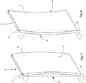
- the doors/panels/shutters can be warped or deformed over time, assuming a concave form on an internal or external face of the door/panel/shutter; for example a door can assume a convexity towards the interior of a room or towards the outside thereof.
- Such deformation in addition to being aesthetically unacceptable, may compromise the perfect functionality of the door/panel/shutter, for example preventing a perfect closure or a perfect sealing on a provided seal of the fixed frame.
- the deformation mainly takes place at the free edge opposite that constrained, at which the hinges are associated for connection to the door frame or to the upright of the door/panel/shutter of the furniture piece, since the hinges oblige at least a partial alignment with such constrained edge.
- the causes of such deformation are first of all ascribable to the production process of the door/panel/shutter and to the tensions that start in particular following the gluing steps, especially if attained with hot pressing and/or with quick production cycles.
- the doors for interiors are generally constituted by a hollow-core panel or by a sandwich composed of: two more external panels, e.g. made of chipboard, MDF or plywood, by a perimeter frame, e.g. made of solid wood (e.g. fir, but otherwise also of derivative wood-based materials such as chip) and by a light honeycomb-shaped structure which is inserted within the frame, e.g. made of cardboard, as spacer of the two external reinforcement panels of the door.
- the two external panels are usually glued on the frame with cold or hot pressing.
- the sandwich thus made is a raw manufactured product which is then covered with very thin wood sheets or with laminated sheets for making doors of wood or laminate. Otherwise, the sandwich is directly painted in the various finishes in order to make, for example, lacquered doors.
- the gluing of the panels to the frame can involve the generation of internal pressures between the different glued fibers, which over time lead to the warping of the door/panel/shutter.
- a further cause of deformation of the door/panel/shutter can be traced to the presence of temperature and/or humidity differences existing between the two sides of the door/panel/shutter.
- the internal face of the door directed for example towards a room can be subjected to environmental conditions different from that of the external face directed for example towards a hallway or kitchen.
- deformation is also encountered quite often in the case of large-size doors/panels/shutters, in which a small angle of the panel can lead to a large-size deformation at the center of the door/panel/shutter.
- Deformations are more easily encountered also in the case of inexpensive products, i.e. in the case of use of light materials with low mechanical strength, as in the case of wood seasoned poorly or for a short time period.
- tie rods for straightening the doors/panels/shutters are widespread on the market; such tie rods are associated in a non-centered manner with respect to the middle plane or with an internal face or with an external face of the door/panel/shutter and in a visible position or embedded within the thickness of the door/panel/shutter.
- Such tie rods consist of a rod which is associated at the ends with two bodies for engaging the panel of the door/panel/shutter.
- a screw/nut screw mechanism interposed on the rod or associated with the connection between rod and engagement bodies, it is thus possible to force - by moving apart or approaching - the two engagement bodies so as to move apart or approach the upper and lower ends of the door/panel/shutter and consequently act on the position of the plane with which the tie rod is associated, respectively in order to compensate for a concavity or convexity.
- the tie rod comprises a rod composed of two segments, each associated at a first end with an intermediate screw / nut screw mechanism and at the other second end with a respective engagement body embedded in a seat of the panel of the door/panel/shutter.
- Each segment is axially engaged with the respective engagement body and is free to rotate with respect to its axial extension axis.
- At least one rod segment continues beyond the engagement body, being accessible with its second free end at the upper and/or lower thickness of the door/panel/shutter for an easy adjustment.
- Such second end has for such purpose an impression for receiving a tool such as a wrench or Allen wrench or a screwdriver with which it is possible to rotate the rod segment and consequently determine the screwing or unscrewing of its first end with respect to the screw / nut screw mechanism.
- a tool such as a wrench or Allen wrench or a screwdriver with which it is possible to rotate the rod segment and consequently determine the screwing or unscrewing of its first end with respect to the screw / nut screw mechanism.
- the tie rod comprises a rod made of a single body, which terminates at the two ends with nut screws, each adjustably engaged by screws whose head is rotatably housed in a seat made of a corresponding engagement body integral with the panel of the door/panel/shutter.
- the heads of the screws are accessible by a milling made in the upper or lower thickness of the door/panel/shutter.
- the tie rod comprises two engagement bodies embedded in seats made on an internal face, not visible, of the door/panel/shutter and joined together by a rod which runs on the surface of the of the door/panel/shutter and is divided into two segments by a screw / nut screw mechanism.
- the latter comprises a bush, which is engaged at its two ends to the threaded ends of the two rod segments and is externally accessible with a wrench in order to be rotated so as to pull or push the two engagement bodies close to or away from each other.
- doors/panels/shutters for example the doors/panels/shutters for the interior doors
- doors/panels/shutters for example the doors/panels/shutters for the interior doors
- length that generally can vary between about 2 meters and about 3 meters. Therefore, such different sizes of doors require tie rods with height corresponding to the door model.
- the problem underlying the present invention is to overcome the drawbacks of the abovementioned prior art, by providing a tie rod for straightening a door/panel/shutter which is easily adaptable to the different sizes of doors/panels/shutters existing on the market, without requiring complex adaptation operations.
- a further object of the present invention is to provide a tie rod for straightening a door/panel/shutter, which is simple and inexpensive to attain.
- a further object of the present invention is to provide a method for mounting a tie rod on a door/panel/shutter which does not require complex and costly adaptations in order to be mounted on doors/panels/shutters of different size.
- a further object of the present invention is to provide a tie rod for straightening a door/panel/shutter and a method for the mounting thereof, which are safe and entirely reliable in operation.
- reference number 1 overall indicates a tie rod for straightening a door/panel/shutter, object of the present invention.
- the tie rod 1 according to the invention is intended to be employed for bringing back to planarity the panels of doors/panels/shutters of doors or furniture pieces which - due to environmental or production causes - may have lost the perfect planarity of their position after their production or even after years.
- tie rod according to the invention can be applied on doors/panels/shutters and walls of different type such as of cupboards/cabinets, partitions etc.
- the tie rod 1 according to the present invention is therefore generally susceptible of being employed with doors/panels/shutters of any type, whether slidable or hinged, in order to correct undesired deformations and in particular it is advantageously intended to be mounted on large-size doors/panels/shutters or on doors/panels/shutters produced with materials and production processes unsuitable for ensuring the non-deformability over time, as can occur for example in the case of hollow-core panels for doors obtained with multilayer sandwich of different materials.
- the door/panel/shutter of a door 2 (but sometimes also of a furniture piece) generally comprises a panel 3, for example constituted by a multilayer sandwich, which defines an internal face 4 and an external face 5, that are parallel to each other and separated by a thickness S which delimits an upper edge 7, a lower edge 8 as well as two lateral edges 9, 10, including a first constrained edge 9 connected to the frame of the door/panel/shutter (or to the upright of the furniture piece) by means of hinges, and a second free edge 10, which is parallel to and opposite the first constrained edge 9 (see figure 12 ).
- a panel 3 for example constituted by a multilayer sandwich, which defines an internal face 4 and an external face 5, that are parallel to each other and separated by a thickness S which delimits an upper edge 7, a lower edge 8 as well as two lateral edges 9, 10, including a first constrained edge 9 connected to the frame of the door/panel/shutter (or to the upright of the furniture piece) by means of hinges, and a second free edge
- the panel 3 is substantially extended in a mirrored manner with respect to a middle longitudinal plane P with its two flat and parallel faces equidistant from such plane (in figure 12 the plane P is indicated with a dash/dot line and its projection on the thickness S of the panel is indicated with a dotted line).
- the tie rod 1 also comprises, in a per se known manner, at least two engagement bodies 11, intended to be mechanically embedded in the panel 3 of the door/panel/shutter 2 in a non-centered manner with respect to the middle plane P of the same panel 3, i.e. arranged closer to one of the two internal or external faces of the door/panel/shutter 2.
- tie rods 1 are usually provided for each door/panel/shutter arranged at its two lateral edges 9 and 10.
- the tie rod 1 also has at least one rod 12, provided with a main extension that is substantially axial Y, which is axially mechanically connected at its first ends 13 to the two engagement bodies 11.
- Screw / nut screw means 14 are then provided for lengthening and shortening the length of the rod 12 subtended between the two engagement bodies 11, in order to adjust the tension of the tie rod and consequently straighten the door/panel/shutter.
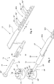
- the rod 12 comprises at least one first and one second rod segment 12A, 12B, which are provided, for the length of corresponding first and second sections 15A, 15B of their axial extension, with respective first and second shaped profiles 16A, 16B, which are mechanically couplable with each other with shape coupling for a variable shared section 17.
- rod segments 12A, 12B equivalent to each other (for example about 1.30-1.50 m), which can then be differently connected to each other in order to obtain tie rods susceptible of being employed for all door sizes.
- a tie rod is obtained that is very long for very high doors, for example up to 3 meters; by coupling two tie rods, arranging a very long shared section, a tie rod is thus obtained that is very short for very low doors, for example with 2 meters height.
- the first and the second shaped profiles 16A, 16B advantageously alternate the shape of a male element 16' with the shape of a female seat 16", along the axial extension Y of their respective first and second sections 15A, 15B.
- the male elements 16' of the two shaped profiles 16A, 16B are inserted in the female seats 16" of the other facing shaped profile 16A, 16B in order to render the two segments 12A, 12B of rod 12 (see figures 1 and 2 ) axially integral.
- the pitch R between the male elements 16' or between the female seats 16" can be 10 mm such that the length of the rod can vary at intervals of 10 mm and be able to form, with two rod segments 12A, 12B of about a meter and a half each, tie rods for doors with height comprised between 2 meters and 3 meters.
- the form of the shaped profiles 16A, 16B - i.e. of the male elements 16' and of the female seats 16" - can be quite varied, able to provide for sawtooth or lobe solutions as in the case illustrated in the enclosed figures.
- the two shaped profiles 16A, 16B define, in the shared section 17 in which they are coupled, a cross section which is substantially unchanged with respect to that of the parts of rod segments 12A, 12B in which the shaped profiles 16A, 16B are not present.
- the provided milling made in the panel 3 which serves to maintain - assembled and guided - the two rod segments 12A, 12B with the shaped profiles 16A, 16B coupled together for the shared section 17, can be made with regular shape for the entire distance that separates the seats in the panel of the door/panel/shutter for the two engagement bodies 11.
- the rod segments 12A, 12B have the form of elongated plates with the sections bearing the first and the second profile 16A, 16B with reduced width.
- such elongated plates of the two rod segments 12A, 12B define in the shared section 17, in which the two shaped profiles 16A, 16B are coupled, substantially the same cross section that the elongated plates of the rod segments 12A, 12B define in the sections lacking the corresponding shaped profile 16A, 16B.
- the lateral edges of the rod 12 are substantially parallel for their entire axial extension such that the milling on the panel is correspondingly constituted by a groove with width and depth equal to the width and thickness of the rod 12.
- first and the second shaped profile 16A, 16B of the rod segments 12A, 12B are susceptible of being retained coupled with their shared section 17 which actually constrains them, within the groove obtained flush on the panel 3 of the door/panel/shutter 2.
- the screw / nut screw means 14, mentioned above, comprise at least one screw 19 (see figures 3 and 4 ) provided with a shank 19', engaged in a nut screw 20 constrained to at least one first end 13 of a rod segment 12A, 12B, and with a head 19" rotatably housed in a seat 21 made in a corresponding engagement body 11.
- the engagement bodies 11 are obtained in a pressure die-cast body made of zamak with the seat 21 for the head 19" of the screw which is continued with a neck 22. Within the latter, the initial part of the shank 19' of the screw 19 is housed.
- the body made of zamak of the engagement body 11 also comprises a semi-annular seat 22' side-by-side the seat 21 in order to support the shank of the screw 19 in a rotatable and axially centered manner.
- the screw/nut screw means 14 also comprise a bush 23, which is fixed to the first end 13 of the rod segment 12A, 12B and bears, obtained at a termination axially directed towards the engagement body 11, the aforesaid nut screw 20.
- the bush 23 is advantageously made of metal and is fixed for example by means of a weld to the first end 13 of the relative segment 12A, 12B of rod 12 with the axis of the bush 23, i.e. the axis of the nut screw 20, parallel to the axial extension Y of the rod 12.
- the milling 32 on the panel is extended up to reaching the upper and/or lower edge 7, 8 of the panel 3 of the door/panel/shutter 2 in order to allow the access with a tool U to the head 19" of the screw 19 and hence to be able to rotate and thus cause the tightening of the panel 3, bringing it back to planarity if an undesired deformation thereof has occurred.
- Also forming the object of the present invention is a method for mounting the above-described tie rod on a door/panel/shutter 2, regarding which the same nomenclature introduced up to now will be maintained hereinbelow for the sake of description simplicity.
- the method provides for an initial step of arranging a panel 3 of a door/panel/shutter 2 composed of a sandwich formed by at least two external parallel laminar layers 30 (e.g. made of MDF) with a perimeter frame 31 (e.g. made of solid wood, such as fir) interposed therebetween.
- a panel 3 of a door/panel/shutter 2 composed of a sandwich formed by at least two external parallel laminar layers 30 (e.g. made of MDF) with a perimeter frame 31 (e.g. made of solid wood, such as fir) interposed therebetween.
- honeycomb-like filler material 35 could for example be inserted, which is very light and susceptible of giving structure to the door/panel/shutter 2.
- At least one of the two external laminar layers 30 is separated from the remaining sandwich structure part of the panel 3, i.e. it is separated from the frame 31.
- the perimeter frame 31 of the panel 3 is provided with two parallel uprights 31A and with two parallel crosspieces 31B which are joined to the uprights at the respective ends in order to form the frame 31 in the shape of a quadrangular frame, in particular rectangular frame.
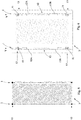
- two corresponding shaped millings 32 are made, which have, in vicinity to the upper and lower ends of the uprights 31A (i.e. in vicinity to the upper and lower edges 7, 8 of the panels 30), two seats 33 for housing the engagement bodies 11.
- Such seats 33 are separated from each other by a first distance D1 ( figure 9 ) and are connected together by a groove 34 that continues beyond at least one of the two seats 33 (and preferably beyond both seats 33) up to a corresponding upper or lower edge 7, 8 of the panel 3, in order to render the seat 33 of the engagement body 11 accessible from the edge of the same panel 3 (hence through a terminal milling) for example by means of a screwdriver, a wrench of another tool.
- the groove can have different depths in order to house the flat sections of the rod segments 12A, 12B and the sections at the first ends 13 in which the bushes 23 are fixed below.
- the tie rod 1 thus assembled is inserted in the milling 32 with the rod 12 composed of the two coupled segments 12A, 12B (and of the two bushes) which is flush-inserted in the groove 34 of the frame 31 of the panel 3 and with the engagement bodies 11, axially mechanically connected to the first ends 13 of the rod 12, which are flush-inserted in the seats 33 of the milling 32 of the frame 21.
- tie rods 1 are provided for each door/panel/shutter 2; nevertheless, even only one tie rod could be employed, or more than two tie rods could be employed, such as three tie rods, including two placed at the lateral edges 9, 10 of the door/panel/shutter 2 and one placed at the center of the door/panel/shutter 2.
- the finding thus conceived therefore attains the pre-established objects.
Landscapes
- Engineering & Computer Science (AREA)
- Structural Engineering (AREA)
- Civil Engineering (AREA)
- Architecture (AREA)
- Securing Of Glass Panes Or The Like (AREA)
- Operating, Guiding And Securing Of Roll- Type Closing Members (AREA)
Priority Applications (1)
| Application Number | Priority Date | Filing Date | Title |
|---|---|---|---|
| PL18174132T PL3406824T3 (pl) | 2017-05-25 | 2018-05-24 | Pręt cięgnowy i sposób jego mocowania |
Applications Claiming Priority (1)
| Application Number | Priority Date | Filing Date | Title |
|---|---|---|---|
| IT102017000057159A IT201700057159A1 (it) | 2017-05-25 | 2017-05-25 | Tirante per raddrizzare un’anta e metodo per montare detto tirante su un'anta |
Publications (2)
| Publication Number | Publication Date |
|---|---|
| EP3406824A1 true EP3406824A1 (fr) | 2018-11-28 |
| EP3406824B1 EP3406824B1 (fr) | 2020-03-11 |
Family
ID=60020477
Family Applications (1)
| Application Number | Title | Priority Date | Filing Date |
|---|---|---|---|
| EP18174132.3A Active EP3406824B1 (fr) | 2017-05-25 | 2018-05-24 | Tirant et procédé de montage de celui-ci |
Country Status (3)
| Country | Link |
|---|---|
| EP (1) | EP3406824B1 (fr) |
| IT (1) | IT201700057159A1 (fr) |
| PL (1) | PL3406824T3 (fr) |
Cited By (2)
| Publication number | Priority date | Publication date | Assignee | Title |
|---|---|---|---|---|
| GB2594092A (en) * | 2020-04-17 | 2021-10-20 | Garner Aluminium Extrusions Ltd | A tie |
| EP4400687A1 (fr) * | 2023-01-12 | 2024-07-17 | Häfele SE & Co KG | Ferrure d'alignement pour l'alignement d'un vantail de porte ainsi que vantail et procédé d'assemblage d'une ferrure d'alignement associés |
Citations (4)
| Publication number | Priority date | Publication date | Assignee | Title |
|---|---|---|---|---|
| EP0225312A2 (fr) * | 1985-12-03 | 1987-06-10 | Alois Mayerhofer | Garniture d'ajustage pour dégauchir les portes déformées ou similaires |
| DE8708885U1 (de) * | 1987-06-26 | 1987-08-20 | Wagner, Bodo, 8222 Ruhpolding | Verstellbare Verzugsicherung |
| DE29622285U1 (de) * | 1996-12-21 | 1997-04-17 | Höhbauer GmbH, 92706 Luhe-Wildenau | Spann- oder Richtvorrichtung sowie Türblatt bzw. Türflügel für Gebäudetüren mit einer solchen Spannvorrichtung |
| EP2385209A2 (fr) * | 2010-05-07 | 2011-11-09 | Mario Pilsl | Dispositif de réglage de l'inclinaison d'un vantail |
-
2017
- 2017-05-25 IT IT102017000057159A patent/IT201700057159A1/it unknown
-
2018
- 2018-05-24 PL PL18174132T patent/PL3406824T3/pl unknown
- 2018-05-24 EP EP18174132.3A patent/EP3406824B1/fr active Active
Patent Citations (4)
| Publication number | Priority date | Publication date | Assignee | Title |
|---|---|---|---|---|
| EP0225312A2 (fr) * | 1985-12-03 | 1987-06-10 | Alois Mayerhofer | Garniture d'ajustage pour dégauchir les portes déformées ou similaires |
| DE8708885U1 (de) * | 1987-06-26 | 1987-08-20 | Wagner, Bodo, 8222 Ruhpolding | Verstellbare Verzugsicherung |
| DE29622285U1 (de) * | 1996-12-21 | 1997-04-17 | Höhbauer GmbH, 92706 Luhe-Wildenau | Spann- oder Richtvorrichtung sowie Türblatt bzw. Türflügel für Gebäudetüren mit einer solchen Spannvorrichtung |
| EP2385209A2 (fr) * | 2010-05-07 | 2011-11-09 | Mario Pilsl | Dispositif de réglage de l'inclinaison d'un vantail |
Cited By (3)
| Publication number | Priority date | Publication date | Assignee | Title |
|---|---|---|---|---|
| GB2594092A (en) * | 2020-04-17 | 2021-10-20 | Garner Aluminium Extrusions Ltd | A tie |
| EP4400687A1 (fr) * | 2023-01-12 | 2024-07-17 | Häfele SE & Co KG | Ferrure d'alignement pour l'alignement d'un vantail de porte ainsi que vantail et procédé d'assemblage d'une ferrure d'alignement associés |
| WO2024149699A1 (fr) * | 2023-01-12 | 2024-07-18 | Häfele SE & Co KG | Raccord d'alignement pour aligner un battant de porte, battant de porte associé et procédé d'assemblage d'un raccord d'alignement |
Also Published As
| Publication number | Publication date |
|---|---|
| PL3406824T3 (pl) | 2020-11-02 |
| EP3406824B1 (fr) | 2020-03-11 |
| IT201700057159A1 (it) | 2018-11-25 |
Similar Documents
| Publication | Publication Date | Title |
|---|---|---|
| US9834982B2 (en) | Door, method of making door, and stack of doors | |
| US8133340B2 (en) | Method of manufacturing a universal door skin blank | |
| US6487827B2 (en) | Veneered raised panel element and method of manufacturing thereof | |
| US20110247287A1 (en) | Door skin, method of manufacturing a door produced therewith, and door produced therefrom | |
| US3299595A (en) | Compound door | |
| EP3406824B1 (fr) | Tirant et procédé de montage de celui-ci | |
| US7143561B2 (en) | Veneered raised panel element and method of manufacturing thereof | |
| EP2426303A2 (fr) | Cadre de fenêtre en plastique à renfort métallique | |
| AU2015101579A4 (en) | Lightweight High Tech Door | |
| ITPN20130072A1 (it) | Procedimento di fabbricazione di un pannello tamburato e pannello tamburato così ottenuto | |
| RU2412803C1 (ru) | Способ изготовления мебельных изделий с декоративной кромкой | |
| EP3406833B1 (fr) | Dispositif de retenue pour fixer une charniere sur des profilés de porte / fenetre en métal, ensemble de charnière pour profilés de porte / fenêtre en métal et procédé pour fixer une charnière sur des profilés de porte / fenêtre en métal. | |
| KR102185534B1 (ko) | 가구의 측면 몰딩 결합구조 | |
| RU200474U1 (ru) | Профиль соединительный | |
| CN118958619B (zh) | 一种避免起拱的叠合板 | |
| CN209924618U (zh) | 一种门窗传动锁闭器 | |
| KR101342706B1 (ko) | 건축 외장패널용 코너부재 | |
| RU201783U1 (ru) | Профиль соединительный накладной | |
| US6499269B1 (en) | Method of making a window ledge | |
| RU104224U1 (ru) | Универсальный дверной блок | |
| KR101616343B1 (ko) | 창문틀 제조 방법 및 이에 의해 제조된 창문틀 | |
| RU115810U1 (ru) | Стеклонаполненное дверное полотно | |
| IT202200002039U1 (it) | Anta per mobili | |
| CN2871769Y (zh) | 一种可伸缩的门窗套 | |
| RU141745U1 (ru) | Мебельный элемент для изготовления столешницы облегченной |
Legal Events
| Date | Code | Title | Description |
|---|---|---|---|
| PUAI | Public reference made under article 153(3) epc to a published international application that has entered the european phase |
Free format text: ORIGINAL CODE: 0009012 |
|
| STAA | Information on the status of an ep patent application or granted ep patent |
Free format text: STATUS: THE APPLICATION HAS BEEN PUBLISHED |
|
| AK | Designated contracting states |
Kind code of ref document: A1 Designated state(s): AL AT BE BG CH CY CZ DE DK EE ES FI FR GB GR HR HU IE IS IT LI LT LU LV MC MK MT NL NO PL PT RO RS SE SI SK SM TR |
|
| AX | Request for extension of the european patent |
Extension state: BA ME |
|
| STAA | Information on the status of an ep patent application or granted ep patent |
Free format text: STATUS: REQUEST FOR EXAMINATION WAS MADE |
|
| 17P | Request for examination filed |
Effective date: 20190527 |
|
| RBV | Designated contracting states (corrected) |
Designated state(s): AL AT BE BG CH CY CZ DE DK EE ES FI FR GB GR HR HU IE IS IT LI LT LU LV MC MK MT NL NO PL PT RO RS SE SI SK SM TR |
|
| RIC1 | Information provided on ipc code assigned before grant |
Ipc: E04F 21/00 20060101AFI20190808BHEP Ipc: E06B 5/00 20060101ALI20190808BHEP Ipc: E06B 9/04 20060101ALI20190808BHEP Ipc: E06B 3/82 20060101ALI20190808BHEP Ipc: E06B 3/964 20060101ALI20190808BHEP Ipc: E06B 9/06 20060101ALI20190808BHEP Ipc: E06B 3/70 20060101ALI20190808BHEP |
|
| GRAP | Despatch of communication of intention to grant a patent |
Free format text: ORIGINAL CODE: EPIDOSNIGR1 |
|
| STAA | Information on the status of an ep patent application or granted ep patent |
Free format text: STATUS: GRANT OF PATENT IS INTENDED |
|
| INTG | Intention to grant announced |
Effective date: 20191007 |
|
| GRAS | Grant fee paid |
Free format text: ORIGINAL CODE: EPIDOSNIGR3 |
|
| GRAA | (expected) grant |
Free format text: ORIGINAL CODE: 0009210 |
|
| STAA | Information on the status of an ep patent application or granted ep patent |
Free format text: STATUS: THE PATENT HAS BEEN GRANTED |
|
| AK | Designated contracting states |
Kind code of ref document: B1 Designated state(s): AL AT BE BG CH CY CZ DE DK EE ES FI FR GB GR HR HU IE IS IT LI LT LU LV MC MK MT NL NO PL PT RO RS SE SI SK SM TR |
|
| REG | Reference to a national code |
Ref country code: GB Ref legal event code: FG4D |
|
| REG | Reference to a national code |
Ref country code: CH Ref legal event code: EP |
|
| REG | Reference to a national code |
Ref country code: AT Ref legal event code: REF Ref document number: 1243314 Country of ref document: AT Kind code of ref document: T Effective date: 20200315 |
|
| REG | Reference to a national code |
Ref country code: IE Ref legal event code: FG4D |
|
| REG | Reference to a national code |
Ref country code: DE Ref legal event code: R096 Ref document number: 602018002942 Country of ref document: DE |
|
| PG25 | Lapsed in a contracting state [announced via postgrant information from national office to epo] |
Ref country code: FI Free format text: LAPSE BECAUSE OF FAILURE TO SUBMIT A TRANSLATION OF THE DESCRIPTION OR TO PAY THE FEE WITHIN THE PRESCRIBED TIME-LIMIT Effective date: 20200311 Ref country code: NO Free format text: LAPSE BECAUSE OF FAILURE TO SUBMIT A TRANSLATION OF THE DESCRIPTION OR TO PAY THE FEE WITHIN THE PRESCRIBED TIME-LIMIT Effective date: 20200611 Ref country code: RS Free format text: LAPSE BECAUSE OF FAILURE TO SUBMIT A TRANSLATION OF THE DESCRIPTION OR TO PAY THE FEE WITHIN THE PRESCRIBED TIME-LIMIT Effective date: 20200311 |
|
| REG | Reference to a national code |
Ref country code: NL Ref legal event code: MP Effective date: 20200311 |
|
| PG25 | Lapsed in a contracting state [announced via postgrant information from national office to epo] |
Ref country code: GR Free format text: LAPSE BECAUSE OF FAILURE TO SUBMIT A TRANSLATION OF THE DESCRIPTION OR TO PAY THE FEE WITHIN THE PRESCRIBED TIME-LIMIT Effective date: 20200612 Ref country code: HR Free format text: LAPSE BECAUSE OF FAILURE TO SUBMIT A TRANSLATION OF THE DESCRIPTION OR TO PAY THE FEE WITHIN THE PRESCRIBED TIME-LIMIT Effective date: 20200311 Ref country code: SE Free format text: LAPSE BECAUSE OF FAILURE TO SUBMIT A TRANSLATION OF THE DESCRIPTION OR TO PAY THE FEE WITHIN THE PRESCRIBED TIME-LIMIT Effective date: 20200311 Ref country code: LV Free format text: LAPSE BECAUSE OF FAILURE TO SUBMIT A TRANSLATION OF THE DESCRIPTION OR TO PAY THE FEE WITHIN THE PRESCRIBED TIME-LIMIT Effective date: 20200311 Ref country code: BG Free format text: LAPSE BECAUSE OF FAILURE TO SUBMIT A TRANSLATION OF THE DESCRIPTION OR TO PAY THE FEE WITHIN THE PRESCRIBED TIME-LIMIT Effective date: 20200611 |
|
| REG | Reference to a national code |
Ref country code: LT Ref legal event code: MG4D |
|
| PG25 | Lapsed in a contracting state [announced via postgrant information from national office to epo] |
Ref country code: NL Free format text: LAPSE BECAUSE OF FAILURE TO SUBMIT A TRANSLATION OF THE DESCRIPTION OR TO PAY THE FEE WITHIN THE PRESCRIBED TIME-LIMIT Effective date: 20200311 |
|
| PG25 | Lapsed in a contracting state [announced via postgrant information from national office to epo] |
Ref country code: RO Free format text: LAPSE BECAUSE OF FAILURE TO SUBMIT A TRANSLATION OF THE DESCRIPTION OR TO PAY THE FEE WITHIN THE PRESCRIBED TIME-LIMIT Effective date: 20200311 Ref country code: CZ Free format text: LAPSE BECAUSE OF FAILURE TO SUBMIT A TRANSLATION OF THE DESCRIPTION OR TO PAY THE FEE WITHIN THE PRESCRIBED TIME-LIMIT Effective date: 20200311 Ref country code: SM Free format text: LAPSE BECAUSE OF FAILURE TO SUBMIT A TRANSLATION OF THE DESCRIPTION OR TO PAY THE FEE WITHIN THE PRESCRIBED TIME-LIMIT Effective date: 20200311 Ref country code: EE Free format text: LAPSE BECAUSE OF FAILURE TO SUBMIT A TRANSLATION OF THE DESCRIPTION OR TO PAY THE FEE WITHIN THE PRESCRIBED TIME-LIMIT Effective date: 20200311 Ref country code: LT Free format text: LAPSE BECAUSE OF FAILURE TO SUBMIT A TRANSLATION OF THE DESCRIPTION OR TO PAY THE FEE WITHIN THE PRESCRIBED TIME-LIMIT Effective date: 20200311 Ref country code: PT Free format text: LAPSE BECAUSE OF FAILURE TO SUBMIT A TRANSLATION OF THE DESCRIPTION OR TO PAY THE FEE WITHIN THE PRESCRIBED TIME-LIMIT Effective date: 20200805 Ref country code: SK Free format text: LAPSE BECAUSE OF FAILURE TO SUBMIT A TRANSLATION OF THE DESCRIPTION OR TO PAY THE FEE WITHIN THE PRESCRIBED TIME-LIMIT Effective date: 20200311 Ref country code: IS Free format text: LAPSE BECAUSE OF FAILURE TO SUBMIT A TRANSLATION OF THE DESCRIPTION OR TO PAY THE FEE WITHIN THE PRESCRIBED TIME-LIMIT Effective date: 20200711 |
|
| REG | Reference to a national code |
Ref country code: AT Ref legal event code: MK05 Ref document number: 1243314 Country of ref document: AT Kind code of ref document: T Effective date: 20200311 |
|
| REG | Reference to a national code |
Ref country code: DE Ref legal event code: R119 Ref document number: 602018002942 Country of ref document: DE |
|
| PLBE | No opposition filed within time limit |
Free format text: ORIGINAL CODE: 0009261 |
|
| STAA | Information on the status of an ep patent application or granted ep patent |
Free format text: STATUS: NO OPPOSITION FILED WITHIN TIME LIMIT |
|
| PG25 | Lapsed in a contracting state [announced via postgrant information from national office to epo] |
Ref country code: AT Free format text: LAPSE BECAUSE OF FAILURE TO SUBMIT A TRANSLATION OF THE DESCRIPTION OR TO PAY THE FEE WITHIN THE PRESCRIBED TIME-LIMIT Effective date: 20200311 Ref country code: ES Free format text: LAPSE BECAUSE OF FAILURE TO SUBMIT A TRANSLATION OF THE DESCRIPTION OR TO PAY THE FEE WITHIN THE PRESCRIBED TIME-LIMIT Effective date: 20200311 Ref country code: MC Free format text: LAPSE BECAUSE OF FAILURE TO SUBMIT A TRANSLATION OF THE DESCRIPTION OR TO PAY THE FEE WITHIN THE PRESCRIBED TIME-LIMIT Effective date: 20200311 Ref country code: DK Free format text: LAPSE BECAUSE OF FAILURE TO SUBMIT A TRANSLATION OF THE DESCRIPTION OR TO PAY THE FEE WITHIN THE PRESCRIBED TIME-LIMIT Effective date: 20200311 |
|
| 26N | No opposition filed |
Effective date: 20201214 |
|
| PG25 | Lapsed in a contracting state [announced via postgrant information from national office to epo] |
Ref country code: SI Free format text: LAPSE BECAUSE OF FAILURE TO SUBMIT A TRANSLATION OF THE DESCRIPTION OR TO PAY THE FEE WITHIN THE PRESCRIBED TIME-LIMIT Effective date: 20200311 |
|
| REG | Reference to a national code |
Ref country code: BE Ref legal event code: MM Effective date: 20200531 |
|
| PG25 | Lapsed in a contracting state [announced via postgrant information from national office to epo] |
Ref country code: LU Free format text: LAPSE BECAUSE OF NON-PAYMENT OF DUE FEES Effective date: 20200524 |
|
| PG25 | Lapsed in a contracting state [announced via postgrant information from national office to epo] |
Ref country code: IE Free format text: LAPSE BECAUSE OF NON-PAYMENT OF DUE FEES Effective date: 20200524 Ref country code: FR Free format text: LAPSE BECAUSE OF NON-PAYMENT OF DUE FEES Effective date: 20200531 |
|
| PG25 | Lapsed in a contracting state [announced via postgrant information from national office to epo] |
Ref country code: BE Free format text: LAPSE BECAUSE OF NON-PAYMENT OF DUE FEES Effective date: 20200531 Ref country code: DE Free format text: LAPSE BECAUSE OF NON-PAYMENT OF DUE FEES Effective date: 20201201 |
|
| REG | Reference to a national code |
Ref country code: CH Ref legal event code: PL |
|
| PG25 | Lapsed in a contracting state [announced via postgrant information from national office to epo] |
Ref country code: LI Free format text: LAPSE BECAUSE OF NON-PAYMENT OF DUE FEES Effective date: 20210531 Ref country code: CH Free format text: LAPSE BECAUSE OF NON-PAYMENT OF DUE FEES Effective date: 20210531 |
|
| PG25 | Lapsed in a contracting state [announced via postgrant information from national office to epo] |
Ref country code: TR Free format text: LAPSE BECAUSE OF FAILURE TO SUBMIT A TRANSLATION OF THE DESCRIPTION OR TO PAY THE FEE WITHIN THE PRESCRIBED TIME-LIMIT Effective date: 20200311 Ref country code: MT Free format text: LAPSE BECAUSE OF FAILURE TO SUBMIT A TRANSLATION OF THE DESCRIPTION OR TO PAY THE FEE WITHIN THE PRESCRIBED TIME-LIMIT Effective date: 20200311 Ref country code: CY Free format text: LAPSE BECAUSE OF FAILURE TO SUBMIT A TRANSLATION OF THE DESCRIPTION OR TO PAY THE FEE WITHIN THE PRESCRIBED TIME-LIMIT Effective date: 20200311 |
|
| PG25 | Lapsed in a contracting state [announced via postgrant information from national office to epo] |
Ref country code: MK Free format text: LAPSE BECAUSE OF FAILURE TO SUBMIT A TRANSLATION OF THE DESCRIPTION OR TO PAY THE FEE WITHIN THE PRESCRIBED TIME-LIMIT Effective date: 20200311 Ref country code: AL Free format text: LAPSE BECAUSE OF FAILURE TO SUBMIT A TRANSLATION OF THE DESCRIPTION OR TO PAY THE FEE WITHIN THE PRESCRIBED TIME-LIMIT Effective date: 20200311 |
|
| GBPC | Gb: european patent ceased through non-payment of renewal fee |
Effective date: 20220524 |
|
| PG25 | Lapsed in a contracting state [announced via postgrant information from national office to epo] |
Ref country code: GB Free format text: LAPSE BECAUSE OF NON-PAYMENT OF DUE FEES Effective date: 20220524 |
|
| P01 | Opt-out of the competence of the unified patent court (upc) registered |
Effective date: 20230302 |
|
| PGFP | Annual fee paid to national office [announced via postgrant information from national office to epo] |
Ref country code: IT Payment date: 20230524 Year of fee payment: 6 |
|
| PGFP | Annual fee paid to national office [announced via postgrant information from national office to epo] |
Ref country code: PL Payment date: 20230425 Year of fee payment: 6 |
|
| PG25 | Lapsed in a contracting state [announced via postgrant information from national office to epo] |
Ref country code: IT Free format text: LAPSE BECAUSE OF NON-PAYMENT OF DUE FEES Effective date: 20240524 |
|
| PG25 | Lapsed in a contracting state [announced via postgrant information from national office to epo] |
Ref country code: PL Free format text: LAPSE BECAUSE OF NON-PAYMENT OF DUE FEES Effective date: 20240524 |