EP0225389A1 - Structure de transmission de puissance par un fluide visqueux - Google Patents
Structure de transmission de puissance par un fluide visqueux Download PDFInfo
- Publication number
- EP0225389A1 EP0225389A1 EP86901125A EP86901125A EP0225389A1 EP 0225389 A1 EP0225389 A1 EP 0225389A1 EP 86901125 A EP86901125 A EP 86901125A EP 86901125 A EP86901125 A EP 86901125A EP 0225389 A1 EP0225389 A1 EP 0225389A1
- Authority
- EP
- European Patent Office
- Prior art keywords
- transmission shaft
- operation chamber
- resistance
- shaft
- piston
- Prior art date
- Legal status (The legal status is an assumption and is not a legal conclusion. Google has not performed a legal analysis and makes no representation as to the accuracy of the status listed.)
- Granted
Links
Images




Classifications
-
- F—MECHANICAL ENGINEERING; LIGHTING; HEATING; WEAPONS; BLASTING
- F16—ENGINEERING ELEMENTS AND UNITS; GENERAL MEASURES FOR PRODUCING AND MAINTAINING EFFECTIVE FUNCTIONING OF MACHINES OR INSTALLATIONS; THERMAL INSULATION IN GENERAL
- F16H—GEARING
- F16H48/00—Differential gearings
- F16H48/20—Arrangements for suppressing or influencing the differential action, e.g. locking devices
- F16H48/22—Arrangements for suppressing or influencing the differential action, e.g. locking devices using friction clutches or brakes
-
- B—PERFORMING OPERATIONS; TRANSPORTING
- B60—VEHICLES IN GENERAL
- B60K—ARRANGEMENT OR MOUNTING OF PROPULSION UNITS OR OF TRANSMISSIONS IN VEHICLES; ARRANGEMENT OR MOUNTING OF PLURAL DIVERSE PRIME-MOVERS IN VEHICLES; AUXILIARY DRIVES FOR VEHICLES; INSTRUMENTATION OR DASHBOARDS FOR VEHICLES; ARRANGEMENTS IN CONNECTION WITH COOLING, AIR INTAKE, GAS EXHAUST OR FUEL SUPPLY OF PROPULSION UNITS IN VEHICLES
- B60K17/00—Arrangement or mounting of transmissions in vehicles
- B60K17/34—Arrangement or mounting of transmissions in vehicles for driving both front and rear wheels, e.g. four wheel drive vehicles
- B60K17/344—Arrangement or mounting of transmissions in vehicles for driving both front and rear wheels, e.g. four wheel drive vehicles having a transfer gear
- B60K17/346—Arrangement or mounting of transmissions in vehicles for driving both front and rear wheels, e.g. four wheel drive vehicles having a transfer gear the transfer gear being a differential gear
- B60K17/3462—Arrangement or mounting of transmissions in vehicles for driving both front and rear wheels, e.g. four wheel drive vehicles having a transfer gear the transfer gear being a differential gear with means for changing distribution of torque between front and rear wheels
- B60K17/3465—Arrangement or mounting of transmissions in vehicles for driving both front and rear wheels, e.g. four wheel drive vehicles having a transfer gear the transfer gear being a differential gear with means for changing distribution of torque between front and rear wheels self-actuated means, e.g. differential locked automatically by difference of speed
-
- F—MECHANICAL ENGINEERING; LIGHTING; HEATING; WEAPONS; BLASTING
- F16—ENGINEERING ELEMENTS AND UNITS; GENERAL MEASURES FOR PRODUCING AND MAINTAINING EFFECTIVE FUNCTIONING OF MACHINES OR INSTALLATIONS; THERMAL INSULATION IN GENERAL
- F16D—COUPLINGS FOR TRANSMITTING ROTATION; CLUTCHES; BRAKES
- F16D35/00—Fluid clutches in which the clutching is predominantly obtained by fluid adhesion
- F16D35/005—Fluid clutches in which the clutching is predominantly obtained by fluid adhesion with multiple lamellae
-
- F—MECHANICAL ENGINEERING; LIGHTING; HEATING; WEAPONS; BLASTING
- F16—ENGINEERING ELEMENTS AND UNITS; GENERAL MEASURES FOR PRODUCING AND MAINTAINING EFFECTIVE FUNCTIONING OF MACHINES OR INSTALLATIONS; THERMAL INSULATION IN GENERAL
- F16H—GEARING
- F16H48/00—Differential gearings
- F16H48/06—Differential gearings with gears having orbital motion
- F16H48/10—Differential gearings with gears having orbital motion with orbital spur gears
-
- F—MECHANICAL ENGINEERING; LIGHTING; HEATING; WEAPONS; BLASTING
- F16—ENGINEERING ELEMENTS AND UNITS; GENERAL MEASURES FOR PRODUCING AND MAINTAINING EFFECTIVE FUNCTIONING OF MACHINES OR INSTALLATIONS; THERMAL INSULATION IN GENERAL
- F16H—GEARING
- F16H48/00—Differential gearings
- F16H48/20—Arrangements for suppressing or influencing the differential action, e.g. locking devices
- F16H48/26—Arrangements for suppressing or influencing the differential action, e.g. locking devices using fluid action, e.g. viscous clutches
-
- F—MECHANICAL ENGINEERING; LIGHTING; HEATING; WEAPONS; BLASTING
- F16—ENGINEERING ELEMENTS AND UNITS; GENERAL MEASURES FOR PRODUCING AND MAINTAINING EFFECTIVE FUNCTIONING OF MACHINES OR INSTALLATIONS; THERMAL INSULATION IN GENERAL
- F16H—GEARING
- F16H48/00—Differential gearings
- F16H48/20—Arrangements for suppressing or influencing the differential action, e.g. locking devices
- F16H48/30—Arrangements for suppressing or influencing the differential action, e.g. locking devices using externally-actuatable means
-
- F—MECHANICAL ENGINEERING; LIGHTING; HEATING; WEAPONS; BLASTING
- F16—ENGINEERING ELEMENTS AND UNITS; GENERAL MEASURES FOR PRODUCING AND MAINTAINING EFFECTIVE FUNCTIONING OF MACHINES OR INSTALLATIONS; THERMAL INSULATION IN GENERAL
- F16H—GEARING
- F16H48/00—Differential gearings
- F16H48/20—Arrangements for suppressing or influencing the differential action, e.g. locking devices
- F16H48/30—Arrangements for suppressing or influencing the differential action, e.g. locking devices using externally-actuatable means
- F16H48/34—Arrangements for suppressing or influencing the differential action, e.g. locking devices using externally-actuatable means using electromagnetic or electric actuators
-
- F—MECHANICAL ENGINEERING; LIGHTING; HEATING; WEAPONS; BLASTING
- F16—ENGINEERING ELEMENTS AND UNITS; GENERAL MEASURES FOR PRODUCING AND MAINTAINING EFFECTIVE FUNCTIONING OF MACHINES OR INSTALLATIONS; THERMAL INSULATION IN GENERAL
- F16H—GEARING
- F16H48/00—Differential gearings
- F16H48/20—Arrangements for suppressing or influencing the differential action, e.g. locking devices
- F16H2048/204—Control of arrangements for suppressing differential actions
-
- F—MECHANICAL ENGINEERING; LIGHTING; HEATING; WEAPONS; BLASTING
- F16—ENGINEERING ELEMENTS AND UNITS; GENERAL MEASURES FOR PRODUCING AND MAINTAINING EFFECTIVE FUNCTIONING OF MACHINES OR INSTALLATIONS; THERMAL INSULATION IN GENERAL
- F16H—GEARING
- F16H2200/00—Transmissions for multiple ratios
- F16H2200/20—Transmissions using gears with orbital motion
- F16H2200/203—Transmissions using gears with orbital motion characterised by the engaging friction means not of the freewheel type, e.g. friction clutches or brakes
- F16H2200/2071—Transmissions using gears with orbital motion characterised by the engaging friction means not of the freewheel type, e.g. friction clutches or brakes using three freewheel mechanism
-
- F—MECHANICAL ENGINEERING; LIGHTING; HEATING; WEAPONS; BLASTING
- F16—ENGINEERING ELEMENTS AND UNITS; GENERAL MEASURES FOR PRODUCING AND MAINTAINING EFFECTIVE FUNCTIONING OF MACHINES OR INSTALLATIONS; THERMAL INSULATION IN GENERAL
- F16H—GEARING
- F16H48/00—Differential gearings
- F16H48/20—Arrangements for suppressing or influencing the differential action, e.g. locking devices
- F16H48/30—Arrangements for suppressing or influencing the differential action, e.g. locking devices using externally-actuatable means
- F16H48/32—Arrangements for suppressing or influencing the differential action, e.g. locking devices using externally-actuatable means using fluid pressure actuators
Definitions
- This invention relates to a power transmission apparatus for use in, for example, a vehicle.
- the differential gear device of a vehicle is used to absorb the differential produced between front and rear wheels and left and right wheels.
- a power transmission apparatus is provided with a slip limitation or restriction function by using a viscous resistance of a high viscous fluid, which is disclosed, for example, in Japanese Patent Publication No. 58-48779.
- an operation chamber 113 is formed to sealingly enclose part of the periphery of the second transmission shaft 111 as shown on the right side of Fig. 7.
- a plurality of disk-shaped resistance plates 117 which are arranged with a short space therebetween perpendicular to the axis through a bush 115 secured to the outer periphery of the second transmission shaft 111.
- the resistance plates 117 are alternatively engaged with the outer periphery of the bush 115 and with the inner periphery of the operation chamber 113.
- the operation chamber 113 is filled with a high viscous fluid such as silicone oil etc.
- the torque transmission capability is determined only by the coefficient of viscosity of the viscous fluid, the size and shape of the resistance plate and the coefficient of surface friction, so that the apparatus becomes large to increase the torque transmission capability.
- a rapid relative movement between the both shafts causes a resistance force for torque transmission, which is a power transmission allowing slipping to an extent between the both shafts, so that the whole apparatus becomes large due to the small initial torque transmission capability, which is a shortcoming of the power transmission apparatus.
- the slip limination characteristic is substantially constant with reference to the relative movements, which could not be readily changed. Accordingly, it cannot respond to suttle changes in the running conditions.
- This invention is created to overcome these problems in the prior art, wherein the viscous resistance of a fluid is utilized with the operation characteristics and torque transmission chapacity improved and with the whole apparatus being compact.
- Another object of the present invention is to provide a power transmission apparatus which readily responds to variations in the running conditions by arbitrarily adjusting the operation characteristics and torque transmission capacity.
- a power transmission apparatus of the present invention comprises a power transmission apparatus comprising first and second transmission shafts which are rotatable relative to each other, an operation chamber sealingly provided between the first and second transmission shafts and filled with a viscous fluid therein, a first resistance plate placed within the operation chamber such that it can rotate together with the first transmission shaft, a second resistance plate placed within the operation chamber and engaged with the second transmission shaft in a circumferential direction to be capable of thrust movement, a piston being capable of thrust movement as the pressure in the operation chamber increases, and clamping means associated with the thrust movement of the piston for clamping the first and second resistance plates.
- a power transmission apparatus of the present invention comprises first and second transmission shafts which are rotatable relative to each other, an operation chamber sealingly provided between the first and second transmission shafts and filled with a viscous fluid therein, a first resistance plate placed within the operation chamber such that it can rotate together with the first transmission shaft, a second resistance plate placed within the operation chamber and engaged with the second transmission shaft in a circumferential direction to be capable of thrust movement, a piston being capable of thrust movement as the pressure in the operation chamber increases, and clamping means associated with the thrust movement of the piston for clamping the first and second resistance plates, and a pressure control mechanism for controlling the pressure within said operation chamber through control from outside.
- the power transmission apparatus has a slip limitation function utilizing the viscous resistance of a fluid with a decreased time lag, and a compact and light weighted power transmission apparatus is obtained.
- the slip limitation function can be obtained before the slipping occurs.
- an input shaft is placed in the centeral portion of the apparatus.
- a first transmission shaft 3 is rotatably provided through a bearing therebetween.
- the first transmission shaft 3 is hollow and coaxial with the inlet shaft 1.
- the first transmission shaft 3 is connected at one end through a differential gear mechanism 5 of planetary gear type to the inlet shaft 1.
- the first transmission shaft 3 is provided with a spline 7 at the other end thereof to which another transmission member is inserted and leads to a front wheel driving shaft (not shown).
- a second transmission shaft 9 Disposed on the outside of the first transmission shaft 3. is a second transmission shaft 9 which is coaxial with the first transmission shaft 3 and blocked at one end with a side plate 11.
- the first transmission shaft 3 rotatably extends through the central portion of the side plate 11.
- the side plate 11 is water-tightly secured to one end of the second transmission shaft 9 to be capable of thrust movement, thereby rotating together with the second transmission shaft 9.
- the outer end of the second transmission shaft 9 is integrally connected to a disk-like member 15 at one end of a rear-side driving shaft 13 provided adjacent to the axis, and is connected near here to the inlet shaft 1 through the differential apparatus 5.
- the first transmission shaft 3, the second transmission shaft 9, the side plate 11, a hollow portion close to the one shaft end of the rear wheel side driving shaft 13, the disk like member 15 and a portion adjacent to the shaft end of the input shaft 1 form a water tightly enclosed space therein which is further water-tightly sealed with seal mechanisms 17a, 17b and 17c to form an operation chamber 19.
- the differential apparatus 5 is disposed within the operation chamber 19.
- a plurality of first resistance plates 21 of a disk-shape and a plurality of second resistance plates 23 of a disk-shape are alternatively arranged for thrust movement perpendicular to the central axis.
- the first resistance plate 21 has ports and spline-fitted into the outer peripheral portion of the first transmission shaft 3
- the second resistance plate 23 has ports and spline-fitted into the inner peripheral portion of the second transmission shaft 9.
- the operation chamber 19 is filled with e.g. a silicone oil as a high viscous fluid with lubrication.
- the silicone oil can contain a lubricant oil including molybdenum disulfide particles.
- an oil film is formed between the resistance plates 21 and 23.
- the inner circumferential side of the sideplate 11 which forms one part of the operation chamber 19 rotates freely in a watertight manner with the first transmission shaft 3.
- a stopper ring 25 is mounted on the first transmission shaft 3 in the vicinity of the outside position of the sideplate 11, and regulates the displacement of the sideplate 11 in relation to the first transmission shaft 3 in the outer direction of the sideplate 11.
- the outer circumference of the sideplate 11 is capable of sliding in the thrust direction in a watertight manner with the second transmission shaft 9.
- the inner circumference of the end section on the inside of the operation chamber 19 of the first transmission shaft 3 is watertight with the input shaft 1. Both shafts freely rotate relative to one another, and a slight sliding in the thrust direction is also possible. Accordingly, when the pressure within the operation chamber 19 is elevated, the sideplate 11 and the first transmission shaft 3 become a member, specifically a piston, which can move within a range of distance set in the outer side (the left side in Fig. 1).
- a pair of ring members 27 and 29 are positioned on both sides of the first resistance plate 21 and the second resistance plate 23 inside the operation chamber 19.
- the one ring member 27 is attached to the inner circumference of the second transmission shaft 9.
- the other ring member 29 is attached to a portion adjacent to the section where the differential device 5 is connected to the first transmission shaft 3.
- a stopper 19a which protrudes from the inner circumference of the second transmission shaft 9 is provided between the ring member 27 and the sideplate 11.
- the ring member 27 is regulated by the stopper 19a so that it cannot move
- the first resistance plate 21 and the second resistance plate 23 are juxtaposed, interposing a thin film of high viscosity fluid therebetween. Both the resistance plates don't contact to each other or contact with little fastening force effective to each other.
- An input force is transmitted to the first transmission shaft 3 and the second transmission shaft 9 from the input shaft 1 through the differential mechanism 5. The input force is transmitted to the driving shafts of the front wheels and rear wheels. No differential absorption phenomena is occured in the differential mechanism 5 or no relative rotation is occured between the first transmission shaft 3 and the second transmission shaft 9 until some differential rotation is happened between the front and rear wheels driving shafts, thus both the wheels keep the same-speed and some-direction rotation.
- the pressure increase or rising phenomena in the operation chamber 19 due to temperature rise in the chamber, which rise occurres quickly or in a short time when the first and second resistance plates 21 and 23 relatively rotate at a high speed, is utilized effectively in the present invention.
- an apparatus of considerably small and light weight relative to the conventional device can transmit the same level of torque compared with the conventional apparatus.
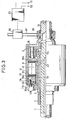
- Fig. 2 shows a second embodiment of the present invention.
- a ring body 31 which is made from bimetal or from a fluid with a high coefficient of expansion enclosed in a film of elastic material, is positioned on the inside of the sideplate 11 of the first embodiment, and the stopper ring 25 is mounted on the side of the second transmission shaft 9.
- the displacement accompanying the expansion of this ring body 31 when the temperature is elevated is used as the energizing means in the clamping of the first resistance plate 21 and the second resistance plate 23, and these resistance plates 21, 23 tightly abut to each other in a more reliable and strong manner so that the power transmission efficiency is improved.
- Fig. 3 shows a third embodiment.
- the members which are the same as those used in the first embodiment are indicated by the same reference numeral for omission of description.
- the second transmission shaft 9 is blocked at one end with referenct to the first transmission shaft 3 by a side plate 11A.
- the side plate 11A is of a L shaped in cross section.
- the outer periphery portion of the side plate 11A is engaged with the shaft end of the second transmission shaft 9 for thrust movement.
- the inner pheriphal portion is water-tightly engaged with the outer periphery of the first transmission shaft 3 through a seal mechanism 17c for rotation and thrust movement.
- the other end of the second transmission shaft 9 is water-tightly and integrally connected to a disk like member 15 at one end of the rear wheel side driving shaft 13 provided adjacent to the axis.
- the other end of the second transmission shaft 9 is also connected to the inlet shaft 1 near here through the differential gear mechanism 5.
- Another hollow shaft 41 is rotatably provided in a coaxial relationship with the first transmission shaft 3 and on the outer periphery of the first transmission shaft 3.
- the end of the hollow shaft 19 on the side of the differential gear mechanism 5 is provided with a spline 43 between the first transmission shaft 3 and the hollow shaft 41 for thrust movement.
- An annular member 29A is integrally provided on the outer periphery of the end of the hollow shaft 41.
- Mounted on the outer periphery of the other end of the hollow shaft 41 is a stopper ring 25A on one side of which an annular piston 45 is rotatably inserted.
- the piston 45 is engaged in a water tight manner on the outer periphery thereof with the inner periphery of the second transmission shaft 9 through a seal mechanism 17A for thrust movement.
- Piston 45 is also connected to the side plate 11 through a bolt means 47.
- annuler member 27 Disposed at a position inward of the piston 45 placed at one end of the interior of the operation chamber 19 is an annuler member 27 fitted into the inner periphery of the second transmission shaft 9.
- a stopper ring 19a is provided between the annular member 27 and a piston 45 to prevent the further axial movement of the annular member 39 toward the piston 45.
- the annular member 27 and the annular member 29A at one end of the hollow shaft 41 clamp the first and second resistance plates 21 and 23 in groups, thus forming a clamping means for the resistance plates 21 and 23 associated with the thrust movement of the piston 45.
- the piston 45 provides for thrust movement by the pressure variation within the operation chamber 19.
- the pressure is controlled by an outside control comprising a pressure control mechanism, which is comprised of a sensor 51, 52, a controller 53, a regulator 55 and operating fluid.
- the sensors are to detect the road conditions to which each wheel comes into contact and the differential rotations of the wheels.
- the operating fluid may be the same as the high viscous fluid with lubrication within the operating chamber 19.
- the operating fluid flows through a connduit 57, which is connected to the hollow portion of the end of the rear wheel driving shaft 13 through a connector 59, and communicated with the operation chamber 19.
- the connector 59 is the type of surrounding rotatably the rear wheel side driving shaft 13.
- the sensors 51 and 52 sense or detect the condition of road through movements of the suspension devices and the controller 53 controls the driving condition of the car.
- the controller outputs immediately orders to change the operation liquid pressure to raise the pressure by means of a regulator 55.
- the rising of pressure is transmitted from the conduit 57 to the operation chamber 19 through the connector 59.
- the piston 45 undergoes thrust movement reducing the distance between the ring members 27 and 29A which comprising a clamp device and compressing the first and second resistance plates 21 and 23 in groups arranged in a manner mentioned above.
- the resistance plates are so intimately contacted to each other as to produce or obtain the predetermined friction force.
- the car constructed according to the present invention demonstrates a suitable slippage limitation function which corresponds to condition of the rough road at the early stage of the car entering onto the rough road and also the car can enjoy considerably improved power for getting the wheels or car out of the rough road when some slippage happenes on the wheels, and improved straight-running capability or stable-running characteristic during running on a rough-road.
- the sensors 51 and 52 are changed from the detection mode of the road surface condition to the detection mode of the rotation differential between the wheels, and controlled to provide suitable slip limitation while absorbing the rotation differential between the front and rear wheels during running along a curve.
- the operation forces of the slip limitation function, operation characteristics, the operation timing with a combination of sensors 51, 52 and other adjustment and design changes can be made in a very broader diversified manner as described hereinafter, and further can be done either automatically or manually.
- the temperature of the highly viscous fluid is elevated in concert with the relative movement of the first resistance plate 21 and the second resistance plate 23 in the hermetically sealed operation chamber 19, and the pressure also increases.
- first transmission shaft 3 and the second transmission shaft 9 are joined through the thrust movement of the piston 45 and the activation of the clamp means of the two resistance plates 21, 23.
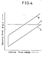
- the relationship between the strength of the joint and the temperature inside the operation chamber 19 is shown by the line A in Fig. 4.
- the clamping force can be constant from a lower internal temperature to a higher internal temperature in the operation chamber 19. This is accomplished by increasing the pressure from outside, when the temperature within the operation chamber 19 is low, and then decreasing the pressure from outside as the clamping force is increased with the increased temperature and pressure within the operation chamber 19.
- control pressure from outside can be differently set and changed to obtain arbitrary clamping charasterics, that is, slip limitation charasteristics, which is an improvement over the temperature and pressure relationship in the case where the temperature within the operation chamber 19 is not controlled from outside.
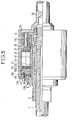
- Fig. 5 shows a fourth embodiment of the present invention.
- the same reference numbers are used for all structural parts which are substantially the same as in the first to third embodiments, and no further explanation will be made here.
- a cam mechanism 61 is positioned between the first transmission shaft 3 and the end section of the hollow shaft 41 on the side of the differential device 5 shown in the third embodiment.
- Fig. 6 shows a fifth embodiment of the present invention.
- a bimetal ring body 71 or a ring body of fluid with a high coefficient of expansion enclosed in a film of elastic material is positioned so that it contacts one surface of a ring member 29B of the hollow shaft 41 on the side of the cam mechanism 61, the one surface being opposite to the other surface of the ring member 29B which contacts the first resistance plate 21 and the second resistance plate 23, and then its outer side is in contact with the stopper ring 73.
- One end surface of the block of the first resistance plate 21 and of the block of the second resistance plate 23 directly contacts the sideplate 11.
- the clamp means of the first resistance plate 21 and the second resistance plate 23 uses the displacement of the bimetal ring body accompanying the elevation of temperature in the operation chamber 19 as activation power, which is augmented by the thrust force by means of the cam mechanism 61.
- the power transmission device of the present invention provided between the front and back wheels, or between the left and right wheels of a vehicle is suitable for effectively limiting the differential between the wheels.
Landscapes
- Engineering & Computer Science (AREA)
- General Engineering & Computer Science (AREA)
- Mechanical Engineering (AREA)
- Chemical & Material Sciences (AREA)
- Combustion & Propulsion (AREA)
- Transportation (AREA)
- Physics & Mathematics (AREA)
- Electromagnetism (AREA)
- Arrangement And Driving Of Transmission Devices (AREA)
- Retarders (AREA)
- Braking Arrangements (AREA)
Abstract
Applications Claiming Priority (2)
| Application Number | Priority Date | Filing Date | Title |
|---|---|---|---|
| JP15407/85 | 1985-01-31 | ||
| JP60015407A JPS61175340A (ja) | 1985-01-31 | 1985-01-31 | 動力伝達装置 |
Publications (3)
| Publication Number | Publication Date |
|---|---|
| EP0225389A1 true EP0225389A1 (fr) | 1987-06-16 |
| EP0225389A4 EP0225389A4 (fr) | 1988-09-07 |
| EP0225389B1 EP0225389B1 (fr) | 1990-08-16 |
Family
ID=11887875
Family Applications (1)
| Application Number | Title | Priority Date | Filing Date |
|---|---|---|---|
| EP86901125A Expired EP0225389B1 (fr) | 1985-01-31 | 1986-01-31 | Structure de transmission de puissance par un fluide visqueux |
Country Status (8)
| Country | Link |
|---|---|
| US (1) | US4771653A (fr) |
| EP (1) | EP0225389B1 (fr) |
| JP (1) | JPS61175340A (fr) |
| AU (1) | AU579712B2 (fr) |
| CA (1) | CA1268642A (fr) |
| DE (1) | DE3690052T1 (fr) |
| GB (1) | GB2181198B (fr) |
| WO (1) | WO1986004654A1 (fr) |
Cited By (4)
| Publication number | Priority date | Publication date | Assignee | Title |
|---|---|---|---|---|
| EP0379267A1 (fr) * | 1989-01-19 | 1990-07-25 | ADVANCED BRAKE & CLUTCH CO., INC. | Embrayage de friction utilisant un film hydrodynamique entre les faces de friction |
| EP0193160B1 (fr) * | 1985-02-25 | 1992-09-16 | Tochigifujisangyo Kabushikikaisha | Dispositif de transmission de puissance |
| US5207305A (en) * | 1989-01-19 | 1993-05-04 | Advanced Brake & Clutch Co., Inc. | Method and apparatus for incorporating hydrodynamic film to transfer or retard motion and dissipate heat |
| EP0321848B1 (fr) * | 1987-12-15 | 1993-11-03 | Tochigifujisangyo Kabushiki Kaisha | Appareil de transmission de puissance |
Families Citing this family (7)
| Publication number | Priority date | Publication date | Assignee | Title |
|---|---|---|---|---|
| JPH034834Y2 (fr) * | 1986-03-14 | 1991-02-07 | ||
| JP2636229B2 (ja) * | 1987-02-20 | 1997-07-30 | トヨタ自動車株式会社 | 四輪駆動用中央差動装置の差動制限機構 |
| JPS63293334A (ja) * | 1987-05-27 | 1988-11-30 | Nissan Motor Co Ltd | 四輪駆動車用トランスファ装置 |
| AT396812B (de) * | 1988-07-08 | 1993-12-27 | Viscodrive Gmbh | Viskosekupplung |
| JPH06100248B2 (ja) * | 1988-10-28 | 1994-12-12 | ビスコドライブジャパン株式会社 | 差動制限機構付差動装置 |
| JPH0565947A (ja) * | 1991-09-05 | 1993-03-19 | Soken:Kk | 回転運動を往復運動に変える方法及びその装置 |
| CN112141916B (zh) * | 2020-11-26 | 2021-02-23 | 万鑫精工(湖南)股份有限公司 | 起重机的回转减速设备 |
Family Cites Families (19)
| Publication number | Priority date | Publication date | Assignee | Title |
|---|---|---|---|---|
| US3292720A (en) * | 1964-05-28 | 1966-12-20 | Deere & Co | Control means for locking differential |
| US3323389A (en) * | 1964-11-30 | 1967-06-06 | Gen Motors Corp | Live axle |
| GB1357106A (en) * | 1970-07-18 | 1974-06-19 | Ferguson Ltd Harry | Rotary couplings |
| US3760922A (en) * | 1970-07-18 | 1973-09-25 | Ferguson Ltd H | Rotary couplings |
| GB1411283A (en) * | 1972-06-21 | 1975-10-22 | Gkn Transmissions Ltd | Four-wheel-drive vehicles |
| US3800930A (en) * | 1972-09-22 | 1974-04-02 | Sommer Co | Variable speed drive |
| GB1475141A (en) * | 1974-05-09 | 1977-06-01 | Gkn Transmissions Ltd | Control couplings |
| GB1509374A (en) * | 1974-05-28 | 1978-05-04 | Gkn Transmissions Ltd | Control couplings |
| US4031780A (en) * | 1974-11-29 | 1977-06-28 | Chrysler Corporation | Coupling apparatus for full time four wheel drive |
| GB1498061A (en) * | 1975-02-25 | 1978-01-18 | Gkn Transmissions Ltd | Control couplings and gearing combined therewith |
| GB1551009A (en) * | 1975-07-10 | 1979-08-22 | Gkn Transmissions Ltd | Control couplings |
| US4040271A (en) * | 1975-10-22 | 1977-08-09 | Harry Ferguson Limited | Viscous shear couplings |
| US4058027A (en) * | 1976-07-09 | 1977-11-15 | Gkn Transmissions Limited | Control couplings |
| DE2636741A1 (de) * | 1976-08-14 | 1978-02-16 | Hurth Masch Zahnrad Carl | Reibungskupplung |
| DE3269958D1 (en) * | 1981-06-26 | 1986-04-24 | Ferguson Ltd Harry | Differential drive arrangement |
| US4444298A (en) * | 1981-07-10 | 1984-04-24 | The Secretary Of State For Defence In Her Britannic Majesty's Government Of The United Kingdom Of Great Britain And Northern Ireland | Viscous shear clutch |
| US4559847A (en) * | 1983-06-13 | 1985-12-24 | Deere & Company | Steering pressure-responsive differential lock control system |
| DE3408977A1 (de) * | 1984-03-12 | 1985-09-12 | Bayerische Motoren Werke AG, 8000 München | Fluessigkeitsreibungskupplung, insbesondere fuer ausgleichsgetriebe von kraftfahrzeugen |
| DE3440492A1 (de) * | 1984-11-06 | 1986-05-07 | Xaver Fendt & Co, 8952 Marktoberdorf | Verfahren und einrichtung zum automatischen vermindern des relativschlupfes eines achswellenpaares eines kraftfahrzeuges |
-
1985
- 1985-01-31 JP JP60015407A patent/JPS61175340A/ja active Pending
-
1986
- 1986-01-30 CA CA000500733A patent/CA1268642A/fr not_active Expired
- 1986-01-31 EP EP86901125A patent/EP0225389B1/fr not_active Expired
- 1986-01-31 DE DE19863690052 patent/DE3690052T1/de not_active Withdrawn
- 1986-01-31 AU AU53953/86A patent/AU579712B2/en not_active Ceased
- 1986-01-31 US US06/923,833 patent/US4771653A/en not_active Expired - Fee Related
- 1986-01-31 WO PCT/JP1986/000038 patent/WO1986004654A1/fr not_active Ceased
- 1986-01-31 GB GB8623502A patent/GB2181198B/en not_active Expired
Cited By (4)
| Publication number | Priority date | Publication date | Assignee | Title |
|---|---|---|---|---|
| EP0193160B1 (fr) * | 1985-02-25 | 1992-09-16 | Tochigifujisangyo Kabushikikaisha | Dispositif de transmission de puissance |
| EP0321848B1 (fr) * | 1987-12-15 | 1993-11-03 | Tochigifujisangyo Kabushiki Kaisha | Appareil de transmission de puissance |
| EP0379267A1 (fr) * | 1989-01-19 | 1990-07-25 | ADVANCED BRAKE & CLUTCH CO., INC. | Embrayage de friction utilisant un film hydrodynamique entre les faces de friction |
| US5207305A (en) * | 1989-01-19 | 1993-05-04 | Advanced Brake & Clutch Co., Inc. | Method and apparatus for incorporating hydrodynamic film to transfer or retard motion and dissipate heat |
Also Published As
| Publication number | Publication date |
|---|---|
| EP0225389B1 (fr) | 1990-08-16 |
| AU579712B2 (en) | 1988-12-08 |
| JPS61175340A (ja) | 1986-08-07 |
| WO1986004654A1 (fr) | 1986-08-14 |
| GB2181198B (en) | 1989-11-22 |
| GB8623502D0 (en) | 1986-11-05 |
| DE3690052T1 (fr) | 1987-04-23 |
| US4771653A (en) | 1988-09-20 |
| EP0225389A4 (fr) | 1988-09-07 |
| GB2181198A (en) | 1987-04-15 |
| AU5395386A (en) | 1986-08-26 |
| CA1268642A (fr) | 1990-05-08 |
Similar Documents
| Publication | Publication Date | Title |
|---|---|---|
| US7806797B2 (en) | Ball ramp assembly with variable pitch of the ball grooves | |
| US5556343A (en) | Method and device for controlling a coupling | |
| US5197583A (en) | Torque transmission device | |
| US5690201A (en) | Method and device for controlling a coupling | |
| US4513633A (en) | Positive drive and generated cam surfaces therefor | |
| US4690258A (en) | Hydraulic power transmission device with centrifugally actuated clutch override | |
| EP0225389B1 (fr) | Structure de transmission de puissance par un fluide visqueux | |
| US6182808B1 (en) | Viscous actuated ball ramp clutch having through shaft capability | |
| CA1257106A (fr) | Dispositif de transmisson d'energie mecanique | |
| EP0314420A1 (fr) | Unité d'embrayage à frottement visqueux pour transmission de couple dans une automobile | |
| GB2377260A (en) | A torque split power transmission | |
| EP0145462B1 (fr) | Transmission à rainures pour variateur à courroie métallique | |
| EP3486517B1 (fr) | Dispositif de transmission de couple, appareil de freinage et appareil de transmission d'énergie | |
| US6102178A (en) | Viscous actuated ball ramp clutch | |
| US5967276A (en) | Viscous actuated ball ramp clutch and improved housing therefor | |
| US5101678A (en) | Coupling device for power transfer | |
| US6237735B1 (en) | Viscous actuated ball ramp clutch having one-way clutch | |
| EP0009343B1 (fr) | Transmission à variation de vitesse continue | |
| EP0279127B1 (fr) | Joint universel télescopique à tripode | |
| EP0881406B1 (fr) | Embrayage à billes et rampes actionné par fluide visqueux | |
| KR940008829B1 (ko) | 차동기어장치 | |
| KR0136892B1 (ko) | 커플링을 제어하는 방법 및 장치(Method and Device for Controlling a Coupling) | |
| US4983150A (en) | Differential gear apparatus with differential limitation mechanism | |
| JPH02120527A (ja) | トルク伝達継手 | |
| JP2992109B2 (ja) | 回転力切換え装置 |
Legal Events
| Date | Code | Title | Description |
|---|---|---|---|
| PUAI | Public reference made under article 153(3) epc to a published international application that has entered the european phase |
Free format text: ORIGINAL CODE: 0009012 |
|
| 17P | Request for examination filed |
Effective date: 19860923 |
|
| AK | Designated contracting states |
Kind code of ref document: A1 Designated state(s): FR |
|
| A4 | Supplementary search report drawn up and despatched |
Effective date: 19880907 |
|
| 17Q | First examination report despatched |
Effective date: 19881021 |
|
| GRAA | (expected) grant |
Free format text: ORIGINAL CODE: 0009210 |
|
| AK | Designated contracting states |
Kind code of ref document: B1 Designated state(s): FR |
|
| ET | Fr: translation filed | ||
| PLBE | No opposition filed within time limit |
Free format text: ORIGINAL CODE: 0009261 |
|
| STAA | Information on the status of an ep patent application or granted ep patent |
Free format text: STATUS: NO OPPOSITION FILED WITHIN TIME LIMIT |
|
| 26N | No opposition filed | ||
| PGFP | Annual fee paid to national office [announced via postgrant information from national office to epo] |
Ref country code: FR Payment date: 19981223 Year of fee payment: 14 |
|
| PG25 | Lapsed in a contracting state [announced via postgrant information from national office to epo] |
Ref country code: FR Free format text: LAPSE BECAUSE OF NON-PAYMENT OF DUE FEES Effective date: 20000929 |
|
| REG | Reference to a national code |
Ref country code: FR Ref legal event code: ST |