EP3486517B1 - Dispositif de transmission de couple, appareil de freinage et appareil de transmission d'énergie - Google Patents
Dispositif de transmission de couple, appareil de freinage et appareil de transmission d'énergie Download PDFInfo
- Publication number
- EP3486517B1 EP3486517B1 EP16908866.3A EP16908866A EP3486517B1 EP 3486517 B1 EP3486517 B1 EP 3486517B1 EP 16908866 A EP16908866 A EP 16908866A EP 3486517 B1 EP3486517 B1 EP 3486517B1
- Authority
- EP
- European Patent Office
- Prior art keywords
- shaft
- plates
- torque
- plate
- transmission apparatus
- Prior art date
- Legal status (The legal status is an assumption and is not a legal conclusion. Google has not performed a legal analysis and makes no representation as to the accuracy of the status listed.)
- Not-in-force
Links
- 230000005540 biological transmission Effects 0.000 title claims description 154
- 239000012530 fluid Substances 0.000 claims description 70
- 238000010008 shearing Methods 0.000 claims description 65
- 230000007704 transition Effects 0.000 description 38
- 230000033001 locomotion Effects 0.000 description 33
- 230000007423 decrease Effects 0.000 description 20
- 230000008878 coupling Effects 0.000 description 16
- 238000010168 coupling process Methods 0.000 description 16
- 238000005859 coupling reaction Methods 0.000 description 16
- 239000003921 oil Substances 0.000 description 11
- 230000008859 change Effects 0.000 description 9
- 239000007788 liquid Substances 0.000 description 9
- 238000006073 displacement reaction Methods 0.000 description 8
- 238000010586 diagram Methods 0.000 description 6
- 230000000694 effects Effects 0.000 description 5
- XUIMIQQOPSSXEZ-UHFFFAOYSA-N Silicon Chemical compound [Si] XUIMIQQOPSSXEZ-UHFFFAOYSA-N 0.000 description 4
- 230000001133 acceleration Effects 0.000 description 4
- 238000006243 chemical reaction Methods 0.000 description 4
- 230000012447 hatching Effects 0.000 description 4
- 229910052710 silicon Inorganic materials 0.000 description 4
- 239000010703 silicon Substances 0.000 description 4
- 238000003780 insertion Methods 0.000 description 3
- 230000037431 insertion Effects 0.000 description 3
- 239000000314 lubricant Substances 0.000 description 3
- 230000009471 action Effects 0.000 description 2
- 230000008901 benefit Effects 0.000 description 2
- 230000003247 decreasing effect Effects 0.000 description 2
- 238000013461 design Methods 0.000 description 2
- 238000005461 lubrication Methods 0.000 description 2
- 238000005259 measurement Methods 0.000 description 2
- 230000007246 mechanism Effects 0.000 description 2
- 238000000034 method Methods 0.000 description 2
- 239000002245 particle Substances 0.000 description 2
- 238000007789 sealing Methods 0.000 description 2
- 239000011800 void material Substances 0.000 description 2
- 238000005299 abrasion Methods 0.000 description 1
- 230000002411 adverse Effects 0.000 description 1
- 230000002457 bidirectional effect Effects 0.000 description 1
- 230000008602 contraction Effects 0.000 description 1
- 230000007613 environmental effect Effects 0.000 description 1
- 238000009434 installation Methods 0.000 description 1
- 230000001050 lubricating effect Effects 0.000 description 1
- 238000004519 manufacturing process Methods 0.000 description 1
- 239000002480 mineral oil Substances 0.000 description 1
- 235000010446 mineral oil Nutrition 0.000 description 1
- 230000000704 physical effect Effects 0.000 description 1
- 230000002265 prevention Effects 0.000 description 1
- 230000009467 reduction Effects 0.000 description 1
- 230000004044 response Effects 0.000 description 1
- 230000004043 responsiveness Effects 0.000 description 1
- 238000012546 transfer Methods 0.000 description 1
Images


Classifications
-
- F—MECHANICAL ENGINEERING; LIGHTING; HEATING; WEAPONS; BLASTING
- F16—ENGINEERING ELEMENTS AND UNITS; GENERAL MEASURES FOR PRODUCING AND MAINTAINING EFFECTIVE FUNCTIONING OF MACHINES OR INSTALLATIONS; THERMAL INSULATION IN GENERAL
- F16D—COUPLINGS FOR TRANSMITTING ROTATION; CLUTCHES; BRAKES
- F16D57/00—Liquid-resistance brakes; Brakes using the internal friction of fluids or fluid-like media, e.g. powders
- F16D57/007—Liquid-resistance brakes; Brakes using the internal friction of fluids or fluid-like media, e.g. powders with variable brake geometry, e.g. axially movable rotor or stator
-
- F—MECHANICAL ENGINEERING; LIGHTING; HEATING; WEAPONS; BLASTING
- F16—ENGINEERING ELEMENTS AND UNITS; GENERAL MEASURES FOR PRODUCING AND MAINTAINING EFFECTIVE FUNCTIONING OF MACHINES OR INSTALLATIONS; THERMAL INSULATION IN GENERAL
- F16D—COUPLINGS FOR TRANSMITTING ROTATION; CLUTCHES; BRAKES
- F16D35/00—Fluid clutches in which the clutching is predominantly obtained by fluid adhesion
- F16D35/005—Fluid clutches in which the clutching is predominantly obtained by fluid adhesion with multiple lamellae
-
- F—MECHANICAL ENGINEERING; LIGHTING; HEATING; WEAPONS; BLASTING
- F16—ENGINEERING ELEMENTS AND UNITS; GENERAL MEASURES FOR PRODUCING AND MAINTAINING EFFECTIVE FUNCTIONING OF MACHINES OR INSTALLATIONS; THERMAL INSULATION IN GENERAL
- F16D—COUPLINGS FOR TRANSMITTING ROTATION; CLUTCHES; BRAKES
- F16D59/00—Self-acting brakes, e.g. coming into operation at a predetermined speed
-
- F—MECHANICAL ENGINEERING; LIGHTING; HEATING; WEAPONS; BLASTING
- F16—ENGINEERING ELEMENTS AND UNITS; GENERAL MEASURES FOR PRODUCING AND MAINTAINING EFFECTIVE FUNCTIONING OF MACHINES OR INSTALLATIONS; THERMAL INSULATION IN GENERAL
- F16D—COUPLINGS FOR TRANSMITTING ROTATION; CLUTCHES; BRAKES
- F16D2127/00—Auxiliary mechanisms
- F16D2127/001—Auxiliary mechanisms for automatic or self-acting brake operation
- F16D2127/002—Auxiliary mechanisms for automatic or self-acting brake operation speed-responsive
Definitions
- the present invention relates to a torque transmission apparatus that generates, using the shearing force of a viscous fluid, torque corresponding to the speed of relative rotation between two shafts (hereinafter referred to as "relative rotational speed") so as to reduce the relative rotational speed, and also relates to a braking apparatus and a power transmission apparatus that include the torque transmission apparatus.
- a torque transmission apparatus is conventionally known that generates torque corresponding to the relative rotational speed between two shafts by using the shearing force of a viscous fluid. Also, a power transmission apparatus and a braking apparatus that include such a fluid-type torque transmission apparatus are also known.
- An example of a power transmission apparatus that includes a fluid-type torque transmission apparatus is a viscous coupling for distributing driving power to main driving wheels (front wheels) and auxiliary driving wheels (rear wheels) in a part-time four-wheel-drive vehicle (see JP H09-058287 A ).
- the transmission torque transmitted to the auxiliary driving wheels is preferably small when the relative rotational speed is small (hereinafter, referred to as "low differential motion range").
- low differential motion range the transmission torque transmitted to the auxiliary driving wheels
- high differential motion range the transmission torque transmitted to the auxiliary driving wheels needs to be large when the relative rotational speed is large (hereinafter, referred to as "high differential motion range").
- JP H09-058287 A discloses a power transmission apparatus that includes both a viscous coupling and a dilatant fluid coupling.
- Dilatant fluids have properties where the shear resistance increases rapidly when the shear rate exceeds a certain value.
- a dilatant fluid in parallel with a viscous coupling it is possible to achieve a transmission torque that is large in the high differential motion range while it is sufficiently small in the low differential motion range.
- JP 2013-148183 A discloses a braking apparatus including a fluid-type torque transmission apparatus.
- the braking apparatus disclosed in this document is intended for use in a walking rollator or the like, and is desirably configured such that a brake is applied as lightly as possible during travel at low speeds, and is firmly applied during travel at high speeds for hazard prevention. Accordingly, as with the power transmission apparatus described above, the braking apparatus is required to provide a transmission torque that is large in the high differential motion range while being small in the low differential motion range.
- an inner rotor is surrounded by an outer rotor with a first space interposed therebetween, and the outer rotor is further sealed and surrounded by a drum via a liquid fluid contained in a second space.
- JP 2013-148183 A is configured such that the power is reliably transmitted from the outer rotor to the drum by enclosing the dilatant fluid in the second space and increasing the viscosity of the dilatant fluid, along with an increase in the shear rate produced between the drum and the outer rotor when the centrifugal force of the inner rotor causes the projecting/retracting member to advance and the outer rotor and the inner rotor to integrally rotate.
- the interaxle differential comprises a liquid friction coupling and a planetary gear train comprising three torque-transmitting members.
- the liquid friction coupling comprises a liquid-filled housing, a coupling shaft, which coaxially protrudes into said housing at least one set of radially inwardly extending, axially spaced apart outer blades, which are mounted on the housing, and radially outwardly extending, axially spaced apart inner blades, which are fixed to the shaft in said housing and axially staggered from the outer blades.
- Each of said outer blades is adjustable in a radial plane to vary the radial overlap between the outer and inner blades.
- a first of said torque-transmitting members of the planetary gear train is directly connected to an input member of the differential gear.
- a second of said torque-transmitting members is connected to said coupling shaft. Only a third of said torque-transmitting members is connected in said differential to an output member of the differential. The housing of the liquid friction coupling is held against rotation.
- DE 26 36 741 A1 discloses a friction clutch having a pair of axially spaced first friction members connected to a first clutch half and at least one second friction member connected to the other clutch half. Both of the clutch halves define a housing for containing a liquid which is free to flow between the first friction members as well as between the second friction member and the first friction members when the second friction member is interposed between the first friction members.
- the second friction member is supported for movement into and out of axial alignment with the first friction members so that the liquid contained between the first and second friction members will function as the torque transmitting medium to effect a drive from the first clutch half to the second clutch half and vice versa.
- JP 2013-148183 A that uses the viscosity of the fluid between the outer rotor and the drum by engaging the projecting/retracting member that has advanced from the inner rotor due to a centrifugal force with the outer rotor and integrally rotating the projecting/retracting member and the outer rotor, if the rotation speed of the inner rotor is slow, the centrifugal force is small, and it is therefore not possible to cause the projecting/retracting member to advance. Accordingly, it is difficult to operate the braking apparatus at a relatively low rotation speed.
- the present invention has been made in view of the problems described above, and it is an object of the present invention to implement a torque transmission apparatus that has desired transmission characteristics by using an ordinary viscous fluid without using a dilatant fluid that is difficult to handle.
- a torque transmission apparatus is provided as set forth in claim 1.
- a pair of the movable plates are provided so as to have rotational symmetry with respect to the rotational axis of the shaft, or a pair of the movable plates are provided so as to have plane symmetry with respect to a plane including the rotational axis of the shaft.
- the present invention encompasses a braking apparatus and a power transmission apparatus that include any of the torque transmission apparatuses described above.
- the present invention it is possible to implement a torque transmission apparatus that has the characteristics that a sufficiently small transmission torque is obtained in the low differential motion range, and a large transmission torque is obtained in the high differential motion range, by using an ordinary fluid such as a silicon oil without using a dilatant fluid that is difficult to handle.
- the torque transmission apparatus has the characteristics that a change in the transmission torque caused by the relative rotational speed is amplified, and thus a braking apparatus or a power transmission apparatus that requires such characteristics can be implemented with a simple configuration using a widely used viscous fluid.
- a torque transmission apparatus includes a case member that forms an operation chamber that contains a viscous fluid, and a shaft and a plurality of outer plates and inner plates that are housed in the case member.
- a case member that forms an operation chamber that contains a viscous fluid
- second plates an assembly of a plurality of inner plates (second plates) will be referred to as a "second plate member”.
- a first plate member including a plurality of outer plates that are provided at a predetermined pitch is connected to the case member.
- a second plate member including a plurality of inner plates that are provided at the same pitch as that of the outer plates is connected to the shaft.
- the configuration described above is the same as that of a conventional torque transmission apparatus.
- the shearing force taken on by both plates also increases due to the increase in the shear rate of the viscous fluid.
- this configuration it is not possible to significantly change the transmission torque to a level that exceeds the viscosity characteristics of the viscous fluid.
- either the inner plates or the outer plates are configured to be movable so as to change the area where both plates are subjected to the shearing force from the viscous fluid, and thus the transmission torque is changed significantly to a level that exceeds the viscosity characteristics of the viscous fluid.
- the change in the shearing force taken on by the plates is increased by displacing either the inner plates or the outer plates that are configured to be movable in a plane direction so as to change the overlapping area (the area of opposing faces with a gap interposed therebetween (hereinafter referred to as "interlocking area")) between the movable plates and the plates that remain fixed to the case member or the shaft.
- interlocking area the area of opposing faces with a gap interposed therebetween
- the movable plates are biased by an elastic member to a first position at which the interlocking area is small, and thus a small transmission torque can be maintained unless a force that displaces the movable plates to a second position at which the interlocking area is large is generated against a biasing force applied by the elastic member.
- the shearing force generated by relative rotation acts in a direction to bias the movable plates to the second position. Even when the movable plates are held at the first position, the shearing force increases according to the viscosity characteristics of the viscous fluid with the increase in the relative rotational speed.
- the interlocking area is large, and it is therefore possible to achieve a large transmission torque surpassing the effect produced simply by the shear rate of the fluid increasing at the first position.
- the shearing force also decreases, as a result of which the movable plates return to the first position due to the biasing force of the elastic member.
- the torque transmission apparatus has the characteristics that a change in the transmission torque caused by the relative rotational speed is amplified, and thus a braking apparatus or a power transmission apparatus that requires such characteristics can be implemented with a simple configuration using a widely used viscous fluid.
- FIG. 1 is a front view of a torque transmission apparatus according to a first embodiment of the present invention when viewed from a direction of the axis of a shaft 3 (hereinafter referred to as "axial direction")
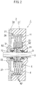
- FIG. 2 is a cross-sectional view taken along the line A-A shown in FIG. 1 .
- FIG. 1 shows a state in which a cap 22, an O-ring 23, a bush 72, and an oil seal 82 shown in FIG. 2 are removed.
- a torque transmission apparatus 1 includes a case member 2, a shaft 3, a first plate member 4, a second plate member 5, and a tension coil spring 6, and further includes bushes 71 and 72 that are bearings, and oil seals 81 and 82 that are sealing members. Also, in the present embodiment, the inner plates that constitute the second plate member 5 are movable plates.
- the bottomed cylindrical case member 2 is composed of a case 21 that has a cylindrical shape and a bottom surface, and a disk-shaped cap 22 that closes an open face of the case 21, and includes an operation chamber 20 that is an internal space.
- the operation chamber 20 the first plate member 4 that is connected to the case member 2 and the second plate member 5 that rotates integrally with the shaft 3 are housed, and a viscous fluid is contained in the void of the operation chamber 20.
- the shaft 3 is inserted through and supported by a hole formed at the center of the bottom surface of the case 21 and a hole formed at the center of the cap 22 via the bushes 71 and 72 so as to be capable of rotating relative to the case member 2.
- Torque transmission occurs between the shaft 3 and the case member 2 that rotate relative to each other via the viscous fluid contained in the operation chamber 20. Specifically, each outer plate 41 of the first plate member 4 that is connected to the case member 2 and each inner plate 51 of the second plate member 5 that is connected to the shaft 3 are interlocked with a gap, and the gap is filled with the viscous fluid.
- a counteracting shearing force is generated between both plates through relative rotation, and torque corresponding to the viscosity of the fluid and the relative rotational speed is generated between two shafts that are the shaft 3 and the case member 2, and thus the torque can be transmitted.
- the torque transmission apparatus 1 according to the present embodiment does not use centrifugal force, and thus the driving side may be the shaft 3 or may be the case member 2.
- the torque transmission apparatus 1 may be configured such that the case member 2 is fixed to the vehicle body, and wheels are fixed to the shaft 3.
- a configuration is also possible in which the shaft 3 is fixed to the vehicle body and the case member 2 is used as a part of a wheel.
- the first plate member 4 On the inner surface side of the cylindrical wall of the case 21, a plurality of doughnut-like disk-shaped outer plates 41 are provided at a predetermined pitch in the axial direction, each outer plate 41 having an outer shape and a hole that are concentric about a point on the axis of the shaft 3.
- the first plate member 4 is composed of four outer plates 41, but the number of outer plates can be changed as appropriate according to the required torque characteristics, together with the number of inner plates that constitute the second plate member 5, which will be described later.
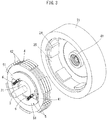
- FIG. 3 is a perspective view of the first plate member 4 and the second plate member 5 removed from the case 21.
- the outer edge portion of each of the outer plates 41 that constitute the first plate member 4 includes, around the entire circumference thereof, plate fixing projections 42 that protrude radially from the outer edge.
- plate fixing projections 42 that protrude radially from the outer edge.
- protrusion portions 24 and recess portions 25 are alternately provided on the inner surface of the cylindrical wall of the case 21, protrusion portions 24 and recess portions 25 are alternately provided.
- the diameter of the protrusion portions 24 substantially matches the diameter of the outer edge of the outer plates 41
- the diameter of the recess portions 25 substantially matches the diameter of the outer edge of the plate fixing projections 42
- the circumferential length of the recess portions 25 substantially matches the circumferential length of the plate fixing projections 42. Accordingly, the first plate member 4 including the plate fixing projections 42 can be fit inserted to the case 21 including the protrusion portions 24 and the recess portions 25 so as to be incapable of rotating relative to the case 21.
- the first plate member 4 is integrally connected to the case 21. Accordingly, rotation with the second plate member 5 does not occur when the case 21 and the shaft 3 rotate relative to each other, and thus the torque generated by the shearing force received from the viscous fluid can be transmitted to the case member 2.
- the plate fixing projections 42 have a dimension in the thickness direction larger than the thickness of the outer plates 41.
- the four outer plates 41 abut against each other at their plate fixing projections 42, and are sandwiched between the bottom surface of the case 21 and a positioning projection 26 provided on the cap 22. Accordingly, the outer plates 41 can be positioned at a predetermined interval by adjusting the thickness of the plate fixing projections 42.
- the pitch of the four outer plates 41 is the sum of the thickness of an outer plate 41, the thickness of an inner plate 51 that is interlocked with the outer plate 41, and the thickness of two gaps that are filled with the viscous fluid that generates shear resistance between both plates.
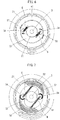
- FIG. 4 is a perspective view of the second plate members 5 in the normal mode.
- FIG. 5 is a perspective view of the second plate members 5 in the high torque mode. In the diagrams, for the sake of visibility, the upper second plate member 5 is indicated by an imaginary line.
- the shaft 3 is inserted through a shaft insertion hole formed at the center of a hub 31.
- the hub 31 is fixed to the shaft 3 by press fitting a hub fixing pin 32 that passes from the center in the axis direction of a cylindrical side surface of the hub 31, through the axis of the shaft 3, and to the other side of the cylindrical side surface of the hub 31.
- a pair of arms 33 for supporting swing shafts 34 are provided at two locations (the positions rotated 180 degrees about the axis of the shaft 3) on the cylindrical side surface of the hub 31.
- a swing shaft support hole is formed in parallel to the axis of the shaft 3 at a position at a predetermined distance from the axis of the shaft 3, and a swing shaft 34 is fixedly inserted through the swing shaft support hole.
- each second plate member 5 has a substantially semicircular shape when viewed from the axial direction, and each inner plate 51 includes, at one end portion thereof, a hole through which the swing shaft 34 is inserted.
- the second plate member 5 is supported on the hub 31 so as to be capable of swinging within a plane perpendicular to the shaft 3.
- a plurality of inner plates 51 that constitute the second plate member 5 are provided at a predetermined pitch in the axial direction.
- two second plate members 5 are disposed to have rotational symmetry with respect to the axis of the shaft 3, each second plate member 5 including five inner plates 51 that are integrally connected by a connecting member 52 on the inner side.
- the connecting member 52 also functions as a stopper that limits the range of movement of the second plate member 5 on the second position side. Specifically, when the interlocking area between the first plate member 4 and the second plate member 5 increases in the high torque mode, the leading end of each inner plate 51 is interposed, in a gap, between two adjacent outer plates 41, but when the leading ends of the outer plates 41 abut against the connecting member 52, the second plate member 5 cannot be displaced beyond this position. Accordingly, in the high torque mode, relative rotation is performed while the leading ends of the outer plates 41 and the connecting member 52 slide against each other.
- a stopper for delimiting the swing angle may also be additionally provided between the second plate member 5 and the hub 31. In this case, it is possible to prevent wear while avoiding sliding between the first plate member 4 and the second plate member 5.
- the diameter of the substantially semicircular inner curved surface of the inner plates 51 substantially matches the diameter of the cylindrical side surface of the hub 31, and as shown in FIG. 4 , in the normal mode, the inner plates 51 are disposed so as to cover the cylindrical side surface of the hub 31 counterclockwise from their end portion that is supported on the hub 31 by the swing shaft 34 toward the other swing shaft.
- a hook 53 is provided near the leading end of the second plate member 5, and a tension coil spring 6 that is an elastic member is provided between the hook 53 and the other swing shaft 34, and the second plate member 5 is biased in the direction of the axis of the shaft 3. Accordingly, in the normal mode, a state is kept in which the inner curved surface of the inner plates 51 abut against the cylindrical side surface of the hub 31.
- a tension coil spring is used as an elastic member, but the elastic member is not limited thereto as long as it is possible to bias the second plate member 5 in the direction of the axis of the shaft 3.
- a torsion spring may be used to generate a biasing force between the second plate member 5 and the hub 31 about the swing shaft 34.
- each inner plate 51 in the normal mode, is on a circle centered on the axis of the shaft 3 when viewed from the axial direction. That is, the outer curved surface of each inner plate 51, excluding the leading end portion, has an arc shape that is concentric with the inner curved surface. Accordingly, in the normal mode in which the inner curved surface abuts against the cylindrical side surface of the hub 31 that has the same diameter, the center of the arc of the outer curved surface is positioned on the axis of the shaft 3. Thus, in the normal mode, the outer curved surface of each inner plate 51, excluding the leading end portion, has a perfect circular shape centered on the axis of the shaft 3 when viewed from the axial direction.
- each inner plate 51 is smaller than the diameter of the inner curved surface of the outer plate 41, and thus each of the inner plates 51, excluding the leading end portion, do not interlock with the outer plates 41, and thus the shearing force of the fluid is small. Accordingly, the transmission torque in the normal mode can be reduced.
- each inner plate 51 has a shape that protrudes radially from the remaining portion, and thus interlocks with the outer plate 41 even in the normal mode. Accordingly, the leading end portion of the inner plate 51 interlocked with the outer plate 41 is subjected to the shearing force of the fluid due to differential motion, which causes a moment about the swing shaft 34 and biases the inner plate 51 radially outward (in a direction in which the interlocking area increases).
- the distance between the line of action of the shearing force and the swing shaft 34 can be increased, and thus a moment that displaces the second plate member 5 in a direction to increase the interlocking area about the swing shaft 34 is likely to be generated. Also, a portion of the inner plate 51 other than the leading end portion does not interlock with the outer plate 41, and thus a shearing force is unlikely to be generated, and the transmission torque can be minimized.
- a braking apparatus including the torque transmission apparatus configured as described above in a walking rollator, a wheelchair or the like, the load during normal travel can be reduced, and a brake can be reliably applied when an excessive speed is reached.
- the portion of the second plate member (inner plate 51) other than the leading end portion may be interlocked with the outer plate 41.
- the torque transmission apparatus can be used in a power transmission apparatus that requires a certain degree of transmission torque even in the normal mode.
- transition between the normal mode and the high torque mode is made possible by swinging the movable plates about the swing shaft, and thus the location where sliding resistance occurs on the movable plates during transition between modes can be limited to the vicinity of the swing shaft.
- the present embodiment is configured such that the shearing force generates a moment that swingably moves the movable plates to the second position, and thus the moment of the sliding resistance can be reduced with respect to the moment generated by the shearing force, and a stable transition between modes can be achieved.
- the inner plates 51 are configured as movable plates. Accordingly, the interlocking position where both plates are interlocked in the high torque mode can be set to a position distant from the shaft rotational axis. At the position distant from the shaft, the relative speed between two plates is high, and thus the shearing force is large. Also, because torque is equal to the product of force and distance, the transmission torque increases as the distance of the location where a shearing force occurs from the rotational axis increases. Accordingly, the torque transmission apparatus according to the present embodiment can provide a large transmission torque in the high torque mode while having a compact size.
- two second plate members 5 are provided so as to have 180 degree rotational symmetry about the axis.
- three second plate members 5 may be provided so as to have 120 degree rotational symmetry.
- four or more second plate members 5 may be provided.
- only one second plate member 5 may be provided by removing one second plate member 5 from the configuration of the present embodiment. Even with this configuration, the advantageous effects of the present invention can be obtained.
- the torque transmission apparatus 1 is used by filling the operation chamber 20 with a viscous fluid. Accordingly, in order to prevent the leakage of the fluid, as shown in FIG. 2 , an O-ring 23 is placed on the joint face between the case 21 and the cap 22, and oil seals 81 and 82 are placed between the cap 22 and the shaft 3 and between the case 21 and the shaft 3, respectively.
- the case 21 and the cap 22 can be joined using a known fastening means such as a bolt.
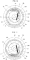
- FIGS. 6 and 7 are diagrams of the torque transmission apparatus 1 in the normal mode and the high torque mode when viewed from the axial direction, respectively. As in FIG. 1 , these diagrams show a state in which the cap 22, the O-ring 23, the bush 72, and the oil seal 82 are removed.
- FIG. 8 is a graph showing measured values of torque transmitted from the shaft 3 to the case member 2 when the relative rotational speed is changed in the torque transmission apparatus 1 according to the present embodiment shown in FIGS. 1 and 2 .
- a torque transmission apparatus 1 whose operation chamber with an inner diameter of 71.2 mm and a dimension in the axial direction of 20 mm was filled with a silicon oil (product number: KF96-10000CS) available from Shin-Etsu Chemical Co., Ltd. was used. Then, a motor connected to the case member 2 was rotated with the shaft 3 being fixed, and torque was measured using a torque sensor attached to the shaft 3.
- a silicon oil product number: KF96-10000CS
- the relative rotational speed was increased from a stopped state to 105 rpm at a rate of acceleration of 2.5 rpm per second, and thereafter decreased to the stopped state at a rate of acceleration of -2.5 rpm.
- the thick line indicates relative rotational speed in relation to transmission torque characteristics during acceleration
- the thin line indicates relative rotational speed versus transmission torque characteristics during deceleration.
- the inner plate 51 is biased in the direction of the axis of the shaft 3 by the tension coil spring 6. With the biasing force of the tension coil spring 6, a counterclockwise moment about the swing shaft 34 acts on the inner plate 51.
- the transmission torque at this time is about 0.1 Nm.
- interlocking areas S2 (indicated by hatching) are large, and thus a large shearing force acts on the outer plates 41 and the inner plates 51. Accordingly, the transmission torque produced between the case member 2 and the shaft 3 takes a large value surpassing the amount of increase in transmission torque caused by simply increasing the shear rate of the fluid.
- the transmission torque changed rapidly from about 0.2 Nm to about 1.5 Nm according to the outward displacement of the inner plates 51. After that, the operation transitioned to the high torque mode, and the transmission torque increased as the relative rotational speed increased. Ultimately, the transmission torque reached about 2.7 Nm.
- the inner plates 51 are at the second position at the start of deceleration, and thus the shearing force is large, and the inner plates 51 are held at the second position even at a lower speed than the relative rotational speed at which the transmission torque changes rapidly during acceleration.
- the shearing force decreases, and the biasing force applied by the elastic member dominates. Accordingly, the inner plates 51 are returned to the first position by the time the relative rotational speed reaches 0, and the mode transitions to the normal mode.
- the torque transmission apparatus 1 is suitable for use as a braking apparatus for a walking rollator or the like.
- two second plate members 5 are provided at positions that have 180 degree rotational symmetry about the axis of the shaft 3, and each plate member 5 can transition to the high torque mode when the case member 2 makes a clockwise differential motion (forward rotation) with respect to the shaft 3.
- the torque transmission apparatus 1 is used as, for example, a viscous coupling for distributing driving power to main driving wheels (front wheels) and auxiliary driving wheels (rear wheels) in a part-time four-wheel-drive vehicle, it is possible to prevent the power transmission apparatus from being damaged even when a rear wheel-side propeller shaft rotates at a high speed, without using a one-way clutch in combination.
- a torque transmission apparatus 1a according to a second embodiment of the present invention will be described next with reference to FIGS. 9 to 11 .
- members that have the same functions as those of the first embodiment are given the same reference numerals or reference numerals with alphabetical characters. The same applies hereinafter.
- the torque transmission apparatus 1a uses movable plates as the inner plates that constitute the second plate member.
- the arrangement of the movable plates is different from that of the first embodiment.
- FIG. 9 is a front view of the torque transmission apparatus 1a in the normal mode when viewed from the axial direction.
- FIG. 10 is a front view of the same in the high torque mode when the case member 2 is relatively rotated clockwise with respect to the shaft 3 (forward rotation)
- FIG. 11 is a front view of the same in the high torque mode when the case member 2 is relatively rotated counterclockwise with respect to the shaft 3 (backward rotation).
- FIG. 1 a state is shown in which the cap 22, the O-ring 23, the bush 72, and the oil seal 82 are removed.
- two second plate members 5 are provided so as to be rotational symmetric with respect to the axis of the shaft 3. Accordingly, in the first embodiment, transition to the high torque mode can be made only in the case of forward rotation.
- the present embodiment is configured such that two sets of inner plates 51 are provided at positions that are plane symmetric with respect to a plane (the horizontal plane in FIG. 9 ) including the axis of the shaft 3, which allows transition to the high torque mode to be made in the case of relative rotation in both forward and backward directions.
- two swing shaft support arms 33 are provided in the first embodiment, but in the present embodiment, one arm 33 is provided.
- a swing shaft 34X of a second plate member 5X operated during forward rotation and a swing shaft 34Y of a second plate member 5Y operated during backward rotation are provided so as to be plane symmetric with respect to the horizontal plane.
- the second plate member 5X is disposed so as to cover the upper side of the cylindrical side surface of the hub 31 counterclockwise from an end portion supported on the hub 31 by the swing shaft 34X.
- the second plate member 5Y is also disposed, in the normal mode, so as to cover the lower side of the cylindrical side surface of the hub 31 clockwise from an end supported on the hub 31 by the swing shaft 34Y, and is plane symmetric with respect to the horizontal plane.
- hooks 53X and 53Y are provided at positions that are plane symmetric in the two inner plates 51X and 51Y, and a tension coil spring 6a is provided between the two hooks 53X and 53Y, and thus the two second plate members 5X and 5Y are both biased in a direction toward the axis of the shaft 3.
- a moment generated by the biasing force of the tension coil spring 6a and a moment generated by the shearing force are both clockwise moments, and a moment about the swing shaft 34Y that acts on the second plate member 5Y acts in a direction to press the inner plate 51Y against the cylindrical side surface of the hub. Accordingly, in the case of forward rotation, the inner plate member 51Y is not displaced from the position in the normal mode.
- the inner plates 51X and 51Y are both kept at the positions of the normal mode, and thus the transmission torque is small.
- the shearing force that acts on the inner plate 51X increases. Accordingly, the clockwise moment generated by the shearing force increases gradually, and when the clockwise moment exceeds the counterclockwise moment generated by the biasing force of the tension coil spring 6a, the inner plate 51X is displaced outward, and the mode transitions to the high torque mode shown in FIG. 10 .
- the white arrow indicates the direction of rotation of the case member 2.
- the inner plate 51Y is not displaced. This is because, as described above, in the case of forward rotation, the two moments that act on the inner plate 51Y both act in a direction to press the inner plate 51Y against the cylindrical side surface of the hub 31.
- the inner plate 51X When a state in which the relative rotational speed is low continues, due to the biasing force of the tension coil spring 6a, the inner plate 51X is returned to a state in which the inner curved surface abuts against the cylindrical side surface of the hub 31. As described above, when the relative rotational speed decreases, the mode returns to the normal mode in which the transmission torque is small.
- two second plate members 5X and 5Y are provided so as to be plane symmetric with respect to the plane including the axis of the shaft 3, in the case of forward rotation, the second plate member 5X is displaced to make a transition to the high torque mode for forward rotation, and in the case of backward rotation, the second plate member 5Y is displaced to make a transition to the high torque mode for backward rotation.
- two second plate members 5X and 5Y are provided at a pitch of 180 degrees, but the configuration is not limited thereto.
- four second plate members 5 may be provided at a pitch of 90 degrees.
- second plate members 5X and 5Y for forward rotation and backward rotation may be alternately provided, or two second plate members for forward rotation and two second plate members for backward rotation may be provided sequentially.
- FIG. 12 is a schematic cross-sectional view of a torque transmission apparatus 1b in the normal mode.
- FIG. 13 is a schematic cross-sectional view of the torque transmission apparatus 1b in the high torque mode.
- FIG. 1 in order to clearly illustrate the internal structure, a state is shown in which the cap 22 and the O-ring 23 are removed. The description will be given assuming that the shaft 3 relatively rotates in a direction indicated by the white arrow shown in the diagrams.
- the first and second embodiments described above are both configured such that the inner plates 51 of the second plate members 5 connected to the shaft 3 swing and the outer plates 41 of the first plate member 4 are fixed to the case member 2.
- transmission torque can be generated between the shaft 3 and the case member 2 by a shearing force generated in the viscous fluid between the outer plates 41b and the inner plates 51b.
- the disk-shaped inner plate 51b that constitutes the second plate member 5b is fixed to the shaft 3, vertical to the axis of the shaft 3. Accordingly, the second plate member 5b can be rotated integrally with the shaft 3, or can be kept in a stationary state.
- a swing shaft 27 is provided at a position in the operation chamber 20b that is radially outside the outer edge of the second plate member 5b, so as to be parallel to the axis of the shaft 3.
- the outer plate 41b that constitutes the first plate member 4b has a substantially arc shape, and a swing shaft insertion hole through which the swing shaft 27 is inserted is formed at an end portion of the outer plate 41b.
- the swing shaft 27 is supported at two ends by the bottom surface of the case 21 and the cap 22, and as a result of the swing shaft 27 being passed through the swing shaft insertion hole between the bottom surface of the case 21 and the cap 22, the outer plate 41b is swingably supported.
- the substantially arc-shaped outer curved surface of the outer plate 41b has a radius of curvature that is substantially equal to the radius of curvature of the inner surface of the cylindrical wall of the case 21, and in the normal mode shown in FIG. 12 , the outer plate 41b is biased by a torsion spring 6b, which is an elastic member, such that these curved surfaces abut against each other.
- the torsion spring 6b includes, at the center, a coil portion through which the swing shaft 27 is inserted.
- One of the arms of the torsion spring 6b is fixed to the outer plate 41b by a spring hook 61, and the other arm is fixed to the cap 22 (see FIG. 2 ) by a spring hook 62.
- the torsion spring 6b In the installation state shown in FIG. 12 , the torsion spring 6b is held such that the two arms form an angle smaller than that when the two arms are wide open. Accordingly, in the normal mode, the outer plate 41b is biased in the direction toward the first position by the torsion spring 6b.
- an end portion (leading end portion) of the outer plate 41b that is opposite to the swing shaft 27 is interlocked with the inner plate 51b, and in the other portion that is close to the swing shaft 27, the substantially arc-shaped inner curved surface is positioned radially outside the outer edge of the inner plate 51b.
- a shearing force generated in the outer plate 41b in an interlock portion S7 (indicated by hatching in FIG. 12 ) effectively generates a moment about the swing shaft 27 for displacing the outer plate 41b to the second position at which the interlocking area is large, and also the transmission torque can be reduced by reducing the shearing force in the normal mode.
- the reason is as follows. At the position at which the outer plate 41b and the inner plate 51b are interlocked, the shearing force acts on the inner plate 51b in a direction of the tangent line direction of a circle centered on the axis of the shaft 3.
- the shearing forces increases as an interlocking area S8 between the inner plate 51b and the outer plate 41b increases, and the moment that biases the outer plate 41b in the direction toward the second position also increases. Accordingly, after displacement has started, the outer plate 41b is rapidly displaced to a position that is restricted by a stopper (not shown), and the mode transitions to the high torque mode shown in FIG. 13 , where the transmission torque increases rapidly.
- the outer plate 41b by configuring the outer plate 41b to have a shape as described above, in the normal mode, the transmission torque can be minimized. Also, when used as a braking apparatus for a walking rollator, a wheelchair or the like, the walking rollator or the wheelchair can travel with less power during normal travel, and can be reliably braked during travel at an excessive speed.
- the configuration described above may not be used when used as a power transmission apparatus that requires a certain degree of transmission torque even in the normal mode. That is, when both the swing shaft 27-side portion and the leading end portion of the outer plate 41b are interlocked, even if a shearing force generated in the swing shaft 27-side portion and a shearing force generated in the leading end portion are about the same, the distance between the line of action of the shearing force and the swing shaft 27 is longer on the leading end portion side, and thus the moment about the swing shaft 27 that displaces the outer plate 41b in the direction toward the second position dominates.
- the outer plate 41b can be displaced to the second position by an increase in the relative rotational speed although the relative rotational speed that starts to displace the outer plate 41b in the second position becomes large.
- first and second plate members plate members in each of which a plurality of outer plates or inner plates are provided at a predetermined pitch are used.
- first and second plate members plate members in each of which a plurality of ring-shaped plates having different diameters are concentrically provided at a predetermined pitch are used.
- first and second embodiments are configured such that the torque generated between the case member and the shaft is controlled by switching the interlocking area between plates by pivotally moving the outer plates or the inner plates.
- the present example is configured such that the interlocking area between plates is switched by moving the second plate member in the axial direction of the shaft with respect to the first plate member.
- a motion conversion means that converts the rotary motion of the shaft to a rectilinear motion of the second plate member is provided in the present example.
- FIG. 14 is a perspective view of a torque transmission apparatus 1c, which is cut in half along the axis of the shaft 3.
- FIG. 15 is a partially cutaway perspective view showing an exploded state of a shaft 3c including an external thread on its side surface and a second plate member 5c including an internal thread that is threadedly engageable with the external thread.
- FIGS. 16 and 17 are cross-sectional views of the torque transmission apparatus 1c including the axis of the shaft 3c in the normal mode and the high torque mode, respectively.
- a case member 2c of the torque transmission apparatus 1c is composed of a case 21c that has a substantially cylindrical shape and a bottom surface, and a disk-shaped cap 22c that closes an open face of the case 21c, and is internally provided with an operation chamber 20c.
- the case member 2c includes, in the operation chamber 20c, a first plate member 4c that is integrally molded with the case member 2c and a second plate member 5c that is rotated integrally with and relatively with respect to the shaft 3c, and a viscous fluid such as a silicon oil is contained in the void of the operation chamber 20c.
- a viscous fluid such as a silicon oil is contained in the void of the operation chamber 20c.
- the shaft 3c is supported by a bearing housing provided between the center of the bottom surface of the circular case 21c and the center of the cap 22c via ball bearings 73 and 74 so as to be capable of rotating relative to the case member 2c.
- torque transmission occurs between the shaft 3c and the case member 2c that rotate relative to each other via the contained viscous fluid.
- the present example is configured such that the end of the shaft 3c that is on the cap 22c side does not pass through the cap 22c, and thus the oil seal 81 may be provided only on the case 21c side.
- the first plate member 4c in which a plurality of ring-shaped plates (first plates) 44 are concentrically provided at a predetermined pitch about the axis of the shaft 3c is provided on the inner surface of the cap 22c.
- the first plate member 4c is integrally molded with the cap 22c.
- a disk in which ring-shaped plates 44 are concentrically provided may be prepared as a separate member and fastened to the cap 22c so as to be incapable of relative rotation.
- the second plate member 5c that is rotated integrally with and relatively to the shaft 3c will be described.
- a plurality of ring-shaped plates (second plates) 55 that are concentrically provided about the axis of the shaft 3c are connected to each other by plate connecting ribs 56 protruding radially from the cylindrical side surface of a nut portion 53, the plurality of ring-shaped plates 55 having a thickness and an interval that allows interlocking with the ring-shaped plates 44 of the first plate member 4c (see FIG. 15 ).
- a motion conversion means that converts the relative rotary motion between the shaft 3c and the second plate member to a rectilinear motion in the axial direction of the second plate member 5c is incorporated.
- the motion conversion means is composed of an external thread 36 that is formed on the outer circumferential surface of the shaft 3c and an internal thread 58 that is formed on the inner circumferential surface of the nut portion 54 of the second plate member 5c.
- the external thread 36 formed on the outer circumferential surface of the shaft 3c and the internal thread 58 formed on the inner circumferential surface of the nut portion 54 are threadedly engaged, and the viscous fluid contained in the operation chamber 20c functions as a lubricant. Accordingly, when a force in the axial direction is applied between the shaft 3c and the second plate member 5c, the second plate member 5c makes a rectilinear motion by sliding in the axial direction while relatively rotating. Conversely, when torque about the axis is applied between the shaft 3c and the second plate member 5c, the second plate member 5c relatively rotates while sliding in the axial direction.
- the second plate member 5c is biased toward the bottom surface of the case 21c by a compressible coil spring 6c (hereinafter referred to simply as “coil spring 6c”) that is an elastic member, and is held abutted against a stopper 35 that is integrally provided on the shaft 3c so as to limit the range of movement of the second plate member 5c.
- coil spring 6c a compressible coil spring 6c that is an elastic member
- a nut-side spring guide 91 and a shaft-side spring guide 92 that have a cylindrical shape and a flange are fitted between the coil spring 6c and the shaft 3c.
- the nut-side spring guide 91 has such a clearance that the inner diameter thereof can slide along the shaft 3c, and also has such a clearance that the outer diameter thereof does not affect expansion and contraction of the coil spring 6c while maintaining the attitude of the coil spring 6c.
- the flange surface is configured to abut against a surface of the nut portion 54 of the second plate member 5c that is perpendicular to the rotational axis so as to transfer the force of the coil spring 6c to the nut portion 54.
- the shaft-side spring guide 92 has the same shape as that of the nut-side spring guide 91, but the attitude in the axial direction is the opposite.
- the flange surface is biased in a direction to compress the coil spring 6c by a set collar 93 that is fixed to the shaft 3c. Accordingly, in the normal mode, the ring-shaped plates 55 that constitute the second plate member 5c are biased toward the bottom surface of the case 21c (toward the left side in FIG. 16 ) by the coil spring 6c, and thus a state in which the overlapping area with the ring-shaped plates 44 that constitute the first plate member 4c is small is maintained.
- the force in the axial direction increases as the relative rotational speed increases, and when the force in the axial direction exceeds the biasing force generated by the coil spring 6c, the mode transitions to the high torque mode shown in FIG. 17 .
- the shaft-side spring guide 92 and the nut-side spring guide 91 described above abut against each other at their cylindrical end surfaces, and function as a stopper that limits the range of movement of the second plate member 5c on the second position side.
- each ring-shaped plate of the second plate member 5c and the first plate member 4c is configured such that the cross section has a tapered shape that is thick at the bottom and is thin at the leading end, in addition to the increase in the overlapping area between the plates, an increase in the velocity gradient of the viscous fluid caused by the reduction in the amount of fluid between the plates causes a more significant increase in the shearing force.
- the stroke of the second plate member 5c required to transition from the normal mode to the high torque mode can be shortened, which helps to improve responsiveness to the transition.
- the fluid can move in a direction parallel to the shaft by passing through flow spaces 57 between adjacent plate connecting ribs 56, and thus the operation of the second plate member 5c in the axial direction can be performed smoothly.
- the present example is configured such that the direction of relative rotation that makes transition to the high torque mode is only one direction, and in the case of rotation in the opposite direction, transition to the high torque mode is not made even in the high differential motion range.
- the viscous fluid contained in the operation chamber may be any viscous liquid, and is preferably an oil having lubrication properties, and is particularly preferably a mineral oil. This is because the viscous fluid functions as a lubricant even when a lubricant is not supplied to the shaft, the bearing portions, and sliding surfaces of the first and second plate members, and other portions in the operation chamber that require lubrication.
- the use of silicon oil whose viscosity is stable irrespective of temperature is preferable because even when there is a change in the environmental temperature, or there is a temperature increase due to friction of the fluid, stable transmission of torque is possible. It is preferable that the operation chamber is filled with the viscous fluid, but the filling rate does not need to be 100% as long as it is possible to transmit the torque and operate the movable plates.
- the viscosity of the viscous fluid affects the characteristics of transmission torque and the relative rotational speed (hereinafter referred to as "transition speed") at which transition is made to the high torque mode.
- transition speed the relative rotational speed
- the factor that affects the transmission torque and the transition speed includes, other than viscosity, design elements such as the shape, interval, and interlocking area of the first and second plate members, and the physical properties of the elastic members.
- the viscosity of the viscous fluid may be selected according to these design elements.
- the torque transmission apparatus is used in a braking apparatus for limiting the speed of a walking rollator or a wheelchair
- the transmission torque is as small as possible so that the walking rollator or the wheelchair can travel with a light force.
- the shearing force can be reduced, and the transmission torque can be reduced, but the transition speed increases.
- the transition speed is too high, by changing the spring constant or set length of the elastic member so as to reduce the biasing force, the transition speed can be lowered.
- the viscosity of the viscous fluid affects the transmission torque in the same manner in both the normal mode and the high torque mode.
- the shape and dimensions of both plates may be determined such that the interlocking area in the high torque mode increases while using a viscous fluid with low viscosity.
- each plate of the first plate member and/or the second plate member is configured to have a tapered shape that is thin at the leading end portion and is thick at the bottom, in addition to the interlocking area, the thickness (plate interval) of the viscous fluid filled between both plates also varies, and thus the torque difference between the normal mode and the high torque mode can be increased.
- a stopper that limits the range of movement of the movable plates at the second position may be used to limit the interlocking area such that the interlocking area does not increase.
- the interlocking area at the first position may be set to be large.
- the number of plates that constitute the first and second plate members may be changed.
- the torque transmission apparatus amplifies a change in the transmission torque generated by the relative rotational speed by changing the interlocking area by using the shearing force of the viscous fluid generated as a result of the case member and the shaft rotating relative to each other.
- the present embodiment has an advantage different from, for example, the advantage of the braking apparatus disclosed in JP 2013-148183 A that attempts to produce the same effect by using centrifugal force. That is, the mode can transition between the normal mode and the high torque mode depending on the relative rotational speed between input and output shafts, and the dependency on absolute rotational speed is low.
- the mode can transition at the same relative rotational speed.
- a brake is applied at the same rotation speed as when the shaft is fixed, and the case member is provided on the wheel side, or vice versa.
- the mode can transition based on the relative rotational speed that is generated by skidding of front wheels independent of the absolute rotational speed, or specifically, the vehicle speed.
Landscapes
- Engineering & Computer Science (AREA)
- General Engineering & Computer Science (AREA)
- Mechanical Engineering (AREA)
- One-Way And Automatic Clutches, And Combinations Of Different Clutches (AREA)
- Arrangement And Driving Of Transmission Devices (AREA)
- Braking Arrangements (AREA)
Claims (5)
- Appareil de transmission de couple (1, 1a) qui est adapté pour générer un couple correspondant à une vitesse de rotation relative entre deux arbres en utilisant une force de cisaillement d'un fluide visqueux afin de réduire une différence de vitesse, l'appareil de transmission de couple (1, 1a) comprenant :un élément de carter (2) qui forme une chambre de fonctionnement (20) qui contient le fluide visqueux ;un arbre (3) qui est inséré à travers l'élément de carter (2) afin qu'il puisse tourner par rapport à l'élément de carter (2) ;une pluralité de premières plaques (4) qui sont connectées à l'élément de carter (2) ; etune pluralité de deuxièmes plaques (5, 5X, 5Y) qui sont connectées à l'arbre (3) et placées espacées des premières plaques (4) dans une direction d'épaisseur,caractérisé en ce queles deuxièmes plaques (5, 5X, 5Y) sont des plaques mobiles pouvant osciller dans un plan perpendiculaire à un axe de l'arbre (3), etles premières plaques (4) sont fixées à une surface circonférentielle interne de l'élément de carter (2), et les plaques mobiles (5, 5X, 5Y) sont maintenues en oscillation autour d'une position à une distance éloignée de l'axe de rotation de l'arbre (3),dans lequel les plaques mobiles (5, 5X, 5Y) sont maintenues dans une première position, au niveau de laquelle une zone de verrouillage entre les premières plaques (4) et les plaques mobiles (5, 5X, 5Y) est petite, par un élément élastique (6, 6a) quand une vitesse de rotation relative entre l'élément de carter (2) et l'arbre (3) est faible, et quand la vitesse de rotation relative entre l'élément de carter (2) et l'arbre (3) dépasse une valeur prédéterminée, les plaques mobiles (5, 5X, 5Y) sont montées à rotation vers les premières plaques (4) par la force de cisaillement du fluide visqueux générée entre des plaques par la rotation relative, et maintenues à une deuxième position au niveau de laquelle une zone de verrouillage entre les plaques mobiles (5, 5X, 5Y) et les premières plaques (4) est grande, afin de commuter la zone de de verrouillage entre les premières plaques (4) et les plaques mobiles (5, 5X, 5Y) et à contrôler une valeur de couple généré entre l'élément de carter (2) et l'arbre (3).
- Appareil de transmission de couple selon la revendication 1,
dans lequel une paire des plaques mobiles (5, 5X, 5Y) est prévue afin d'avoir une symétrie de rotation par rapport à l'axe de rotation de l'arbre (3). - Appareil de transmission de couple selon la revendication 1,
dans lequel une paire des plaques mobiles (5, 5X, 5Y) est prévue afin d'être symétrique par rapport à un plan comportant l'axe de rotation de l'arbre (3). - Appareil de freinage comprenant l'appareil de transmission de couple selon l'une quelconque des revendications 1 à 3.
- Appareil de transmission de puissance comprenant l'appareil de transmission de couple selon l'une quelconque des revendications 1 à 3.
Applications Claiming Priority (1)
| Application Number | Priority Date | Filing Date | Title |
|---|---|---|---|
| PCT/JP2016/070947 WO2018011965A1 (fr) | 2016-07-15 | 2016-07-15 | Dispositif de transmission de couple, appareil de freinage et appareil de transmission d'énergie |
Publications (3)
| Publication Number | Publication Date |
|---|---|
| EP3486517A1 EP3486517A1 (fr) | 2019-05-22 |
| EP3486517A4 EP3486517A4 (fr) | 2019-11-27 |
| EP3486517B1 true EP3486517B1 (fr) | 2020-12-23 |
Family
ID=60952362
Family Applications (1)
| Application Number | Title | Priority Date | Filing Date |
|---|---|---|---|
| EP16908866.3A Not-in-force EP3486517B1 (fr) | 2016-07-15 | 2016-07-15 | Dispositif de transmission de couple, appareil de freinage et appareil de transmission d'énergie |
Country Status (5)
| Country | Link |
|---|---|
| US (1) | US10774884B2 (fr) |
| EP (1) | EP3486517B1 (fr) |
| JP (1) | JP6465371B2 (fr) |
| CN (1) | CN109416088B (fr) |
| WO (1) | WO2018011965A1 (fr) |
Families Citing this family (4)
| Publication number | Priority date | Publication date | Assignee | Title |
|---|---|---|---|---|
| CN112727586B (zh) * | 2021-01-15 | 2024-11-29 | 苏州奥沃汽车配件有限公司 | 一种正反转两用型硅油风扇离合器 |
| CN112727952B (zh) * | 2021-01-29 | 2022-03-04 | 山东交通学院 | 一种具有自取力功能的电液线控制动器 |
| CN113323973B (zh) * | 2021-06-29 | 2022-01-28 | 吉林大学 | 一种带减小空载损失装置转子的液力缓速器 |
| CN116979748B (zh) * | 2023-07-10 | 2024-06-14 | 无锡欧瑞京机电有限公司 | 一种电机的转子轴缓停系统 |
Family Cites Families (16)
| Publication number | Priority date | Publication date | Assignee | Title |
|---|---|---|---|---|
| DE2636741A1 (de) * | 1976-08-14 | 1978-02-16 | Hurth Masch Zahnrad Carl | Reibungskupplung |
| JPS59189930A (ja) | 1983-04-14 | 1984-10-27 | Mitsubishi Heavy Ind Ltd | スラリ−の撹拌方法 |
| JPS59189930U (ja) * | 1983-06-03 | 1984-12-17 | 本田技研工業株式会社 | 遠心クラツチ |
| AT385566B (de) * | 1986-07-03 | 1988-04-25 | Steyr Daimler Puch Ag | Anwendung einer fluessigkeitsreibungskupplung und fluessigkeitsreibungskupplung hiefuer |
| AT386658B (de) * | 1987-04-29 | 1988-09-26 | Steyr Daimler Puch Ag | Fluessigkeitsreibungskupplung |
| JPH02253018A (ja) * | 1989-03-28 | 1990-10-11 | Tochigi Fuji Ind Co Ltd | ビスカスカップリング |
| JPH0346690A (ja) | 1989-07-14 | 1991-02-27 | Matsushita Electric Ind Co Ltd | 画像表示装置及びその実装方法 |
| CN2187705Y (zh) * | 1992-12-25 | 1995-01-18 | 北京理工大学 | 液体粘性调速离合器 |
| CN2222829Y (zh) * | 1995-06-13 | 1996-03-20 | 北京理工大学 | 反调式液粘调速离合器 |
| JPH0958287A (ja) | 1995-08-23 | 1997-03-04 | Toyota Motor Corp | 動力伝達装置 |
| JP2000213260A (ja) * | 1999-01-26 | 2000-08-02 | Viscodrive Japan Kk | 粘性制動手段付きシャッタ |
| CN2777276Y (zh) * | 2003-02-28 | 2006-05-03 | 北京工业大学 | 可控盘片移动方向之四轮驱动汽车用液体粘性联轴器 |
| JP5752528B2 (ja) * | 2011-08-30 | 2015-07-22 | トックベアリング株式会社 | 回転ダンパ |
| JP2013148183A (ja) | 2012-01-20 | 2013-08-01 | Acro Nainen Co Ltd | 流体式動力制御装置 |
| US9995352B2 (en) * | 2015-01-14 | 2018-06-12 | Nelson Irrigation Corporation | Viscous rotational speed control device |
| CN105605123B (zh) * | 2016-01-06 | 2018-04-24 | 江苏大学 | 一种大功率双侧控制式调速离合器 |
-
2016
- 2016-07-15 CN CN201680085986.4A patent/CN109416088B/zh not_active Expired - Fee Related
- 2016-07-15 WO PCT/JP2016/070947 patent/WO2018011965A1/fr not_active Ceased
- 2016-07-15 JP JP2018527347A patent/JP6465371B2/ja active Active
- 2016-07-15 EP EP16908866.3A patent/EP3486517B1/fr not_active Not-in-force
-
2018
- 2018-11-27 US US16/201,086 patent/US10774884B2/en not_active Expired - Fee Related
Non-Patent Citations (1)
| Title |
|---|
| None * |
Also Published As
| Publication number | Publication date |
|---|---|
| US10774884B2 (en) | 2020-09-15 |
| EP3486517A4 (fr) | 2019-11-27 |
| CN109416088B (zh) | 2020-03-31 |
| US20190093713A1 (en) | 2019-03-28 |
| JPWO2018011965A1 (ja) | 2018-09-20 |
| WO2018011965A1 (fr) | 2018-01-18 |
| EP3486517A1 (fr) | 2019-05-22 |
| JP6465371B2 (ja) | 2019-02-06 |
| CN109416088A (zh) | 2019-03-01 |
Similar Documents
| Publication | Publication Date | Title |
|---|---|---|
| US5556343A (en) | Method and device for controlling a coupling | |
| US9657786B2 (en) | Torque transfer mechanism with sealed ball-ramp clutch operator unit | |
| US7806797B2 (en) | Ball ramp assembly with variable pitch of the ball grooves | |
| US10774884B2 (en) | Torque transmission device, braking apparatus, and power transmission apparatus | |
| US5526912A (en) | Method of and device for controlling a coupling | |
| KR100512196B1 (ko) | 파티클 클러치로 제어되는 볼-램프 작동 클러치 | |
| US5056640A (en) | Torque transmission device for a four-wheel drive vehicle | |
| KR19990023682A (ko) | 트랜스퍼 케이스 등에 사용하기 위한 자기 흐름 오퍼레이터를 갖는 클러치 | |
| EP3105463B1 (fr) | Actionneur pour un embrayage à griffes et son procédé de commande | |
| US4690258A (en) | Hydraulic power transmission device with centrifugally actuated clutch override | |
| KR19990077450A (ko) | 차량의구동라인구성요소용자기유동클러치 | |
| US12151554B2 (en) | Differential and drive system for a vehicle | |
| JP4999845B2 (ja) | 電子制御のトルク指向軸 | |
| EP0225389B1 (fr) | Structure de transmission de puissance par un fluide visqueux | |
| US5101678A (en) | Coupling device for power transfer | |
| US6016896A (en) | Device for controlling a coupling | |
| US5967275A (en) | Transmitting coupling with maneuvering characteristics | |
| JP6346515B2 (ja) | 動力伝達装置 | |
| KR100310266B1 (ko) | 점성커플링 | |
| US20060272915A1 (en) | Actuator, particularly for a friction clutch with dispalcement by magnetorheological fluid | |
| KR0136892B1 (ko) | 커플링을 제어하는 방법 및 장치(Method and Device for Controlling a Coupling) | |
| JPH0266327A (ja) | 流体摩擦クラッチ | |
| US6296095B1 (en) | Coupling assembly with double shear channel | |
| JP2982120B2 (ja) | 差回転数依存自動カップリング | |
| JPH0464727A (ja) | ビスカスカップリング |
Legal Events
| Date | Code | Title | Description |
|---|---|---|---|
| STAA | Information on the status of an ep patent application or granted ep patent |
Free format text: STATUS: THE INTERNATIONAL PUBLICATION HAS BEEN MADE |
|
| PUAI | Public reference made under article 153(3) epc to a published international application that has entered the european phase |
Free format text: ORIGINAL CODE: 0009012 |
|
| STAA | Information on the status of an ep patent application or granted ep patent |
Free format text: STATUS: REQUEST FOR EXAMINATION WAS MADE |
|
| 17P | Request for examination filed |
Effective date: 20181123 |
|
| AK | Designated contracting states |
Kind code of ref document: A1 Designated state(s): AL AT BE BG CH CY CZ DE DK EE ES FI FR GB GR HR HU IE IS IT LI LT LU LV MC MK MT NL NO PL PT RO RS SE SI SK SM TR |
|
| AX | Request for extension of the european patent |
Extension state: BA ME |
|
| DAV | Request for validation of the european patent (deleted) | ||
| DAX | Request for extension of the european patent (deleted) | ||
| A4 | Supplementary search report drawn up and despatched |
Effective date: 20191030 |
|
| RIC1 | Information provided on ipc code assigned before grant |
Ipc: F16D 35/00 20060101AFI20191024BHEP |
|
| GRAP | Despatch of communication of intention to grant a patent |
Free format text: ORIGINAL CODE: EPIDOSNIGR1 |
|
| STAA | Information on the status of an ep patent application or granted ep patent |
Free format text: STATUS: GRANT OF PATENT IS INTENDED |
|
| INTG | Intention to grant announced |
Effective date: 20200716 |
|
| GRAS | Grant fee paid |
Free format text: ORIGINAL CODE: EPIDOSNIGR3 |
|
| GRAA | (expected) grant |
Free format text: ORIGINAL CODE: 0009210 |
|
| STAA | Information on the status of an ep patent application or granted ep patent |
Free format text: STATUS: THE PATENT HAS BEEN GRANTED |
|
| AK | Designated contracting states |
Kind code of ref document: B1 Designated state(s): AL AT BE BG CH CY CZ DE DK EE ES FI FR GB GR HR HU IE IS IT LI LT LU LV MC MK MT NL NO PL PT RO RS SE SI SK SM TR |
|
| REG | Reference to a national code |
Ref country code: GB Ref legal event code: FG4D |
|
| REG | Reference to a national code |
Ref country code: DE Ref legal event code: R096 Ref document number: 602016050440 Country of ref document: DE |
|
| REG | Reference to a national code |
Ref country code: AT Ref legal event code: REF Ref document number: 1348017 Country of ref document: AT Kind code of ref document: T Effective date: 20210115 |
|
| REG | Reference to a national code |
Ref country code: IE Ref legal event code: FG4D |
|
| PG25 | Lapsed in a contracting state [announced via postgrant information from national office to epo] |
Ref country code: GR Free format text: LAPSE BECAUSE OF FAILURE TO SUBMIT A TRANSLATION OF THE DESCRIPTION OR TO PAY THE FEE WITHIN THE PRESCRIBED TIME-LIMIT Effective date: 20210324 Ref country code: FI Free format text: LAPSE BECAUSE OF FAILURE TO SUBMIT A TRANSLATION OF THE DESCRIPTION OR TO PAY THE FEE WITHIN THE PRESCRIBED TIME-LIMIT Effective date: 20201223 Ref country code: RS Free format text: LAPSE BECAUSE OF FAILURE TO SUBMIT A TRANSLATION OF THE DESCRIPTION OR TO PAY THE FEE WITHIN THE PRESCRIBED TIME-LIMIT Effective date: 20201223 Ref country code: NO Free format text: LAPSE BECAUSE OF FAILURE TO SUBMIT A TRANSLATION OF THE DESCRIPTION OR TO PAY THE FEE WITHIN THE PRESCRIBED TIME-LIMIT Effective date: 20210323 |
|
| REG | Reference to a national code |
Ref country code: AT Ref legal event code: MK05 Ref document number: 1348017 Country of ref document: AT Kind code of ref document: T Effective date: 20201223 |
|
| REG | Reference to a national code |
Ref country code: NL Ref legal event code: MP Effective date: 20201223 |
|
| PG25 | Lapsed in a contracting state [announced via postgrant information from national office to epo] |
Ref country code: SE Free format text: LAPSE BECAUSE OF FAILURE TO SUBMIT A TRANSLATION OF THE DESCRIPTION OR TO PAY THE FEE WITHIN THE PRESCRIBED TIME-LIMIT Effective date: 20201223 Ref country code: BG Free format text: LAPSE BECAUSE OF FAILURE TO SUBMIT A TRANSLATION OF THE DESCRIPTION OR TO PAY THE FEE WITHIN THE PRESCRIBED TIME-LIMIT Effective date: 20210323 Ref country code: LV Free format text: LAPSE BECAUSE OF FAILURE TO SUBMIT A TRANSLATION OF THE DESCRIPTION OR TO PAY THE FEE WITHIN THE PRESCRIBED TIME-LIMIT Effective date: 20201223 |
|
| PG25 | Lapsed in a contracting state [announced via postgrant information from national office to epo] |
Ref country code: HR Free format text: LAPSE BECAUSE OF FAILURE TO SUBMIT A TRANSLATION OF THE DESCRIPTION OR TO PAY THE FEE WITHIN THE PRESCRIBED TIME-LIMIT Effective date: 20201223 Ref country code: NL Free format text: LAPSE BECAUSE OF FAILURE TO SUBMIT A TRANSLATION OF THE DESCRIPTION OR TO PAY THE FEE WITHIN THE PRESCRIBED TIME-LIMIT Effective date: 20201223 |
|
| REG | Reference to a national code |
Ref country code: LT Ref legal event code: MG9D |
|
| PG25 | Lapsed in a contracting state [announced via postgrant information from national office to epo] |
Ref country code: CZ Free format text: LAPSE BECAUSE OF FAILURE TO SUBMIT A TRANSLATION OF THE DESCRIPTION OR TO PAY THE FEE WITHIN THE PRESCRIBED TIME-LIMIT Effective date: 20201223 Ref country code: EE Free format text: LAPSE BECAUSE OF FAILURE TO SUBMIT A TRANSLATION OF THE DESCRIPTION OR TO PAY THE FEE WITHIN THE PRESCRIBED TIME-LIMIT Effective date: 20201223 Ref country code: LT Free format text: LAPSE BECAUSE OF FAILURE TO SUBMIT A TRANSLATION OF THE DESCRIPTION OR TO PAY THE FEE WITHIN THE PRESCRIBED TIME-LIMIT Effective date: 20201223 Ref country code: SM Free format text: LAPSE BECAUSE OF FAILURE TO SUBMIT A TRANSLATION OF THE DESCRIPTION OR TO PAY THE FEE WITHIN THE PRESCRIBED TIME-LIMIT Effective date: 20201223 Ref country code: SK Free format text: LAPSE BECAUSE OF FAILURE TO SUBMIT A TRANSLATION OF THE DESCRIPTION OR TO PAY THE FEE WITHIN THE PRESCRIBED TIME-LIMIT Effective date: 20201223 Ref country code: RO Free format text: LAPSE BECAUSE OF FAILURE TO SUBMIT A TRANSLATION OF THE DESCRIPTION OR TO PAY THE FEE WITHIN THE PRESCRIBED TIME-LIMIT Effective date: 20201223 Ref country code: PT Free format text: LAPSE BECAUSE OF FAILURE TO SUBMIT A TRANSLATION OF THE DESCRIPTION OR TO PAY THE FEE WITHIN THE PRESCRIBED TIME-LIMIT Effective date: 20210423 |
|
| PG25 | Lapsed in a contracting state [announced via postgrant information from national office to epo] |
Ref country code: AT Free format text: LAPSE BECAUSE OF FAILURE TO SUBMIT A TRANSLATION OF THE DESCRIPTION OR TO PAY THE FEE WITHIN THE PRESCRIBED TIME-LIMIT Effective date: 20201223 Ref country code: PL Free format text: LAPSE BECAUSE OF FAILURE TO SUBMIT A TRANSLATION OF THE DESCRIPTION OR TO PAY THE FEE WITHIN THE PRESCRIBED TIME-LIMIT Effective date: 20201223 |
|
| REG | Reference to a national code |
Ref country code: DE Ref legal event code: R097 Ref document number: 602016050440 Country of ref document: DE |
|
| PG25 | Lapsed in a contracting state [announced via postgrant information from national office to epo] |
Ref country code: IS Free format text: LAPSE BECAUSE OF FAILURE TO SUBMIT A TRANSLATION OF THE DESCRIPTION OR TO PAY THE FEE WITHIN THE PRESCRIBED TIME-LIMIT Effective date: 20210423 |
|
| PG25 | Lapsed in a contracting state [announced via postgrant information from national office to epo] |
Ref country code: AL Free format text: LAPSE BECAUSE OF FAILURE TO SUBMIT A TRANSLATION OF THE DESCRIPTION OR TO PAY THE FEE WITHIN THE PRESCRIBED TIME-LIMIT Effective date: 20201223 Ref country code: IT Free format text: LAPSE BECAUSE OF FAILURE TO SUBMIT A TRANSLATION OF THE DESCRIPTION OR TO PAY THE FEE WITHIN THE PRESCRIBED TIME-LIMIT Effective date: 20201223 |
|
| PLBE | No opposition filed within time limit |
Free format text: ORIGINAL CODE: 0009261 |
|
| STAA | Information on the status of an ep patent application or granted ep patent |
Free format text: STATUS: NO OPPOSITION FILED WITHIN TIME LIMIT |
|
| PG25 | Lapsed in a contracting state [announced via postgrant information from national office to epo] |
Ref country code: DK Free format text: LAPSE BECAUSE OF FAILURE TO SUBMIT A TRANSLATION OF THE DESCRIPTION OR TO PAY THE FEE WITHIN THE PRESCRIBED TIME-LIMIT Effective date: 20201223 |
|
| 26N | No opposition filed |
Effective date: 20210924 |
|
| PG25 | Lapsed in a contracting state [announced via postgrant information from national office to epo] |
Ref country code: ES Free format text: LAPSE BECAUSE OF FAILURE TO SUBMIT A TRANSLATION OF THE DESCRIPTION OR TO PAY THE FEE WITHIN THE PRESCRIBED TIME-LIMIT Effective date: 20201223 |
|
| PG25 | Lapsed in a contracting state [announced via postgrant information from national office to epo] |
Ref country code: SI Free format text: LAPSE BECAUSE OF FAILURE TO SUBMIT A TRANSLATION OF THE DESCRIPTION OR TO PAY THE FEE WITHIN THE PRESCRIBED TIME-LIMIT Effective date: 20201223 |
|
| REG | Reference to a national code |
Ref country code: CH Ref legal event code: PL |
|
| PG25 | Lapsed in a contracting state [announced via postgrant information from national office to epo] |
Ref country code: MC Free format text: LAPSE BECAUSE OF FAILURE TO SUBMIT A TRANSLATION OF THE DESCRIPTION OR TO PAY THE FEE WITHIN THE PRESCRIBED TIME-LIMIT Effective date: 20201223 |
|
| REG | Reference to a national code |
Ref country code: BE Ref legal event code: MM Effective date: 20210731 |
|
| PG25 | Lapsed in a contracting state [announced via postgrant information from national office to epo] |
Ref country code: LI Free format text: LAPSE BECAUSE OF NON-PAYMENT OF DUE FEES Effective date: 20210731 Ref country code: CH Free format text: LAPSE BECAUSE OF NON-PAYMENT OF DUE FEES Effective date: 20210731 |
|
| PG25 | Lapsed in a contracting state [announced via postgrant information from national office to epo] |
Ref country code: IS Free format text: LAPSE BECAUSE OF FAILURE TO SUBMIT A TRANSLATION OF THE DESCRIPTION OR TO PAY THE FEE WITHIN THE PRESCRIBED TIME-LIMIT Effective date: 20210423 Ref country code: LU Free format text: LAPSE BECAUSE OF NON-PAYMENT OF DUE FEES Effective date: 20210715 |
|
| PG25 | Lapsed in a contracting state [announced via postgrant information from national office to epo] |
Ref country code: IE Free format text: LAPSE BECAUSE OF NON-PAYMENT OF DUE FEES Effective date: 20210715 Ref country code: BE Free format text: LAPSE BECAUSE OF NON-PAYMENT OF DUE FEES Effective date: 20210731 |
|
| PGFP | Annual fee paid to national office [announced via postgrant information from national office to epo] |
Ref country code: GB Payment date: 20220714 Year of fee payment: 7 Ref country code: DE Payment date: 20220728 Year of fee payment: 7 |
|
| PGFP | Annual fee paid to national office [announced via postgrant information from national office to epo] |
Ref country code: FR Payment date: 20220721 Year of fee payment: 7 |
|
| PG25 | Lapsed in a contracting state [announced via postgrant information from national office to epo] |
Ref country code: CY Free format text: LAPSE BECAUSE OF FAILURE TO SUBMIT A TRANSLATION OF THE DESCRIPTION OR TO PAY THE FEE WITHIN THE PRESCRIBED TIME-LIMIT Effective date: 20201223 |
|
| PG25 | Lapsed in a contracting state [announced via postgrant information from national office to epo] |
Ref country code: HU Free format text: LAPSE BECAUSE OF FAILURE TO SUBMIT A TRANSLATION OF THE DESCRIPTION OR TO PAY THE FEE WITHIN THE PRESCRIBED TIME-LIMIT; INVALID AB INITIO Effective date: 20160715 |
|
| REG | Reference to a national code |
Ref country code: DE Ref legal event code: R119 Ref document number: 602016050440 Country of ref document: DE |
|
| GBPC | Gb: european patent ceased through non-payment of renewal fee |
Effective date: 20230715 |
|
| PG25 | Lapsed in a contracting state [announced via postgrant information from national office to epo] |
Ref country code: MK Free format text: LAPSE BECAUSE OF FAILURE TO SUBMIT A TRANSLATION OF THE DESCRIPTION OR TO PAY THE FEE WITHIN THE PRESCRIBED TIME-LIMIT Effective date: 20201223 Ref country code: DE Free format text: LAPSE BECAUSE OF NON-PAYMENT OF DUE FEES Effective date: 20240201 Ref country code: GB Free format text: LAPSE BECAUSE OF NON-PAYMENT OF DUE FEES Effective date: 20230715 |
|
| PG25 | Lapsed in a contracting state [announced via postgrant information from national office to epo] |
Ref country code: FR Free format text: LAPSE BECAUSE OF NON-PAYMENT OF DUE FEES Effective date: 20230731 |
|
| PG25 | Lapsed in a contracting state [announced via postgrant information from national office to epo] |
Ref country code: TR Free format text: LAPSE BECAUSE OF FAILURE TO SUBMIT A TRANSLATION OF THE DESCRIPTION OR TO PAY THE FEE WITHIN THE PRESCRIBED TIME-LIMIT Effective date: 20201223 |
|
| PG25 | Lapsed in a contracting state [announced via postgrant information from national office to epo] |
Ref country code: MT Free format text: LAPSE BECAUSE OF FAILURE TO SUBMIT A TRANSLATION OF THE DESCRIPTION OR TO PAY THE FEE WITHIN THE PRESCRIBED TIME-LIMIT Effective date: 20201223 |