EP0225498A2 - Assemblage d'imprimante à ruban encreur avec une protection intégrale de ruban encreur et méthode d'impression de document - Google Patents
Assemblage d'imprimante à ruban encreur avec une protection intégrale de ruban encreur et méthode d'impression de document Download PDFInfo
- Publication number
- EP0225498A2 EP0225498A2 EP86115605A EP86115605A EP0225498A2 EP 0225498 A2 EP0225498 A2 EP 0225498A2 EP 86115605 A EP86115605 A EP 86115605A EP 86115605 A EP86115605 A EP 86115605A EP 0225498 A2 EP0225498 A2 EP 0225498A2
- Authority
- EP
- European Patent Office
- Prior art keywords
- ribbon
- paper
- shield
- document
- print head
- Prior art date
- Legal status (The legal status is an assumption and is not a legal conclusion. Google has not performed a legal analysis and makes no representation as to the accuracy of the status listed.)
- Granted
Links
- 238000000034 method Methods 0.000 title claims abstract 4
- 239000000463 material Substances 0.000 claims description 5
- 239000004033 plastic Substances 0.000 claims description 3
- 238000000926 separation method Methods 0.000 claims description 3
- 230000004224 protection Effects 0.000 claims 1
- 230000008901 benefit Effects 0.000 description 5
- 238000013461 design Methods 0.000 description 4
- 229920002799 BoPET Polymers 0.000 description 3
- 239000005041 Mylar™ Substances 0.000 description 3
- 230000000694 effects Effects 0.000 description 3
- 238000004519 manufacturing process Methods 0.000 description 3
- 239000002985 plastic film Substances 0.000 description 3
- 229920006255 plastic film Polymers 0.000 description 3
- XEEYBQQBJWHFJM-UHFFFAOYSA-N Iron Chemical compound [Fe] XEEYBQQBJWHFJM-UHFFFAOYSA-N 0.000 description 2
- 230000004913 activation Effects 0.000 description 2
- 238000001994 activation Methods 0.000 description 2
- 230000000712 assembly Effects 0.000 description 2
- 238000000429 assembly Methods 0.000 description 2
- 230000008859 change Effects 0.000 description 2
- 239000003086 colorant Substances 0.000 description 2
- 230000037303 wrinkles Effects 0.000 description 2
- 230000004888 barrier function Effects 0.000 description 1
- 238000004891 communication Methods 0.000 description 1
- 230000002844 continuous effect Effects 0.000 description 1
- 230000000994 depressogenic effect Effects 0.000 description 1
- 238000010304 firing Methods 0.000 description 1
- 238000003780 insertion Methods 0.000 description 1
- 230000037431 insertion Effects 0.000 description 1
- 238000009434 installation Methods 0.000 description 1
- 229910052742 iron Inorganic materials 0.000 description 1
- 230000005923 long-lasting effect Effects 0.000 description 1
- 238000012423 maintenance Methods 0.000 description 1
- 230000007246 mechanism Effects 0.000 description 1
- 238000012986 modification Methods 0.000 description 1
- 230000004048 modification Effects 0.000 description 1
- 230000000737 periodic effect Effects 0.000 description 1
- 238000002360 preparation method Methods 0.000 description 1
- 238000012546 transfer Methods 0.000 description 1
Images


Classifications
-
- B—PERFORMING OPERATIONS; TRANSPORTING
- B41—PRINTING; LINING MACHINES; TYPEWRITERS; STAMPS
- B41J—TYPEWRITERS; SELECTIVE PRINTING MECHANISMS, i.e. MECHANISMS PRINTING OTHERWISE THAN FROM A FORME; CORRECTION OF TYPOGRAPHICAL ERRORS
- B41J35/00—Other apparatus or arrangements associated with, or incorporated in, ink-ribbon mechanisms
- B41J35/26—Ink-ribbon shields or backings
-
- B—PERFORMING OPERATIONS; TRANSPORTING
- B41—PRINTING; LINING MACHINES; TYPEWRITERS; STAMPS
- B41J—TYPEWRITERS; SELECTIVE PRINTING MECHANISMS, i.e. MECHANISMS PRINTING OTHERWISE THAN FROM A FORME; CORRECTION OF TYPOGRAPHICAL ERRORS
- B41J35/00—Other apparatus or arrangements associated with, or incorporated in, ink-ribbon mechanisms
- B41J35/04—Ink-ribbon guides
- B41J35/06—Ink-ribbon guides stationary
Definitions
- the present invention is related to European patent application 85110396.0 relating to a ribbon guide assembly; this patent is sometimes referred to herein as the "Ribbon Guide Patent".
- the present invention is also related to European patent application 85111906.5 relating to a ribbon positioning mechanism; this patent is referred to herein as the "Ribbon Positioning Patent".
- the present invention is also related to a U.S. patent application 807,519 relating to a printer with removable and interchangeable paper feed modules, filed December 11, 1985; this patent will occasionally be referred to herein as the "Paper Module Patent”.
- the present invention relates to apparatus for printing information on paper. More particularly, the present invention relates to a ribbon shield apparatus for preventing unwanted contact between the ribbon and the paper (causing ink smudges on the paper) during relative movement of the ribbon and paper.
- Printers create a substantial amount of noise during print wire activation and contact of the wires with the ribbon, paper and the platen. This noise increases as printers are driven at ever increasing printing rates, now approaching or exceeding 400 characters per second in some printers. This high speed requires more wire activations and platen contacts per unit of time. Current printers generate more noise as greater forces are employed to complete a firing sequence in a shorter period of time (in which the print head is in the proper printing location).
- This patent also shares a disadvantage with other printers that the ribbon shield and the ribbon may be transversely movable with respect to each other. Relative movement of the ribbon with respect to the ribbon shield means that varying portions of the ribbon may be aligned with the print head and an aperture in the ribbon guide, at varying times. In the case of a multi-colour ribbon, this varying of alignment may mean that a wrong colour is printed or that printing partially in two different colours may occur. Both results are, of course, undesirable.
- a moving print head carriage has a tendency to snag on portions of paper inserted in a printer. This snagging potential is especially prevalent at edges of paper such as multiple part forms and at "outfolds" where con tinuous form paper joins together at joints which project out from the platen and into the path of the moving print head.
- Some printer ribbon assemblies include a small, rather delicate ribbon guide in the vicinity of the print head to achieve a low mass ribbon guide assembly.
- the delicateness of the ribbon guide also allows it to bend, stretch and deform during ribbon installation. Any associated structure mounted to the ribbon guide must either have similar capabilities or will break.
- printer shields are known in the prior art. Examples of these include those shown in U.S. Patents 4,165,188; 4,285,604; 4,437,401; and 4,496,256 and in IBM Technical Disclosure Bulletin Vol. 16, No. 3, August 1973, p. 834; Vol. 26, No. 1, June 1983, p. 65 and p. 73.
- the present invention overcomes the disadvantages and limitations of the prior art printing systems by providing a ribbon shield which is integral with the ribbon cartridge and is mounted in frictional engagement with the paper when the ribbon is installed so that noise from the printing operation is reduced.
- the integral mounting of the ribbon shield to the ribbon cartridge provides for its automatic replacement with each ribbon cartridge. In this way, any wear on the ribbon shield can be ignored, because the ribbon shield is replaced with each new ribbon. Accordingly, no separate ribbon shield needs to be inventoried, nor separately changed.
- the association of the ribbon shield with the ribbon cartridge also means that the ribbon shield will always be matched to the ribbon. Otherwise, the possiblility exists that a multi-colour ribbon shield would be installed on a printer which has a single-colour ribbon included therein. Such a mismatched ribbon shield could lead to transfer of ink of a different colour to a ribbon or an attempt to print through a ribbon guide in a region where no aperture exists. Also, the present mounting of the ribbon shield to the ribbon guide means that the apertures in the ribbon shield will be positioned in appropriate spatial relationship with the print head and the colour bands on the ribbon.
- a further advantage of the present invention of an integral ribbon shield is that no special mounting between the ribbon shield and the print head carriage is necessary. This eliminates labour necessary to install such a ribbon shield during manufacture of the printer and also the labour of the service-person to adjust or replace the ribbon shield during use of the printer. It also means one fewer part which can fail and remove the printer from service.
- This invention has the further advantage that low manufacturing cost of the ribbon shield can be achieved.
- the present invention also has the advantageous effect that undesired smudges of the ribbon against the paper are greatly reduced, and possibly eliminated.
- the present ribbon shield also reduces the chance of ribbon snagging at the edges of the paper or at outfolds in continuous form paper by providing ramps which allow the print head assembly to move over such edges.
- the present ribbon shield of an alternate design has the additional advantage that it can bend, stretch and deform as the ribbon and the ribbon guide are bent, stretched and deformed, without breaking or permanently deforming.
- the frictional or pressure engagement of the ribbon shield against the paper allows a pass of the print head (without printing) to flatten a document which has been folded or bent.
- This pass of the print head across the width of the document serves to urge the document into a nip of opposed upper rollers carried on the paper modules of the Paper Module Patent, for example.
- the paper can be directed in a desired direction in an automatic operation of the printer, without requiring time and efforts of an attendant.
- Such automatic operation clearly reduces the difficulty and labour cost of the operation.
- a printer 10 includes an outer housing 15 which generally covers the inner working parts of the printer 10.
- An access cover 16 is hingedly connected at its upper rear portion to the outer housing 15.
- the hinged junction of the access cover 16 and the outer housing 15 provides a paper exit slot, broadly indicated by the reference numeral 17.
- an inclined surface on the housing defines a paper entry slot 18.
- An operator control panel 19 is positioned adjacent the paper path between the paper entry slot 18 and the paper exit slot 17 and provides communication between the printer and the operator.
- FIG. 2 shows a perspective view of a ribbon cartridge assembly 20 having a ribbon 21 which is guided from a ribbon box 22 to a ribbon guide 23 (also referred to as a "nose piece" in the Ribbon Guide Patent) in a flexible leader or guide belt 24.
- the preferred form of a flexible leader or guide belt is shown in the Ribbon Guide Patent.
- the ribbon 21 is preferably a four colour ribbon in which longitudinal bands 21a, 21b, 21c, 21d of four different colours are each separated from the adjacent band by an ink barrier 21e.
- a ribbon shield 25 is secured by rivets 26 to the ribbon guide 23 at each of its four corners.
- the ribbon shield 25 is made of a thin piece of plastic such as the plastic film sold under the trademark Mylar and is longer than the distance between the ends of the ribbon guide 23 at the ends so that the ribbon shield 25 bows outward from the ribbon guide 23. Since the ribbon shield 25 is made of clear plastic material in its preferred embodiment, the multi-colour bands of the ribbon 21 are seen through the ribbon shield 25 in this view.
- the ribbon guide includes a plurality of apertures 25a, 25b, 25c, 25d, each aligned with one of the colour bands of the ribbon and positioned in front of the print head (not shown in this view) when that colour is being printed.
- a rack 23a portion of the ribbon guide 23 is shown as described in the Ribbon Positioning Patent to lift the ribbon 21, the ribbon guide 23 and the ribbon shield 25 to change colour of printing.
- the ribbon shield 25 includes an inwardly bent tab 27 (which extends toward the ribbon guide 23 and the print head and away from the paper at approximately a 45 degree angle) which allows the ribbon to be lifted for a change of colour without snagging even if printing is at the top of a page which has an outfold immediately above.
- the bottom of the ribbon shield 25 is provided with two inwardly bent projections 28 which allow shifting of a ribbon even toward the bottom of a page which is immediately above an outfold. Again, the projections extend inwardly at about a 45 degree angle.
- the lower projections are a pair of projections, each spaced from the center line to allow the ribbon and ribbon shield to be inserted over the print head with a minimum thickness (the ribbon shield itself) in the lower center region which must pass between the print head and the platen.
- the ribbon 21 shown and described in the foregoing embodiment is a multi-colour ribbon of the type used in a colour printer.
- the ribbon positioning and ribbon shield of the present invention are equally useful in a multi-band, single colour ribbon.
- all bands are of a single colour such as black, but it is desirable to use first one band, then sequentially move the ribbon to the next band until it is completely used.
- FIG. 3 shows a cut-away partial side view of the printer 10 including the ribbon 21 and ribbon shield 25.
- a platen 30 is shown, with lower paper guide 31 and upper paper guide 32 shown directing paper 33 between the platen 30 and a print head carriage 34.
- the ribbon box 22 is mounted to the frame of the printer (not shown).
- the carriage 34 moves along a support rod 35.
- the ribbon shield 25 includes the apertures 25a, 25b, 25c, 25d and the upper bent portion 27 and the lower bent portions 28.
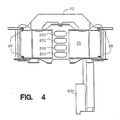
- FIG. 4 is a front view of the ribbon shield 25.
- the shield consists of a thin piece of flexible and resilient plastic film material such as is sold under the trademark Mylar.
- Apertures 25a, 25b, 25c, 25d are located medially along the width of the ribbon shield 25 and are arranged one above the other. Each aperture is positioned to be medial along the height of one ribbon section so that printing can be confined to a predetermined vertical region of the ribbon.
- the rivets 26 mount the ribbon shield 25 to the ribbon guide 23 through mounting holes located toward each of the four corners of the ribbon shield 25.
- FIG. 5 is a perspective view of an alternate embodiment of the present invention, in which a ribbon shield 40 includes a central section 41 which is bowed outward and into a pressure contact with the paper and the platen when the ribbon shield is mounted to the ribbon guide (not shown in this FIG.).
- the central section 41 includes an aperture 42 through which printing may occur, which aperture is aligned with the print head and a selected region of the ribbon.
- This aperture 42 is preferably defined by generally parallel upper and lower edges and semi-circular ends connecting the upper and lower edges in a rounded arc which makes snagging of the ribbon unlikely.
- An upper projection 43 is bent inwardly at approximately a 45 degree angle to provide a ramp which prevents the upper outfolds from catching on the ribbon shield.
- a pair of lower projections 44, also extending inwardly toward the print head are located on the lower edge of the bottom of the central section 41, spaced from the center line of the ribbon shield to allow the ribbon guide to be installed over the print head despite its close proximity to the paper and platen.
- indented sections 45, 46 Immediately adjacent to the central section 41 are indented sections 45, 46 which are spaced rearwardly of the central section.
- Remote ramps 47, 48 are spaced outwardly from the indented sections 45, 46, respectively, and project back outwardly from the indented sections.
- these indented sections 45, 46 allow a pair of retaining clips to pass forward of the indented sections 45, 46 while the retaining clips remain behind a plane passing from the outer edge of the center section 41 to the adjacent remote ramp, 47 or 48. In this manner, paper supported by the platen may pass smoothly over the ramps 47 or 48 and the central section 41 without catching in the clips which secure the ribbon shield 40 in place, all as depicted in connection with FIG. 7.
- Apertures 49 in the indented sections 45, 46 reduce drag on the ribbon as the ribbon passes by the indented sections.
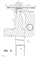
- FIG. 6 illustrates a portion of the printer 10 with the ribbon and ribbon guide of the alternate embodiment of the present invention.
- the printer 10 includes a ribbon box 22 from which a ribbon 54 is threaded to a ribbon guide 55 and back to the ribbon box 22.
- the print head 34 is mounted to the guide rod 35.
- Lower paper guide 31 and upper paper guide 32 are shown directing paper 33 through a lower set of feed rolls 52 and an upper set of feed rolls 53, as might be done with document insertion device (DID) feed modules of the type described in the Paper Module Patent.
- DID document insertion device
- the ribbon shield 40 and its upper and lower projections 43, 44 as well as the aperture 42 are depicted in this view.
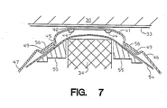
- FIG. 7 illustrates a cross-sectional view of the assembly of FIG. 6, cut along the line VII-VII looking in the direction of the arrow.
- the print head 34 is shown between ribbon guide portions 55.
- Clips 56 extend forward of the ribbon 54 and the ribbon shield in the region of the indented portions 45, 46. These clips extend upwardly, from their connection to the ribbon guide below the ribbon and the ribbon shield, and latch above the upper surface of the ribbon and the ribbon shield, captivating both.
- Aperture 42 is shown in the ribbon shield, through which printing may occur, as well as the apertures 49 in the indented portions.
- the ramps 47, 48 at the distal ends of the ribbon shield are also shown, as is the fact that the clips 56 are depressed below the surface of the ribbon shield central section 41 as it extends to the distal sections 47, 48.
- the paper 33 and the platen 30 are also shown in this view.
- the ribbon shield of either embodiment is, as stated above, advantageously longer in length than the distance between the mounting points, causing it to bow outward and into the paper.
- This bowing puts the ribbon shield into an interference location, as its desired location would be to project perhaps 2 millimeters further.
- This interference causes the ribbon shield to press against the paper and reduce the noise created by the printing operation by one, two or more decibels, depending on the design.
- the present invention (particularly the alternate embodiment using a single-colour ribbon and the paper module illustrated in FIGS. 5-7) has particular application to the use of the interchangeable paper modules disclosed in the referenced Paper Module Patent.
- a cut-paper form such as a rental car agreement may be fed into the printing region after it has been carried by the renter.
- the form may have been folded, creased, or otherwise wrinkled or distorted.
- the present invention comtemplates that such a paper may not be smooth and flat (even moisture can cause paper to wrinkle) and properly directed to feed from the printing station upward into the nip of the rolls of the upper paper handling apparatus.
Landscapes
- Impression-Transfer Materials And Handling Thereof (AREA)
- Handling Of Sheets (AREA)
- Accessory Devices And Overall Control Thereof (AREA)
Applications Claiming Priority (2)
| Application Number | Priority Date | Filing Date | Title |
|---|---|---|---|
| US80792285A | 1985-12-11 | 1985-12-11 | |
| US807922 | 2007-05-30 |
Publications (3)
| Publication Number | Publication Date |
|---|---|
| EP0225498A2 true EP0225498A2 (fr) | 1987-06-16 |
| EP0225498A3 EP0225498A3 (en) | 1989-05-24 |
| EP0225498B1 EP0225498B1 (fr) | 1993-09-22 |
Family
ID=25197436
Family Applications (1)
| Application Number | Title | Priority Date | Filing Date |
|---|---|---|---|
| EP19860115605 Expired - Lifetime EP0225498B1 (fr) | 1985-12-11 | 1986-11-11 | Assemblage d'imprimante à ruban encreur avec une protection intégrale de ruban encreur et méthode d'impression de document |
Country Status (4)
| Country | Link |
|---|---|
| EP (1) | EP0225498B1 (fr) |
| JP (1) | JPS62140869A (fr) |
| DE (1) | DE3689063T2 (fr) |
| ES (1) | ES2003596A6 (fr) |
Cited By (2)
| Publication number | Priority date | Publication date | Assignee | Title |
|---|---|---|---|---|
| EP0771668A1 (fr) * | 1995-08-30 | 1997-05-07 | Seiko Epson Corporation | Masque pour ruban encreur dans une imprimante par points à aiguilles |
| EP0904941A3 (fr) * | 1997-09-30 | 1999-08-18 | Siemens Nixdorf Informationssysteme AG | Imprimante pour substrat d'enregistrement et cartouche à ruban encreur pour utilisation dans une imprimante |
Families Citing this family (2)
| Publication number | Priority date | Publication date | Assignee | Title |
|---|---|---|---|---|
| JPH037375A (ja) * | 1989-06-05 | 1991-01-14 | Fujitsu Ltd | カラーリボン用マスクの実装構造 |
| JPH0460456U (fr) * | 1990-10-03 | 1992-05-25 |
Family Cites Families (7)
| Publication number | Priority date | Publication date | Assignee | Title |
|---|---|---|---|---|
| US4165188A (en) * | 1977-02-17 | 1979-08-21 | Sycor, Inc. | Ribbon mask and guide for dot matrix impact printers |
| US4277187A (en) * | 1979-07-27 | 1981-07-07 | Exxon Research & Engineering Co. | Ribbon locating means |
| US4339211A (en) * | 1979-07-30 | 1982-07-13 | Exxon Research & Engineering Co. | Flexible leader |
| US4383775A (en) * | 1981-02-09 | 1983-05-17 | Data Products Corporation | Ribbon shield |
| JPS5829447U (ja) * | 1981-08-21 | 1983-02-25 | セイコーエプソン株式会社 | 印字装置 |
| US4422785A (en) * | 1982-05-26 | 1983-12-27 | Sydney Shore | Ribbon cartridge construction |
| US4643601A (en) * | 1984-09-28 | 1987-02-17 | International Business Machines Corporation | Ribbon positioning mechanism |
-
1986
- 1986-11-11 JP JP26681986A patent/JPS62140869A/ja active Granted
- 1986-11-11 DE DE19863689063 patent/DE3689063T2/de not_active Expired - Fee Related
- 1986-11-11 EP EP19860115605 patent/EP0225498B1/fr not_active Expired - Lifetime
- 1986-12-10 ES ES8603340A patent/ES2003596A6/es not_active Expired
Cited By (3)
| Publication number | Priority date | Publication date | Assignee | Title |
|---|---|---|---|---|
| EP0771668A1 (fr) * | 1995-08-30 | 1997-05-07 | Seiko Epson Corporation | Masque pour ruban encreur dans une imprimante par points à aiguilles |
| US5785438A (en) * | 1995-08-30 | 1998-07-28 | Seiko Epson Corporation | Ribbon mask for impact dot matrix printed |
| EP0904941A3 (fr) * | 1997-09-30 | 1999-08-18 | Siemens Nixdorf Informationssysteme AG | Imprimante pour substrat d'enregistrement et cartouche à ruban encreur pour utilisation dans une imprimante |
Also Published As
| Publication number | Publication date |
|---|---|
| EP0225498B1 (fr) | 1993-09-22 |
| DE3689063T2 (de) | 1994-04-21 |
| JPH0588198B2 (fr) | 1993-12-21 |
| JPS62140869A (ja) | 1987-06-24 |
| EP0225498A3 (en) | 1989-05-24 |
| ES2003596A6 (es) | 1988-11-01 |
| DE3689063D1 (de) | 1993-10-28 |
Similar Documents
| Publication | Publication Date | Title |
|---|---|---|
| KR100419414B1 (ko) | 테이프카세트 | |
| US4856919A (en) | Pen printer | |
| US4165188A (en) | Ribbon mask and guide for dot matrix impact printers | |
| EP0487314B1 (fr) | Une cassette | |
| US4383775A (en) | Ribbon shield | |
| EP0168193B1 (fr) | Cartouche pour ruban encreur | |
| US4492484A (en) | Improved ribbon mask and guide for wire dot printers | |
| US5098208A (en) | Ribbon cassette with integral paper guide | |
| US4773779A (en) | Printer ribbon cartridge with flexible ribbon guides and integral ribbon shield | |
| US4496256A (en) | Impact printing apparatus | |
| EP0225498A2 (fr) | Assemblage d'imprimante à ruban encreur avec une protection intégrale de ruban encreur et méthode d'impression de document | |
| US5454648A (en) | Printer paper guide | |
| US4676680A (en) | Printing assembly with coloring system | |
| EP0404096A1 (fr) | Dispositif d'introduction de papier pour imprimante | |
| US4571102A (en) | Ribbon mask device | |
| US6189990B1 (en) | Apparatus for leaving space between paper and head of ink-jet printer | |
| US4243334A (en) | Ribbon cartridge | |
| EP0176733B1 (fr) | Elément de guidage flexible | |
| US4431324A (en) | Sound damping ribbon cartridge for a typewriter or similar office machine | |
| EP0104058A2 (fr) | Dispositif d'alimentation en supports d'enregistrement pour une imprimante | |
| US5074689A (en) | Ribbon cassette with integral paper guide | |
| JP2931178B2 (ja) | ラインサーマルプリンタ | |
| EP0535692B1 (fr) | Dispositif de guidage de papier pour imprimante en série | |
| JP3059587U (ja) | 印字装置 | |
| JP3083971B2 (ja) | インクリボンカセット |
Legal Events
| Date | Code | Title | Description |
|---|---|---|---|
| PUAI | Public reference made under article 153(3) epc to a published international application that has entered the european phase |
Free format text: ORIGINAL CODE: 0009012 |
|
| AK | Designated contracting states |
Kind code of ref document: A2 Designated state(s): DE FR GB IT |
|
| 17P | Request for examination filed |
Effective date: 19871023 |
|
| PUAL | Search report despatched |
Free format text: ORIGINAL CODE: 0009013 |
|
| AK | Designated contracting states |
Kind code of ref document: A3 Designated state(s): DE FR GB IT |
|
| RHK1 | Main classification (correction) |
Ipc: B41J 35/26 |
|
| 17Q | First examination report despatched |
Effective date: 19920204 |
|
| GRAA | (expected) grant |
Free format text: ORIGINAL CODE: 0009210 |
|
| AK | Designated contracting states |
Kind code of ref document: B1 Designated state(s): DE FR GB IT |
|
| PG25 | Lapsed in a contracting state [announced via postgrant information from national office to epo] |
Ref country code: IT Free format text: LAPSE BECAUSE OF FAILURE TO SUBMIT A TRANSLATION OF THE DESCRIPTION OR TO PAY THE FEE WITHIN THE PRE;WARNING: LAPSES OF ITALIAN PATENTS WITH EFFECTIVE DATE BEFORE 2007 MAY HAVE OCCURRED AT ANY TIME BEFORE 2007. THE CORRECT EFFECTIVE DATE MAY BE DIFFERENT FROM THE ONE RECORDED.SCRIBED TIME-LIMIT Effective date: 19930922 |
|
| REF | Corresponds to: |
Ref document number: 3689063 Country of ref document: DE Date of ref document: 19931028 |
|
| ET | Fr: translation filed | ||
| PLBE | No opposition filed within time limit |
Free format text: ORIGINAL CODE: 0009261 |
|
| STAA | Information on the status of an ep patent application or granted ep patent |
Free format text: STATUS: NO OPPOSITION FILED WITHIN TIME LIMIT |
|
| 26N | No opposition filed | ||
| PGFP | Annual fee paid to national office [announced via postgrant information from national office to epo] |
Ref country code: GB Payment date: 19951024 Year of fee payment: 10 |
|
| PGFP | Annual fee paid to national office [announced via postgrant information from national office to epo] |
Ref country code: FR Payment date: 19951107 Year of fee payment: 10 |
|
| PGFP | Annual fee paid to national office [announced via postgrant information from national office to epo] |
Ref country code: DE Payment date: 19951123 Year of fee payment: 10 |
|
| PG25 | Lapsed in a contracting state [announced via postgrant information from national office to epo] |
Ref country code: GB Effective date: 19961111 |
|
| GBPC | Gb: european patent ceased through non-payment of renewal fee |
Effective date: 19961111 |
|
| PG25 | Lapsed in a contracting state [announced via postgrant information from national office to epo] |
Ref country code: FR Effective date: 19970731 |
|
| PG25 | Lapsed in a contracting state [announced via postgrant information from national office to epo] |
Ref country code: DE Effective date: 19970801 |
|
| REG | Reference to a national code |
Ref country code: FR Ref legal event code: ST |