EP0225511A2 - Réacteur à eau pressurisée ayant des assemblages de tiges d'entraînement déconnectables en deux pièces - Google Patents
Réacteur à eau pressurisée ayant des assemblages de tiges d'entraînement déconnectables en deux pièces Download PDFInfo
- Publication number
- EP0225511A2 EP0225511A2 EP86115964A EP86115964A EP0225511A2 EP 0225511 A2 EP0225511 A2 EP 0225511A2 EP 86115964 A EP86115964 A EP 86115964A EP 86115964 A EP86115964 A EP 86115964A EP 0225511 A2 EP0225511 A2 EP 0225511A2
- Authority
- EP
- European Patent Office
- Prior art keywords
- drive rod
- rod
- assembly
- clusters
- calandria
- Prior art date
- Legal status (The legal status is an assumption and is not a legal conclusion. Google has not performed a legal analysis and makes no representation as to the accuracy of the status listed.)
- Granted
Links
Images


Classifications
-
- G—PHYSICS
- G21—NUCLEAR PHYSICS; NUCLEAR ENGINEERING
- G21C—NUCLEAR REACTORS
- G21C19/00—Arrangements for treating, for handling, or for facilitating the handling of, fuel or other materials which are used within the reactor, e.g. within its pressure vessel
-
- G—PHYSICS
- G21—NUCLEAR PHYSICS; NUCLEAR ENGINEERING
- G21C—NUCLEAR REACTORS
- G21C19/00—Arrangements for treating, for handling, or for facilitating the handling of, fuel or other materials which are used within the reactor, e.g. within its pressure vessel
- G21C19/20—Arrangements for introducing objects into the pressure vessel; Arrangements for handling objects within the pressure vessel; Arrangements for removing objects from the pressure vessel
- G21C19/207—Assembling, maintenance or repair of reactor components
-
- Y—GENERAL TAGGING OF NEW TECHNOLOGICAL DEVELOPMENTS; GENERAL TAGGING OF CROSS-SECTIONAL TECHNOLOGIES SPANNING OVER SEVERAL SECTIONS OF THE IPC; TECHNICAL SUBJECTS COVERED BY FORMER USPC CROSS-REFERENCE ART COLLECTIONS [XRACs] AND DIGESTS
- Y02—TECHNOLOGIES OR APPLICATIONS FOR MITIGATION OR ADAPTATION AGAINST CLIMATE CHANGE
- Y02E—REDUCTION OF GREENHOUSE GAS [GHG] EMISSIONS, RELATED TO ENERGY GENERATION, TRANSMISSION OR DISTRIBUTION
- Y02E30/00—Energy generation of nuclear origin
- Y02E30/30—Nuclear fission reactors
Definitions
- This invention relates to a pressurized water reactor system of an advanced design incorporating two-piece drive rods assemblies having selectively and remotely actuable, quick-disconnect couplings, and to methods of performing assembly/disassembly and related maintenance operations on such a reactor system.
- control rods which are mounted within the reactor vessel, generally in parallel axial relationship, for axial translational movement in telescoping relationship with the fuel rod assemblies.
- the control rods contain materials known as poisons, which absorb neutrons and thereby lower the neutron flux level within the core. Adjusting the positions of the control rods relative to the respectively associated fuel rod assemblies thereby controls and regulates the reactivity and correspondingly the power output level of the reactor.
- control rods are arranged in clusters, and the rods of each cluster are mounted to a common, respectively associated spider.
- Each spider is connected by corresponding drive rods to a respectively associated adjustment mechanism for raising or lowering the associated rod cluster.
- reactor control rod clusters RCC
- WDRC water displacer rod clusters
- a total of over 2800 reactor control rods and water displacer rods are arranged in l85 clusters, each of the rod clusters being mounted to a respectively corresponding spider.
- the lower barrel assembly may be conventional, having mounted therein, in parallel axial relationship, a plurality of fuel rod assemblies which are supported at the lower and upper ends thereof, respectively, by corresponding lower and upper core plates.
- the rod guides are of first and second types, respectively housing therewithin reactor control rod clusters (RCC) and water displacer rod clusters (WDRC); these clusters, as received in telescoping relationship within their respectively associated guides, generally are aligned with respectively associated fuel rod assemblies.
- One of the main objectives of the advanced design, pressurized water reactors to which the present invention is directed, is to achieve a significant improvement in the fuel utilization efficiency, resulting in lower, overall fuel costs.
- the water displacement rodlet clusters function as a mechanical moderator control, all of the WDRC's being fully inserted into association with the fuel rod assemblies, and thus into the reactor core, when initiating a new fuel cycle.
- a fuel cycle is of approximately l8 months, following which the fuel must be replaced.
- the WDRC's are progressively, in groups, withdrawn from the core so as to enable the reactor to maintain the same reactivity level, even though the reactivity level of the fuel rod assemblies is reducing due to dissipation over time.
- the control rod clusters are moved, again in axial translation and thus telescoping relationship relatively to the respectively associated fuel rod assemblies, for control of the reactivity and correspondingly the power output level of the reactor on a continuing basis, for example in response to load demands, in a manner analogous to conventional reactor control operations.
- the calandria includes a lower calandria plate and an upper calandria plate.
- the rod guides are secured in position at the lower and upper ends thereof, respectively, to the upper core plate and the lower calandria plate.
- Within the calandria and extending between the lower and upper plates thereof is mounted a plurality of calandria tubes in parallel axial relationship, respectively aligned with the rod guides.
- Flow holes are provided in remaining portions of the calandria plates, intermediate the calandria tubes, through which passes the reactor core outlet flow as it exits from its upward passage through the inner barrel assembly.
- the core outlet flow, or a major portion thereof, turns from the axial flow direction to a radial direction for passage through radially outwardly oriented outlet nozzles which are in fluid communication with the calandria.
- the calandria tubes are joined to corresponding flow shrouds which extend to a predetermined elevation within the head, and which in turn are connected to corresponding head extensions which pass through the structural wall of the head and carry, on their free ends at the exterior of and vertically above the head, corresponding adjustment mechanisms, as above noted.
- the adjustment mechanisms have corresponding control shafts, or drive rods, which extend through the respective head extensions, flow shrouds, and calandria tubes and are connected to the respectively associated spiders mounting the clusters of RCC rods and WDRC rods, and serve to adjust their elevational positions within the inner barrel assembly and, correspondingly, the level to which the rods are lowered into the lower barrel assembly and thus into association with the fuel rod assemblies therein, thereby to control the activity within the core.
- each WDRC is approximately 700 lbs. to 800 lbs. in weight
- each group of four (4) such clusters presents a combined weight of in the range of from 2,800 lbs. to 3,200 lbs., requiring that a drive mechanism and associated connecting structure for each group of four clusters have substantial strength and durability, and afford a substantial driving force.
- the CRDM's of well known, electromechanical type associated with corresponding clusters of RCC's were mounted in generally parallel axial relationship, vertically above the dome or head of the vessel and extended in sealed relationship through the head for connection by suitable drive rods to the associated RCC's, and provided for selectively controlled gradual raising and lowering of the RCC's for moderating the reactor energy level, or for rapidly lowering same in the case of shutdown requirements.
- a substitute DRDM which utilizes a hydraulically operated piston which is attached through a corresponding drive rod to each group of associated WDRC's, and which mechanism satisfies the spacing limitations, permitting mounting thereof above the head or dome of the vessel in conjunction with the conventional CRDM's.
- An example of such a hydraulically operated drive mechanism for a WDRC is shown in U.S. Patent No. 4,439,054 - Veronesi, issued March 27, l984 and assigned to the common assignee hereof.
- a further critical design criterion of such reactors is to minimize vibration of the reactor internals structures, as may be induced by the core outlet flow as it passes through the reactor internal structures.
- a significant factor for achieving that criterion is to maintain the core outlet flow in an axial direction throughout the inner barrel assembly and thus in parallel axial relationship relatively to the rod clusters and associated rod guides. This is achieved, in part, by the location of the water inlet and outlet nozzles at an elevation corresponding approximately to that of the calandria assembly, and thus above the inner barrel assembly which housed the rod guides and associated rod clusters, as above noted.
- a one-piece drive rod could be produced by welding together, or using a mechanical joint to connect, plural, shorter components
- the material employed in the drive rods e.g., type 403 stainless steel
- mechanical joints require expensive buttering operations to permit tack welding of locking pins thereto for completing the mechanical assemblage.
- distortions of rod guides may impede the required, free axial movement of the rod guides of the associated clusters which, at a minimum level, would increase the rate of wear and, at a more extreme level, could prevent the smooth, axial/transational movement of the rod guides and associated clusters as is required for their intended control purposes, as above discussed.
- the present invention relates to pressurized water reactors of an advanced design type which requires a substantial increase in the vertical height, or size, of the vessel and, more particularly, to selectively and remotely disconnectable two-piece drive rod assemblies for use in such vessels, and to methods of assembly and disassembly of such vessels made possible through the provision of such drive rod assemblies.
- a pressurized water nuclear reactor of the advanced design type here contemplated employs a large number of reactor control rods, or rodlets, typically arranged in what are termed reactor control rod clusters (RCC) and, additionally, a large number of water displacer rods, or rodlets, similarly arranged in water displacer rod clusters (WDRC), an array of l85 such clusters containing a total of 2800 rodlets (i.e., the total of reactor control rods and water displacer rods) being mounted in parallel axial relationship within the inner barrel assembly of the reactor pressure vessel.
- the rods of each cluster are connected at their upper ends to a corresponding spider, the rods being secured by support mounts connected through corresponding vane assemblies to a control hub of the spider.
- the spider-mounted cluster is received in telescoping relationship within a corresponding rod guide.
- Each spider is connected at its hub through a drive rod to a corresponding adjustment mechanism, which provides for selectively raising or lowering the rod cluster relatively to an associated group of fuel rod assemblies
- a typical water displacer rod (WDRC) cluster may comprise up to 24 water displacer rods mounted in alternating groups of two and four rods on corresponding ones of a total of eight vane assemblies, each of the four-rod assemblies including both a radially extending vane element and a pair of transversely extending vane elements, the latter carrying the cylindrical support mounts at their outer extremeties.
- the total weight of a water displacer rod cluster, thus configured is approximately 700 lbs. to 800 lbs.
- the spiders must support not only the dead weight of the respective rod clusters, but additionally must accommodate the forces imposed thereon both by the environment of the relatively fast-moving core outlet flow which passes thereover and the rod height adjustment functions.
- the adjustment mechanisms for the rod clusters are mounted in generally parallel axial relationship on the head assembly, or dome, of the pressure vessel.
- the control rod cluster drive mechanisms may be a conventional type as employed in the prior art, comprising electromechanically actuated mechanisms which provide for selectively raising and lowering the RCC's to provide the desired level of reactivity within the core and, alternatively, to lower the control rods rapidly in the event of a requirement for rapid shutdown.
- the WDRC's are divided into 22 groups of four clusters each, the WDRC's of each group being selected such that withdrawal of a given one or more of the WDRC groups maintains a symmetrical power distribution within the reactor core.
- the drive mechanisms (DRDM's) for the water displacer rod clusters (WDRC's) may be of the type shown in the above referenced U.S. Patent No. 4,439,054, which are driven hydraulically, and include a latch mechanism which mechanically latches the DRDM rods at a fixed position adjacent the upper end of the stroke.
- the hydraulic mechanisms of the patented type are compatible in physical size with CRDM's, and thus may be accommodated within the available spacings on the vessel head assembly.
- a vent system and preferred method of driving the WDRM's are disclosed in the concurrently filed application, entitled "VENT SYSTEM FOR DISPLACER ROD DRIVE MECHANISM OF PRESSURIZED WATER REACTOR AND METHOD OF OPERATION,” having common coinventors herewith and assigned to the common assignee.
- the method of the present invention and the two-piece drive rod assemblies of the invention as are incorporated in the advanced design pressure vessel and which enable practice of the method of the invention, overcome significant structural, materials, and handling problems of prior art designs and afford additional benefits of minimizing the potential of exposure of maintenance personnel to radiation and other fuel handling concerns.
- the drive rod assemblies which connect the respective RCC's and WDRC's to the respective DRDM's and CRDM's are each formed of two, upper and lower portions, or components; the lower portion, synonymously termed a hub extension, is connected to the hub of the rod cluster spider by a semipermanent joint, and the upper portion, referred to synonymously as the drive rod portion, is connected to the hub extension by a selectively and remotely actuable, quick-disconnect coupling which may be similar to current coupling designs.
- Each of the individual components of the two-piece drive rod assemblies may be smaller than existing, conventional single piece, or unitary, drive rods.
- the selectively disconnectable components of the drive rod assemblies of the present invention avoid the serious problems presented if a single piece drive rod of the unwieldly size, as above explained, were employed.
- the mating components of the selectively and remotely actuable quick-disconnect couplings of the respective WDRC and DRDM drive rod assemblies are compatible in structure and operation, yet configured different so as to be noninterchangeable, thereby assuring that incorrect couplings do not occur. This is a matter of critical concern, in light not only of structural damage, but also of the potentially more serious operating deficiencies which predictably would result, if incorrect couplings were made in the assembly operations.
- assembly/disassembly operations may relate to initial installation of components in a new vessel, as well as, and more typically, to periodic refueling, maintenance and inspection operations, during which various vessel components and associated drive rod assemblies must be separately removed from the vessel and various transported and temporarily stored, followed by subsequent reassembly of the vessel components.
- the advanced reactor design permits refueling operations to be performed in the absence of either control rods or water displacer rods within the lower barrel assembly, or core of the reactor.
- the method of the present invention utilizes this vessel design feature, in conjunction with the selectively disconnectable drive rod assemblies, to remove the upper internals of the vessel as a mass assemblage, for transporting same to a storage stand, permitting work to be performed thereon in parallel with refueling operations required to be performed in the now exposed lower barrel assembly which remains within the vessel.
- the hub extensions thereof are retained within the inner barrel assembly and remain therewith in the upper internals storage stand, while the calandria and associated drive rod portions of the assemblies, now disconnected from the hub portions, are separately transported, en masse, to a second storage stand.
- the calandria with the drive rod portions therein, may be transported back into position over the inner barrel assembly and the drive rod portions reconnected to the corresponding hub extensions with far greater ease, and while maintaining the drive rod portions submerged in the boron charged water.
- This both simplifies the handling tool design and permits an operator to perform "hands-on" control of the handling tool, without having to touch or otherwise be exposed to the drive rod portions themselves.
- drive rods of the requisite length of a unitary or one piece design would not only extend substantially above the water level for substantial time periods during assembly operations, presenting the problems of air contamination and exposure of maintenance personnel to the rods, but also require that maintenance personnel directly engage the rods when aligning same for reconnection to the corresponding clusters.
- the structure of the present invention permits the hub extensions to remain attached to the spider hubs, disposing the upper end of the hub extension carrying the quick disconnect coupling at a position between the top of the rod guide and the adjacent, lower calandria subplate.
- the handling tool does not have to be inserted through the rod guide region at all, and the disconnect coupling on the upper end of the each hub extension is located only some 35′ below the water level, thus greatly simplifying engagement operations and handling tool design.
- the invention in its broad form comprises a pressurized water reactor system comprising: a pressure vessel, said pressure vessel having provided therein, at successively higher elevations: a lower barrel assembly for receiving plural fuel rod assemblies therein in parallel axial relationship, an inner barrel assembly for receiving plural clusters of rods mounted in parallel axial relationship for selectively controlled, axial movement in telescoping relationship with the fuel rod assemblies in a path of travel between a fully inserted position of the rod clusters within the lower barrel assembly and a fully withdrawn position of the rod clusters within the inner barrel assembly, and a head assembly in sealed communication with the lower and inner barrel assemblies for containing the pressurized reactor coolant fluid within the vessel; a plurality of drive means disposed in parallel axial relationship on and extending in sealed relationship through the head assembly; and a plurality of drive rod assemblies respectively connected to said plurality of rod clusters and movable axially therewith through a path of travel corresponding to the movement of the respective rod clusters between the fully withdrawn and the
- Also described and claimed herein is a method of assembling a pressure vessel of a pressurized water reactor system within a containment structure therefor having a level of boron-charged water therein covering the vessel, the vessel having provided therein, at successively higher elevations, a lower barrel assembly for receiving plural fuel rod assemblies therein in parallel axial relationship, an inner barrel assembly for receiving plural clusters of rods, mounted at the upper ends thereof to corresponding, plural mounting means in parallel axial relationship, for selectively controlled, axial movement in telescoping relationship with the fuel rod assemblies between a fully inserted position within the lower barrel assembly and a fully withdrawn position within the inner barrel assembly, the lower barrel assembly having a support plate defining the lower elevation thereof and having a plurality of apertures therethrough corresponding to the plural clusters of rods and receiving same for axial movement therethrough, a calandria assembly disposed above the inner barrel assembly and having a lower calandria plate defining the upper elevation of the inner barrel assembly and an upper calandria
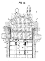
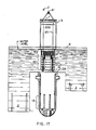
- Fig. l The composite of Figs. lA and lB (referred to hereinafter as Fig. l) is an elevational view, partly in cross-section, of a pressurized water reactor l0 comprising a vessel l2 including an upper dome, or head assembly, l2a, cylindrical sidewalls l2b, and a bottom closure l2c comprising the base of the reactor l0.
- Plural radially oriented inlet nozzles ll and outlet nozzles l3 are formed in the sidewall l2b, adjacent the upper, annular end surface l2d of the sidewall l2b.
- the cylindrical sidewall l2b may be integrally joined, as by welding, to the bottom closure l2c
- the head assembly l2a is removably received on the upper, annular end surface l2d of the sidewall l2b and secured thereto.
- the sidewall l2b further defines an inner, generally annular mounting ledge l2c for supporting various internals structures as later described.
- the lower barrel assembly l6 comprises a generally cylindrical sidewall l7 affixed at its lower end to a lower core plate l8, which is received on mounting support l8b, as generally schematically illustrated.
- the cylindrical sidewall l7 extends substantially throughout the axial height of the vessel l2 and includes an annular mounting ring l7a at the upper end thereof which is received on the annular mounting ledge l2e thereby to support the assembly l6 within the vessel l2.
- the sidewall l7 is solid in the vicinity of the inlet nozzles ll, but includes an aperture l7b having a nozzle ring l7c mounted therein which is aligned with and removably secured to the outlet nozzle l3.
- An upper core plate l9 is supported on a mounting support l7d affixed to the interior surface of the cylindrical sidewall l7 at a position approximately one-half the axial height thereof.
- Fuel rod assemblies 20 are positioned in generally vertically oriented, parallel axial relationship within the lower barrel assembly l6 by bottom mounts 22 carried by the lower core plate l8 and by pin-like mounts 23 carried by, and extending through, the upper core plate l9.
- Flow holes l8a and l9a are provided in predetermined patterns, extending substantially throughout the areas of the lower and upper core plates l8 and l9, the flow holes l8a permitting passage of a reactor coolant fluid into the lower barrel assembly l6 in heat exchange relationship with the fuel rod assemblies 20 defining the reactor core, and the flow holes l9a permitting passage of the core output flow into the inner barrel assembly 24.
- a neutron reflector and shield 2l is mounted interiorly of the cylindrical sidewalls l7, in conventional fashion.
- the inner barrel assembly 24 includes a cylindrical sidewall 26 which is integrally joined at its lower edge to the upper core plate l9.
- the sidewall 26 has secured to its upper, open end, an annular mounting ring 26a which is received on an annular hold-down spring 27 and supported along with the mounting ring l7a on the mounting ledge l2e.
- the sidewall 26 further includes an aperture 26b aligned with the aperture l7b and the output nozzle l3.
- Within the inner barrel assembly 24, and densely packed within the cylindrical sidewall 26, are positioned a plurality of rod guides in closely space, parallel axial relationship; for simplicity of illustration, only two such rod guides are shown in Fig.
- rod guide 28 housing a cluster of radiation control rods 30 (RCC) and a rod guide 32 housing a cluster of water displacement rods 34 (WDRC).
- Mounting means 36 and 37 are provided at the respective upper and lower ends of the rod guide 28 and, correspondingly, mounting means 38 and 39 are provided at the respective upper and lower ends of the rod guide 32, the lower end mounting means 37 and 39 mounting the respective rod guides 28 and 32 to the upper core plate l9, and the upper mounting means 36 and 38 mounting the respective rod guides 28 and 32 to a calandria assembly 50, and particularly to a lower calandria plate 52.
- the calandria assembly 50 includes, in addition to the lower calandria plate 52, an upper calandria plate 54 and a plurality of parallel axial calandria tubes 56 and 57 which are positioned in alignment with corresponding apertures in the lower and upper calandria plates 52 and 54 and to which the calandria tubes 56 and 57 are mounted at their respective, opposite ends. More specifically, calandria extensions 58 and 59 extend through corresponding apertures in and are secured to the lower calandria plate 52, and the corresponding calandria tubes 56 and 57 are respectively secured to the extensions 58 and 59. Similar structures connect the upper ends of the calandria tubes 56 and 57 to the upper calandria plate 54.
- the calandria extensions 58 and 59 For the specific configurations of the respective calandria extensions 58 and 59 as illustrated, only the calandria extensions 58 project downwardly from the lower calandria plate 52 and connect to corresponding mounting means 36 for the upper ends, or tops, of the RCC rod guides 28.
- the upper end mounting means 38 associated with the WDRC rod guides 32, may be interconnected by flexible linkages to the mounting means 36 of the RCC rod guides 28, in accordance with the invention of the pending application, entitled: "FLEXIBLE ROD GUIDE SUPPORT STRUCTURE FOR INNER BARREL ASSEMBLY OF PRESSURIZED WATER REACTOR" -- Gillett et al., assigned to the common assignee herewith.
- the WDRC rod guides 32 may be connected independently to the lower calandria plate 52 by the top end support structure of the invention disclosed in the copending application, entitled: "TOP END SUPPORT FOR WATER DISPLACEMENT ROD GUIDES OF PRESSURIZED WATER REACTOR" -- Gillett et al., assigned to the common assignee hereof.
- the calandria extensions 59 likewise project downwardly from the plate 52, similarly to the extensions 58, to engage and laterally support the WDRC mounting means 38.
- the flared ends 62a, 63a also receive therein the corresponding upper ends 60a, 6la of the flow shrouds 60, 6l in the completed assembly, as seen in Fig. l.
- the head extensions 62, 63 pass through the upper wall portion of the head assembly l2a and are sealed thereto.
- Control rod cluster (RCC) displacement mechanisms 64 and water displacement rod cluster (WDRC) displacement mechanisms 66 are associated with the respective head extensions 62, 63 flow shrouds 60, 6l and calandria tubes 56, 57 which, in turn, are associated with respective clusters of radiation control rods 30 and water displacement rods 34.
- the RCC displacement mechanisms (CRDM's) 64 may be of well known type, as are and have been employed with conventional reactor vessels.
- the displacer mechanisms (DRDM's) 66 for the water displacer rod clusters (WDRC's) 34, as employed with the present invention, may be in accordance with the disclosure of U.S. Letters Patent 4,439,054 - Veronesi, as before noted.
- the respective drive rods associated with the CRDM's 64 and the DRDM's 66 are structurally and functionally the equivalent of an elongated, rigid rod extending from and in association with the respective CRDM's 64 and DRDM's 66 to the respective clusters of radiation control rods (RCC's) and water displacements rods (WDRC's) 30 and 34.
- the CRDM's and DRDM's 64 and 66 thus function through the corresponding drive rods to control the respective vertical positions of, and particularly, selectively to lower and/or raise, the RCC's 30 and the WDRC's 34 through corresponding openings (not shown) provided therefore in the upper core plate l9, telescopingly into or out of surrounding relationship with the respectively associated fuel rod assemblies 20.
- the interior height D1 of the lower barrel assembly l6 is approximately l78 inches, and the active length D2 of the fuel rod assemblies 20 is approximately l53 inches.
- the interior, axial height D3 is approximately l76 inches, and the extent of travel, D4, of the rod clusters 30 and 34 is approximately l49 inches. It follows that the extent of travel of the corresponding CRDM and DRDM drive rods is likewise approximately l49 inches.
- the WDRC's 32 through their respective drive rods (not shown in Fig. l) and DRDM's 66, then are selectively removed as the excess reactivity is depleted, over the fuel cycle. Typically, this is performed by simultaneously removing a group of four such WDRC's 34 from their fully inserted positions in association with the fuel rod assemblies 20, to a fully raised position within the corresponding WDRC guides 32 and thus within the inner barrel assembly 24, in a continuous and controlled withdrawal operation. More specifically, the four WDRC's 34 of a given group are selected so as to maintain a symmetrical power balance within the reactor core, when the group is withdrawn.
- WDRC's 34 typically remain fully inserted in the fuel rod assemblies 20 for approximately 60% to 70% of the approximately l8 month fuel cycle. Groups thereof then are selectively and successively moved to the fully withdrawn position as the excess reactivity is depleted, so as to maintain a nominal, required level of reactivity which can sustain the desired output power level, under control of the variably adjustable RCC's 30.
- the vent system of the related invention thus serves to provide hydraulic energizing fluid to the DRDM's 66 in accordance with selectively controlling the WDRC raising and lowering functions, as above described.
- the reactor coolant fluid, or water, flow through the vessel l0 proceeds generally from a plurality of inlet nozzles ll, one of which is seen in Fig. l, downwardly through the annular chamber between an outer generally cylindrical surface defined by the interior surface of the cylindrical sidewall l2b of the vessel l2 and an inner generally cylindrical surface defined by the cylindrical sidewall l7 of the lower barrel assembly l6.
- the reactor coolant flow proceeds as well into the chamber defined by the head assembly l2a through certain bypass passageways (not shown in Fig. l), associated with the mounting of the calandria tubes 56 and 57 to the upper calandria plate 54 and also in accordance with the connections of the head extensions 62, 63 and the flow shrouds 60, 6l.
- certain bypass passageways not shown in Fig. l
- Pertinent to the present invention are the flared ends 62a and 63a of the corresponding head extensions 62, 63 which function to guide the corresponding flow shrouds 60, 6l into alignment during assembly of the head assembly l2a with the sidewall l2b to achieve the assembled relationship illustrated in Fig. l.
- the pressure of the cycle water, or reactor coolant, within the vessel l0 typically is in the range of about 2,250 psi, and provides the energy source, or fluid pressure, to the DRDM's 66 for raising the DRDM drive rods from a fully inserted to a fully withdrawn, or up position, as described more fully in the related, above-identified application.
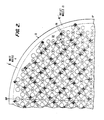
- Fig. 2 is a cross-sectional, schematic bottom planar view of the lower calandria plate 52 at a position, in Fig. l, intermediate the mounting means 36 and 38 for the RCC and WDRC rod guides 28 and 32, respectively, and the plate 53; further, Fig. 2 is on an enlarged scale, and represents only a quadrant of the internal structure of the calandria 50 for illustrating diagramatically the dense packing of the arrays of plural control and water displacer rod clusters 30 and 34 within the inner barrel assembly 24.
- Each of the circles labelled “D” designates an aperture, or hole, in the calandria plate 52 through which is received a corresponding DRDM drive rod, associated with a corresponding WDRC cluster 34; similarly, each of the circles marked “C” designates an aperture in the calandria plate 52 through which is received a corresponding CRDM drive rod, associated with a corresponding RCC cluster 30.
- These apertures C and D provide fluid communication with the corresponding RCC and WDRC calandria tubes 56 and, particularly, through the shrouds 6l and head extensions 63 for communicating the reactant coolant pressure to the DRDM's 66.
- the remaining unlabelled circles in the lower calandria plate 52 in Fig. 2 correspond to the apertures 52a shown in Fig. l, which provide for communicating the reactor coolant flow from the inner barrel assembly 24 to the calandria 50.
- Elements 74 comprise leaf springs which are mounted by bolts 76 to the calandria lower plate 52 in oppositely oriented pairs, generally in alignment with the diameters of the RCC associated apertures "C", in an alternating, orthogonally related pattern.
- the free ends of the springs 74 bear downwardly upon the upper surfaces of the RCC mounting means 36 of a next-adjacent aperture "C,” so as to provide a frictional force opposing lateral displacement thereof and accordingly of the associated rod guide 28, while affording a degree of flexibility to the axial position of the rod guide.
- springs 74 is one preferred structural mounting means for the RCC guides, in accordance with the disclosure of the above noted, copending application, entitled: "FLEXIBLE ROD GUIDE SUPPORT STRUCTURE FOR INNER BARREL ASSEMBLY OF PRESSURIZED WATER REACTOR,” alternative mounting means may be employed for this purpose and thus the foregoing described structure is not to be deemed limiting in any sense, but merely illustrative.
- Fig. 2 also illustrates the relative locations of the plural inlet and outlet nozzles ll and l3 as seen in Fig. l, it being understood that the quadrant of the vessel shown in the plan view of Fig. l2 is reflected as a mirror image about the 90° axis illustrated thereon and the combined configuration then is reflected about the 0°/l80° axis to establish the full (360°) configuration of the vessel l2.
- a total of four inlet nozzles ll two being equiangularly displaced about each of the 90° and 270° positions
- the RCC clusters and WDRC clusters are disposed in densely packed, interleaved arrays, substantially across the entire cross-sectional area of the inner barrel assembly 24.
- the RCC and WDRC rod clusters 30 and 34 are supported by corresponding spiders l00 and l20, as illustratively shown in Figs. 3 to 6, in turn connected through corresponding drive rods to the CRDM's 64 and DRDM's 66, an example of the DRDM 66 being shown in Figs. 7 and 8, as hereafter described.
- Figs. 3 and 4 are plan and elevational views of an RCC spider l00, Fig. 3 being schematic in form and Fig. 4 being a partly broken-away, cross-sectional view taken along the line 4-4 in Fig. 3.
- the RCC spider l00 comprises a central hub l02 of generally cylindrical configuration having an upper, interiorally threaded end l03 for connection to a drive rod (not shown) which extends, as before described, upwardly to an RCC adjustment mechanism 64 by which the spider l00 and its associated control rods 30 (Fig. l) may be vertically adjusted in position within and relative to the RCC rod guide 28 and correspondingly relative to the fuel rod assemblies 20, of Fig. l.
- Vane assemblies l06 are secured at the respective inner edges thereof to the hub l02 and extend radially therefrom in quadrature, relative relationship.
- Each vane assembly l06 includes a pair of cylindrically-shaped rod support mounts l08, each thereof having an interior bore l09 including an interiorally threaded portion ll0 into which the upper, correspondingly threaded end of a control rod (not shown) is threadingly engaged so as to be supported by the vane assembly l06 and corresponding hub l02.
- Figs. 5 and 6 illustrate a WDRC spider l20, Fig. 5 being a planar, generally schematic view, and Fig. 6 being an elevational view, partially in cross-section and taken along the line 6-6 in Fig. 5.
- the WDRC spider l20 includes a central hub l22 of generally cylindrical configuration, the upper end l23 being interiorally threaded to receive a drive rod which, as discussed in connection with Fig. l, connects to a corresponding WDRC control mechanism 66.
- First and second types of vane assemblies l26, l27 are connected to the hub l22 in alternating, equiangularly displaced relationship so as to extend radially therefrom.
- the vane assemblies l26 are substantially similar to the RCC vane assemblies l06, as seen in Figs. 3 and 4, and thus include a pair of radially displaced WDRC rod support mounts l28. As best seen in Fig. 5, the vane assemblies l26 are disposed to extend radially from the hub l22 in quadrature relationship, each intermediate an adjacent quadrature-related pair of vane assemblies l06 in the alternating sequence as above described.
- the vane assemblies l27 include integral, transverse vanes l25 extending from the integral radial vane segments l23′ and l24′ as first and second aligned and oppositely oriented pairs l25A and l25B, each thereof carrying a WDRC rod support mount l28 at its extremity.
- Each of the WDRC rod support mounts l28 includes a threaded bore l29 at its lower extremity for receiving, in threaded engagement therein, the top end of a corresponding WDRC rod.
- the vane assemblies l06 and l26 include corresponding first and second planar vane elements ll2, ll4 and l23, l24, respectively, each thereof having longtitudinal flanges for connecting the associated vane assemblies l06 and l26 to the respective, RCC spider hub l02 and WDRC spider hub l22.
- This structure is illustrated for the RCC spider l00 in Fig. 4 by the receiving slot lll in the hub l02 and the flange ll5 received therein, and is illustrated for the WDRC spider l20 in Fig. 6 by the receiving slot l2l in the hub l22 and the flange l3l associated with the first planar vane element l23, received therein.
- the second type of vane assembly l27 of the WDRC spider l20 corresponds substantially to the first vane assembly l26 in that it includes first and second planar vane element portions l23′ and l24′ which are integrally formed and extend radially from the hub l22, the first portion l23′ having a longitudinal flange l3l′ received in a corresponding receiving slot l2l′ in the hub l22.
- the assembly l27 furthermore includes first and second pairs l25a and l25b of third planar vane elemnts l25 integrally formed with an extending transversely from the first and second integral vane element portions l23′ and l24′, the first pair l25a being formed intermediate the portions l23′ and l24′ and the second pair l25b being formed on the outer longitudinal edge of the second vane element portion l24′.
- Each of the elements l25 carries a rod support mount l28 on its outer longitudinal edge.
- the third, or transverse, planar vane elements l25 may include similar flange structures on their outer longitudinal edges for mounting the corresponding rod support mounts l28.
- the innermost planar vane elements ll2, and l23, l23′ preferably are positioned with the respective flanges ll5 and l3l, l3l′ inserted into the corresponding receiving slots lll and l2l, l2l′ of the associated hubs l02 and l20, and then spot welded in place at the upper and lower extremities thereof, as indicated by weld beads. Thereafter, the joints are brazed along the entirety of the lengths thereof.
- the displacer rod drive mechanism (DRDM) 66 receives a drive rod l32 which is connected to a WDR spider l20.
- the DRDM 66 is shown more fully in the noted U.S Patent No. 4,439,054.
- the DRDM 66 comprises a substantially cylindrical metal housing l36 which is welded to a head extension 62, which extends through the dome, or head l2a.
- Housing l36 has a cap l38 attached to the top thereof which has a channel l40 therethrough that is connected to conduit 80, as shown in Fig. l.
- a bearing housing l46 is removably disposed within housing l36 and has a plurality of first piston rings l48 attached to the outside thereof near its lower end which extend into contact with the inside of housing l36 for aligning bearing housing l46 within housing l36 but allowing for the removal of bearing housing l46.
- Drive rod l32 is slidably disposed within bearing housing l46 in a manner so as to be able to be moved axially with respect to bearing housing l46 and housing l36 under the influence of the reactor coolant pressure.
- a plurality of second piston rings l50 which may be Inconel, are removably disposed within bearing housing l46 so as to be able to contact drive rod l32.
- Second piston rings l50 provide a mechanism for allowing drive rod l32 to slide within bearing housing l46 while limiting the flow of reactor coolant through bearing housing l46 and housing l36 when the vent system permits fluid flow through conduit 80, the movement of drive rod l32 thus being controlled by the vent system of the invention.
- Second piston rings l50 are arranged so that they may be replaced when bearing housing l46 is removed from housing l36.
- a plurality of roller bearings l52 are disposed on a like number of axles l54 in a manner so as to allow the outer surface of roller bearings l52 to contact the outer surface of drive rod l32 while allowing the rotation of roller bearings l52.
- four roller bearings l52 may be used so as to align drive rod l32 within bearing housing l46 while aiding in the movement of drive rod l32.
- a plurality of screws l56 corresponding to the number of roller bearings l52 are used to attach holding member l58 to bearing housing l46 so as to hold roller bearings l52 within bearing housing l46 yet allow replacement thereof by removal of screws l56 and holding member l58.
- a second set of roller bearings l60 are disposed at the other end of bearing housing l46 to provide alignment of drive rod l32.
- drive rod l32 has a flexible rod l62 attached to the top end thereof which may be an Inconel rod.
- Flexible rod l62 has a spear-shaped member l64 attached to its top end.
- a hollow cylindrical divider l66 is attached to the lower end of cap l38, in colinear alignment with channel l40.
- Divider l66 defines chambers l68, l69 and l70 in the bottom end of cap l38, each of a size to accommodate the spear member l64.
- the spear-shaped member l64 cooperates with a pivoted latch mechanism l72 in a manner more fully described in U.S. Patent No. 4,439,054.
- the latch l72 is normally spring biased to the slanted, or angularly offset position indicated in Fig. 7, and is mounted for pivotal movement in a clockwise direction in which the right-hand side thereof engages the interior of the wall of housing l36.
- the spear-shaped member moves upwardly along the slanted surface of the latch mechanism l72 as indicated in phantom lines, ultimately passing beyond the upper edge thereof and being received in the first chamber l68, the latch l72 being deflected by that movement to pivot in a clockwise direction and provide clearance for the motion of the spear shaped member l64 and then returning to its initial position by the spring biasing.
- cap l38 functions as a stop to prevent further upward movement of the member l64 and thus the drive rod l32.
- the weight of the rod l32 and attached WDRC cluster causes the same to fall by gravity, the member l64 being received in the first bore l78 of the latch l72 and supported on ledge l82 to stop the downward movement, this action furthermore pivoting latch l72 to a vertically aligned position thus locking, or parking, the rod l32 in its up position.
- the drive rod l32 thus must perform an over-travel movement, so as to be engaged and locked by the latch l72.
- the vent system produces a pressure differential within the DRDM 66 which acts on the rod l32 so as to drive it upwardly through the bore l78 and into the central chamber l70, upward movement again being halted by the lower surface of cap l68 which acts as a stop on the element l64.
- latch mechanism l72 includes suitable slots in the generally vertically oriented sidewalls thereof through which the flexible rod l62 may pass, to permit movement thereof transversely through the sidewalls defining the bores l78 and l80 of the latch mechanism l72, the slots of course being smaller than the element l64, which travels through the bores l78 and l80, as above described.
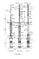
- Figs. 9A and 9B comprise schematic, partially broken away, elevational views of the internals of a reactor vessel l2, as shown in Fig. l, for illustrating the relationships of the RCC and WDRC clusters 28 and 32 relatively to major components of the pressure vessel l2 of Fig. l, when the corresponding RCC and WDRC clusters 28 and 3l in Figs. 9A and 9B, respectively are in each of the fully inserted ("FI") fully withdrawn (“FW”), and refuelling ("REF”) positions, as designated in each of the figures.
- FI fully inserted
- FW fully withdrawn
- REF refuelling
- the corresponding RCC spider l00 and WDRC spider l20 are at the bottom of the corresponding rod guides 28 and 32, supported on the upper core plate l9, with the associated rods thereof in telescoped, fully inserted relationship with the fuel rod assemblies 20.
- the spiders l00 and l20 are closely adjacent the lower calandria plate 52, and the lower ends of the corresponding rods are disposed just above the top ends of the fuel rod assemblies 20.
- Figs. 9A and 9B best illustrate the selectively disconnectable CRDM drive rod assembly 200 and DRDM drive rod assembly 20l in accordance with the present invention. While the couplings which interconnect the components of the CDRM and DRDM drive rod assemblies have differently keyed coupling elements to prevent erroneous interconnection of the respective components and thus to assure that only the CDRM components may be interconnected within the CRDM drive rod assembly 200 and, correspondingly, only DRDM components may be interconnected within the DRDM drive rod assembly 20l, the basic configurations are substantially similar. Accordingly, in the following, reference will be had concurrently to Figs. 9A and 9B, the odd and even reference numbers respectively relating to the components of the DRDM drive rod assembly 200 of Fig. 9A and to the components of the DRDM drive assembly 20l of Fig 9B.
- the CRDM and DRDM drive rod assemblies 200 and 20l respectively comprise hub extensions 202, 203 connected to the hubs l02, l22 of the RCC spider l00 and WDRC spider l20 by semipermanent couplings or joints 204, 205 and drive rod portions 206, 207 connected to the respective hub extensions 202, 203 by selectively and remotely actuable quick disconnect couplings 208, 209.
- the common, dimensional reference D4 in each of Figs. 9A and 9B indicates the path of travel of the drive rod assemblies 200, 20l between the fully withdrawn and the fully inserted positions, as referenced to the corresponding positions of the quick disconnect couplings 208, 209 in those respective positions.
- the common distance D4 of Figs. 9A and 9B corresponds to the distance D4 in Fig. lA, which in one actual embodiment of the vessel l2 is approximately l49".
- the overall height of the inner barrel assembly 24, on the other hand, may be approximately l76".
- the interior height, D1 of the lower barrel assembly l6 is approximately l78 and the active fuel length, D2, of the fuel rod assemblies 20 is approximately l53", the lower ends of the fuel rod assemblies being displaced by approximately 7" from the upper surface of the lower core plate l8.
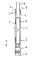
- Fig. l0 is a longitudinal cross-sectional view of the drive rod portion 206 of the CRDM drive rod assembly 200, corresponding to the similarly configured view of the drive rod portion 207 of the DRDM drive rod assembly 20l of Fig. ll.
- the drive rod portions 206, 207 comprise elongated, generally cylindrical, hollow housings 2l0, 2ll having annular recesses, or necks 2l2, 2l3 adjacent the upper ends thereof, for a purpose to be described.
- Disconnect rods 2l4, 2l5 extend throughout the length of the housings 2l0, 2ll and project beyond the lower ends thereof, the projecting portions including shoulders 2l6, 2l7 joining reduced diameter shanks 2l8, 2l9, on which annular positioning nuts 220, 22l are received and secured thereto by lock pins 222, 223.
- Couplings 224, 225 of generally cylindrical, hollow configuration, and having keyed, ribbed flexure ends 226, 227 are positioned over the drive rods 2l4, 2l5 and threaded at their upper ends 228, 229 onto threaded end portions 2l0a, 2lla, of the housings 2l0, 2ll and secured thereto by pins 230, 23l.
- the flexure ends 226, 227 comprise keyed, male coupling components of the quick disconnect couplings 208, 209 of Figs. 9A and 9B.
- Annular buttons 232, 233 are received on the reduced diameter shanks portions 2l8, 2l9 and have outer, mating surfaces engaging the general conical interior surfaces 226a, 227a, of the flexure ends 226, 227.
- Springs 234, 235 are received over the disconnect rods 2l4, 2l5, and compressed between the buttons 232, 233 at the lower ends thereof and retainers 236, 237 which are received within the bore of the housing 2l0, 2ll and positioned against annular retainer ledges 238, 239 so as to urge the respective buttons 232, 233 to the extended positions indicated, engaging the conical interior surfaces 226a, 227a.
- Generally cylindrical, protective sleeves 240, 24l are received about the respective couplings 224, 225 and threadingly engaged thereon and secured in place by corresponding locking pins 242, 243.
- the upper ends of the housings 2l0, 2ll incorporate spring housings 244, 245 of relatively enlarged diameters, defining corresponding shoulders therewithin, the respective disconnect rods 2l4, 2l5 including enlarged diameter portions 246, 247 on which retainer collars 248, 249 are secured, disposed in the housings 244, 245.
- Corresponding spring retainers 250, 25l are secured in an upper portion of the housings 244, 245; springs 252, 253 received over the disconnect rods 2l4, 2l5 extend in compression between the spring retainers 250, 25l and the retainer collars 248, 249, forcing the corresponding drive rods 2l4, 2l5 in an axially downward direction toward the flexure ends 226, 227 and maintaining the positioning nuts 220, 22l in the indicated positions, substantially flush with the open end surfaces of the flexure ends 226, 227.
- a disconnect button 254 of generally cylindrical, hollow configuration and having a reduced diameter annular recess, or neck, 254a is received over the upper end of the disconnect rod 2l4 and secured thereto by pin 256.
- a spring 258 is received in an annular, recessed spring seat 258a at the upper end of housing 2l0.
- the lower cylindrical portion 254b of the disconnect button 254 is of enlarged diameter, defining a shoulder 254c disposed to engage the spring 258 which thus provides a resilient restraint against vertically upward movement of the button 254 (i.e., to the left in Fig. l0) which would tend to eject the button 254 from within the housing 20l, while additionally serving to center the button 254 coaxially therewithin.
- the lower end 254d of the button 254 engages a corresponding shoulder 260 within the housing 2l0 which establishes the downward limit of travel of the button 254.
- a disconnect button 255 having a reduced diameter, annular recess, or neck 255a is received on the upper end of the disconnect rod 2l5 and secured thereto by lock pin 257. Additionally, the disconnect button 255 is received over a locking collar 259 secured to the disconnect rod 2l5 by a pin 26l.
- the disconnect button 255 is received within the upper interior portion 263 of the housing 2ll, the portion 263 being interiorally threaded as shown at 263a.
- the neck 255a of the button 255 is accessible through slots 265 from the exterior of the housing 2ll, for a purpose to be described.
- the DRDM assembly 20l includes a piston 27l having a lower, threaded shank portion 27la received in threaded engagement in the threaded interior portion 263a and secured thereto by pin 273.
- Piston rings 275 are recessed into the surface of the piston 27l.
- the piston 27l carries a flexible shaft l62′ and a spear-shaped head element l64′ which perform the identical functions as the corresponding, but unprimed, numbered elements in Figs. 7 and 8.
- the disconnect function is performed with respect to each of the CRDM and DRDM drive rod assemblies 200, 20l in substantially similar ways, albeit with modifications to take into account the somewhat differing structures thereof.
- a tool is positioned on the upper end of the housing 2l0 so as to engage the reduced diameter neck 2l2 of housing 2l0 and the neck 254a of the disconnect button 254, and then is actuated to drive the disconnect button 254 axially outwardly, thereby to withdraw or retract the disconnect rod 2l4 and the associated positioning nut 220 and spring button 232 from within the interior of the flexure end 226, permitting the latter to collapse.
- a similar tool is positioned adjacent the upper end of housing 2ll so as to engage the reduced diameter neck 2l3 of the housing 2ll and the reduced diameter neck 255a of the button 255, the latter through the slots 265.
- the tool is actuated so as to move the button 255 into the open interior portion 263 at the upper end of the DRDM housing 2ll and thereby retract the associated disconnect rod 2l5 and the corresponding positioning nut 22l and button 233, against the resilient biasing of the spring 235 (which serves to hold button 233 in place against the mating interior surface 227a of the flexure end 227), compressing both springs 235 and 253.
- the resulting disposition of the parts is shown in Fig.
- Fig. l2 thus indicates the corresponding, disengaged condition of the flexure end 226 of the drive rod portion 206 of the CRDM assembly 200, shown in Fig. l0.
- Figs. l3A and l3B are longitudinal cross-sectional views of the hub extensions 202 and 203 of the CRDM and DRDM drive rod assemblies 200 and 20l, respectively.
- the hub extensions 202, 203 comprise female coupling elements 280, 28l having interior, keyed surfaces 280a, 28la which mate the exterior, keyed surfaces of the male flexure ends 226, 227 of the CRDM and DRDM drive rod portions 206, 207 and, taken together, comprise the quick disconnect couplings 208, 209 of the respective assemblies 200, 20l as shown in Figs. 9A and 9B.
- the coupling elements 280, 28l include interiorally threaded end portions 280b, 28lb which are received on the corresponding, threaded upper end portion of the corresponding hub extensions 202, 203.
- Male, semipermanent joint elements 290, 29l comprising components of the semipermanent joints 204, 205 (Figs. 9A and 9B), are of generally cylindrical configuration and include interiorally threaded end portions 290a, 29la by which they are threadingly received on correspondingly threaded lower end portions of the hub extensions 202, 203 and secured in place by pins 292, 293.
- the male joint elements 290, 29l include stub portions 294, 295, the former being of larger diameter and lesser axial length than the latter, and each having threaded surfaces 294a, 295a.
- Locking sleeves 296, 297 are received on an enlarged diameter, central portion of the elements 290, 29l and secured in place by indents 298, 299.
- the remotely and selectively actuable, quick disconnect couplings 208 and 209 of the CRDM and DRDM drive rod assemblies 200 and 20l of Figs. 9A amd 9B, respectively, thus include as the male components thereof the respective CRDM flexure end 226 of Fig. l0 and DRDM flexure end 227 of Fig. ll and, as the respectively corresponding female components, the CRDM coupling element 280 of Fig. l3A and the DRDM female coupling element 28l of Fig. l3B.
- the male CRDM coupling component comprising the flexure end 226 (Fig. l0) is of shorter axial length than the male DRDM coupling element comprising the flexure end 227 (Fig.
- the male DRDM coupling element comprising the flexure end 227 is of greater axial length than the female CRDM coupling element 280, and the respective keyed surfaces 227a and 280a are axially relatively displaced, such that if the former is accidentally inserted into the latter, the keyed exterior surfaces of the DRDM male flexture end 226 and the interior keyed surface of the female CRDM coupling element 280 would not achieve a mating, or aligned relationship. In both cases of such possible, accidental partial insertion, release of the disconnect button would not result in the positioning nuts 220, 22l returning to engaged position and coupling the corresponding flexure ends 226, 227 to the incorrect female coupling components.
- the semipermanent CRDM joint 204 and DRDM joint 205 (Figs. 9A and 9B), while of similar configurations, nevertheless are noninterchangeable, so that erroneous interconnections cannot occur.
- the interiorally threaded portion l03 of hub l02 of the RCC spider l00 comprises the female component of the semipermanent joint 204 which receives the threaded male stub 294 of the CRDM hub extension 202, these components being of relatively wider diameter but shorter axial length than the corresponding DRDM male stub 295 (Fig. l3B) and female, interiorally threaded portion l23 of the WDRC hub l22 (Fig. 6).
- the locking sleeves 282, 283 are received coaxially over the hubs l02, l22; recesses l02a and l22a in the hubs l02 and l22 (see Figs. 3 and 5, respectively) permit formation of corresponding indents in the locking sleeves 282, 283 for locking the joints 204, 205 and thereby prevent accidental disassembly.
- the respective joints 204, 205 are characterized as semi-permanent, inasmuch as by the application of sufficient rotary torque, the hubs l02, l20 may be unscrewed from the hub extensions 202, 203, releasing the indents from one or the other of the elements 290, 29l or the hubs l02, l20, and thereby separating the hub extensions 202, 203 from the corresponding spiders l00, l20.
- FIG. l2 Schematically illustrated in association with the vessel l2 are standard components of the containment structure l of a typical nuclear reactor installation, including a first, upper internals storage stand 2 and a second, lower internals storage stand 3, the structure l being able to maintain within a required level of boron-charged water, as indicated in Fig. l4.
- the water level typically is at an elevation of approximately 98 feet.
- a floor 6 is supported a few feet above the water level, as indicated in Fig. l4.
- the respective CRDM and DRDM drive rod assemblies 200, 20l project upwardly above the ledge l2d of the vessel l2 in this condition.
- the spreader assembly 7 then is raised, withdrawing the drive rod assemblies 200, 20l, to the refueling position "REF" as described with reference to Figs. 9A and 9B.
- the drive rod assemblies 200, 20l extend for the full length of some 34 feet from their connections (at the semipermanent joints) to the spiders immediately beneath the calandria 50, extending therefore several feet above the water level. It is significant that the entirety of this operation can be performed remotely and thus, although the drive rods 200 and 20l are exposed above the water level, no adverse conditions are created. Specifically, release of contaminants into the air is a minimum risk, since the drive rods remain wet, supressing release of any surface contamination, and the movement en masse , of the unitary assembly can be performed rapidly.
- the lifting rig 5 transports the raised upper internals over the upper ledge l2d of the vessel l2 and into position over the upper internals storage stand 2.
- the rig 5 lowers the entire assembly onto the stand 2 and the spreader assembly 7 then is lowered, causing the rod clusters (illustratively indicated by a single RCC cluster 30 and a single WDRC cluster 34) to move downwardly to their fully inserted positions.
- the upper core plate l8 is at an elevation of approximately 48 feet, leaving a distance of approximately 50 feet to the bottom of the containment structure l, into which underlying portion the RCC and WDRC rod guides 30, 34 extend.
- the corresponding spiders l00 and l20 (not shown in Fig. l8, but see Figs. 9A and 9B) rest on the upper core plate l8 and thus support the RCC and WDRC rod clusters within the corresponding rod guides 30 and 34.
- the lower calandria plate 52 is some 35 feet below the water level, and the ledge l2d of the vessel l2 is approximately 27 feet beneath the water level.
- the upper ends of the drive rod assemblies 200, 20l and, correspondingly, the spreader assembly 7, are at an elevation of some l5 feet below the water level.
- the drive rod assemblies 200, 20l thus are readily accessible by appropriate handling tools for actuation of the disconnect buttons, thereby to release the drive rod portions 206, 207 at the corresponding quick disconnect couplings 208, 209 (which currently are positioned beneath, but closely adjacent the lower calandria plate 52, corresponding to the fully inserted positions of Figs. 9A and 9B, and thus at the approximately 35-foot elevation).
- the rig 5 then raises the calandria 50 vertically while simultaneously raising the spreader assembly 7, to a sufficient elevation to position the lower calandria plate 52 approximately one foot above the ledge l2d of the vessel l2, for transporting same to the lower internals storage stand 3 and, as shown in Fig. 20, then lowers the mass assemblage of the calandria l5 and the drive rod portions 206, 207 onto the support stand 3.
- the fuel assemblies 20 and the rod clusters 30, 34 may be withdrawn individually for inspection, repair or the like or, in the case of the fuel assemblies 20, for purposes of relocating same within the core or to perform routine fuel exchange operations.
- the drive rod portions 206, 207 may include stops so as to prevent them from falling downwardly through the calandria 50 or alternatively they may be permitted to drop to the bottom of the containment structure l, while remaining laterally supported by the calandria 50. They as well may be withdrawn for inspection and/or replacement, while the calandria 50 is positioned in stand 3.
- the corresponding quick disconnect couplings 208, 209 are disposed at an elevation of only some 35 feet below the water level, greatly facilitating the coupling operations, while nevertheless assuring adequate protection to personnel involved in performing the reassembly operations. It will now be apparent that the provision of the differentiated, or noninterchangeable configurations of the components of the couplings 208, 209, serves to assure that the CRDM and DRDM drive rod portions 206, 207 cannot be inadvertently attached to the incorrect hub extensions, and instead that they can and will be attached only to the correct CRDM and DRDM hub extensions 202, 203, respectively.
Landscapes
- Physics & Mathematics (AREA)
- Engineering & Computer Science (AREA)
- Plasma & Fusion (AREA)
- General Engineering & Computer Science (AREA)
- High Energy & Nuclear Physics (AREA)
- Monitoring And Testing Of Nuclear Reactors (AREA)
- Transmission Devices (AREA)
- Paper (AREA)
Applications Claiming Priority (2)
| Application Number | Priority Date | Filing Date | Title |
|---|---|---|---|
| US06/806,711 US4778645A (en) | 1985-12-09 | 1985-12-09 | Pressurized water reactor having disconnectable two-piece drive rod assemblies, and related methods of assembly and maintenance operations |
| US806711 | 1985-12-09 |
Publications (3)
| Publication Number | Publication Date |
|---|---|
| EP0225511A2 true EP0225511A2 (fr) | 1987-06-16 |
| EP0225511A3 EP0225511A3 (en) | 1988-07-27 |
| EP0225511B1 EP0225511B1 (fr) | 1992-09-02 |
Family
ID=25194667
Family Applications (1)
| Application Number | Title | Priority Date | Filing Date |
|---|---|---|---|
| EP86115964A Expired - Lifetime EP0225511B1 (fr) | 1985-12-09 | 1986-11-18 | Réacteur à eau pressurisée ayant des assemblages de tiges d'entraînement déconnectables en deux pièces |
Country Status (5)
| Country | Link |
|---|---|
| US (1) | US4778645A (fr) |
| EP (1) | EP0225511B1 (fr) |
| JP (2) | JP2551419B2 (fr) |
| KR (1) | KR950001247B1 (fr) |
| ES (1) | ES2034955T3 (fr) |
Cited By (4)
| Publication number | Priority date | Publication date | Assignee | Title |
|---|---|---|---|---|
| FR2632112A1 (fr) * | 1988-05-27 | 1989-12-01 | Westinghouse Electric Corp | Support temporaire d'equipements internes inferieurs de cuve de reacteur |
| CN110114837A (zh) * | 2016-12-30 | 2019-08-09 | 纽斯高动力有限责任公司 | 具有远程断开机构的控制棒驱动机构(crdm) |
| US11355252B2 (en) | 2016-12-30 | 2022-06-07 | Nuscale Power, Llc | Control rod drive mechanism with heat pipe cooling |
| US11631503B2 (en) | 2016-12-30 | 2023-04-18 | Nuscale Power, Llc | Control rod damping system |
Families Citing this family (14)
| Publication number | Priority date | Publication date | Assignee | Title |
|---|---|---|---|---|
| US4859404A (en) * | 1988-06-29 | 1989-08-22 | Westinghouse Electric Corp. | Reactor vessel internals storage area arrangement |
| US5669729A (en) * | 1996-01-11 | 1997-09-23 | Framatome Cogema Fuels | Reconstitutable rod cluster control assembly |
| US5711629A (en) * | 1996-01-11 | 1998-01-27 | Framatome Cogema Fuels | Reconstitutable rod cluster control assembly with biased driver |
| US6327322B1 (en) * | 1999-07-27 | 2001-12-04 | Westinghouse Electric Company Llc | Interlock assembly for burnable poison rod transfer device |
| US6266386B1 (en) * | 1999-09-24 | 2001-07-24 | Westinghouse Electric Company Llc | Lower reactor internals up-ending device |
| US6275556B1 (en) | 1999-11-19 | 2001-08-14 | Westinghouse Electric Company Llc | Method and apparatus for preventing relative rotation of tube members in a control rod drive mechanism |
| KR200453164Y1 (ko) * | 2009-07-31 | 2011-04-15 | (주)일진에너지 | 냉각수 수조용 평행 이동장치 |
| US9666313B2 (en) | 2012-04-17 | 2017-05-30 | Bwxt Mpower, Inc. | Small modular reactor refueling sequence |
| KR101410766B1 (ko) * | 2012-11-02 | 2014-06-25 | 한국수력원자력 주식회사 | 원격 원자로압력용기 해체방법 |
| US9318227B2 (en) * | 2013-01-15 | 2016-04-19 | Westinghouse Electric Company Llc | Apparatus and method for removing the upper internals from a nuclear reactor pressurized vessel |
| US10546662B2 (en) | 2013-03-15 | 2020-01-28 | Bwxt Mpower, Inc. | Upper vessel transport |
| US10269460B2 (en) | 2015-07-31 | 2019-04-23 | Nuscale Power, Llc | Control rod position indicator |
| KR20240090938A (ko) * | 2021-10-29 | 2024-06-21 | 비더블유엑스티 어드밴스드 테크놀로지스 엘엘씨 | 제어봉 원격 연결 해제 메커니즘 |
| CA3236510A1 (fr) * | 2021-10-29 | 2023-05-04 | Scott J. Shargots | Mecanisme de retenue a distance de tige de commande |
Family Cites Families (17)
| Publication number | Priority date | Publication date | Assignee | Title |
|---|---|---|---|---|
| DE1302755B (fr) * | 1961-08-18 | |||
| GB1112346A (en) * | 1963-12-02 | 1968-05-01 | Atomic Energy Authority Uk | Improvements relating to nuclear reactors |
| US3595748A (en) * | 1968-01-24 | 1971-07-27 | Westinghouse Electric Corp | Nuclear reactor control device |
| DE1764577B1 (de) * | 1968-06-28 | 1971-05-06 | Siemens Ag | Kernreaktor regelstabeinrichtung |
| DE2044303C3 (de) * | 1970-09-08 | 1974-06-06 | Siemens Ag, 1000 Berlin Und 8000 Muenchen | Doppelsteuerelement für Druckwasserreaktoren |
| UST942002I4 (fr) * | 1974-02-19 | 1976-01-06 | ||
| US4134789A (en) * | 1974-03-01 | 1979-01-16 | Commissariat A L'energie Atomique | Method for refuelling a nuclear reactor and device for carrying out said method |
| FR2302573A1 (fr) * | 1975-02-25 | 1976-09-24 | Commissariat Energie Atomique | Procede de re |
| US4110157A (en) * | 1976-11-10 | 1978-08-29 | The Babcock & Wilcox Co. | Industrial technique |
| US4432930A (en) * | 1980-12-16 | 1984-02-21 | Westinghouse Electric Corp. | Spectral shift reactor control method |
| US4439054A (en) * | 1980-12-16 | 1984-03-27 | Westinghouse Electric Corp. | Latching mechanism |
| US4481164A (en) * | 1982-03-17 | 1984-11-06 | The United States Of America As Represented By The United States Department Of Energy | Reactivity control assembly for nuclear reactor |
| FR2537764A1 (fr) * | 1982-12-08 | 1984-06-15 | Framatome Sa | Dispositif de commande de deux grappes de crayons de reglage deplacables verticalement dans un meme assemblage combustible du coeur d'un reacteur nucleaire |
| US4716013A (en) * | 1983-04-29 | 1987-12-29 | Westinghouse Electric Corp. | Nuclear reactor |
| DE3414317A1 (de) * | 1984-04-16 | 1985-10-24 | Heinz Dipl.-Ing. 6360 Friedberg Acher | Absorberstabantrieb fuer kernreaktoren |
| US4681728A (en) * | 1985-03-22 | 1987-07-21 | Westinghouse Electric Corp. | Nuclear reactor |
| FR2585870B1 (fr) * | 1985-08-02 | 1987-12-31 | Framatome Sa | Procede et dispositif d'adaptation d'equipements internes superieurs neufs sur la cuve d'un reacteur nucleaire a eau sous pression. |
-
1985
- 1985-12-09 US US06/806,711 patent/US4778645A/en not_active Expired - Fee Related
-
1986
- 1986-11-18 EP EP86115964A patent/EP0225511B1/fr not_active Expired - Lifetime
- 1986-11-18 ES ES198686115964T patent/ES2034955T3/es not_active Expired - Lifetime
- 1986-12-09 KR KR86010526A patent/KR950001247B1/ko not_active Expired - Lifetime
- 1986-12-09 JP JP61294623A patent/JP2551419B2/ja not_active Expired - Lifetime
-
1996
- 1996-03-12 JP JP8084838A patent/JP2767232B2/ja not_active Expired - Lifetime
Cited By (7)
| Publication number | Priority date | Publication date | Assignee | Title |
|---|---|---|---|---|
| FR2632112A1 (fr) * | 1988-05-27 | 1989-12-01 | Westinghouse Electric Corp | Support temporaire d'equipements internes inferieurs de cuve de reacteur |
| BE1002365A3 (fr) * | 1988-05-27 | 1991-01-15 | Westinghouse Electric Corp | Support temporaire pour la structure de coeur inferieure d'une cuve de reacteur. |
| CN110114837A (zh) * | 2016-12-30 | 2019-08-09 | 纽斯高动力有限责任公司 | 具有远程断开机构的控制棒驱动机构(crdm) |
| US10847272B2 (en) | 2016-12-30 | 2020-11-24 | Nuscale Power, Llc | Control rod drive mechanism (CRDM) with remote disconnect mechanism |
| US11355252B2 (en) | 2016-12-30 | 2022-06-07 | Nuscale Power, Llc | Control rod drive mechanism with heat pipe cooling |
| US11631503B2 (en) | 2016-12-30 | 2023-04-18 | Nuscale Power, Llc | Control rod damping system |
| CN110114837B (zh) * | 2016-12-30 | 2023-10-10 | 纽斯高动力有限责任公司 | 具有远程断开机构的控制棒驱动机构(crdm) |
Also Published As
| Publication number | Publication date |
|---|---|
| KR950001247B1 (en) | 1995-02-15 |
| ES2034955T3 (es) | 1993-04-16 |
| JPH0990082A (ja) | 1997-04-04 |
| US4778645A (en) | 1988-10-18 |
| EP0225511B1 (fr) | 1992-09-02 |
| JP2551419B2 (ja) | 1996-11-06 |
| JPS62144091A (ja) | 1987-06-27 |
| JP2767232B2 (ja) | 1998-06-18 |
| EP0225511A3 (en) | 1988-07-27 |
Similar Documents
| Publication | Publication Date | Title |
|---|---|---|
| EP0225511A2 (fr) | Réacteur à eau pressurisée ayant des assemblages de tiges d'entraînement déconnectables en deux pièces | |
| US3595748A (en) | Nuclear reactor control device | |
| US20200152341A1 (en) | Fail-safe control rod drive system for nuclear reactor | |
| US4639998A (en) | Locking tube removal and replacement tool and method in a reconstitutable fuel assembly | |
| CN110462748A (zh) | 用于小型模块化反应堆的优化核燃料芯设计 | |
| KR20100082343A (ko) | 신개념의 연료 요소를 갖춘 원자로, 특히 풀 타입 원자로 | |
| Baeten et al. | MYRRHA: A multipurpose nuclear research facility | |
| EP0227961B1 (fr) | Système de commande par dépression pour un mécanisme d'entraînement des barres de déplacement d'un réacteur à eau pressurisée et sa méthode de fonctionnement | |
| JPH0458911B2 (fr) | ||
| US3208914A (en) | Nuclear reactor with improved core arrangement facilitating loading and unloading of fuel assemblies and control rod assemblies | |
| JPH0743675Y2 (ja) | 燃料集合体用のロック管取外し装置 | |
| US10600520B2 (en) | Riser cone apparatus to provide compliance between reactor components and minimize reactor coolant bypass flow | |
| JPS63212896A (ja) | 細長い部材の解放可能な係合装置 | |
| US11557402B2 (en) | Nuclear reactor, guide tube support, and corresponding maintenance method | |
| JPS6211316B2 (fr) | ||
| US3297541A (en) | Nuclear reactor core structure | |
| US3048532A (en) | Cruciform control rod joint | |
| US10229758B2 (en) | Control rod guide tube with an extended intermediate guide assembly | |
| US20050069079A1 (en) | Modular reactor containment system | |
| EP0768677A1 (fr) | Structure d'un assemblage de combustible utilisant l'enveloppe comme élément porteur et méthode pour enlever un faisceaux des barreaux hors de l'enveloppe | |
| JP3053683B2 (ja) | 上部ノズル取外し用工具 | |
| KR101037269B1 (ko) | 일체형 원자로 상부 구조물의 서포트 구조 | |
| JPS62170881A (ja) | スイミングプ−ル型原子炉設備 | |
| JPS63115090A (ja) | 炉心反応度抑制装置 |
Legal Events
| Date | Code | Title | Description |
|---|---|---|---|
| PUAI | Public reference made under article 153(3) epc to a published international application that has entered the european phase |
Free format text: ORIGINAL CODE: 0009012 |
|
| AK | Designated contracting states |
Kind code of ref document: A2 Designated state(s): BE CH ES FR GB IT LI |
|
| PUAL | Search report despatched |
Free format text: ORIGINAL CODE: 0009013 |
|
| RHK1 | Main classification (correction) |
Ipc: G21C 19/00 |
|
| AK | Designated contracting states |
Kind code of ref document: A3 Designated state(s): BE CH ES FR GB IT LI |
|
| 17P | Request for examination filed |
Effective date: 19890109 |
|
| 17Q | First examination report despatched |
Effective date: 19901127 |
|
| GRAA | (expected) grant |
Free format text: ORIGINAL CODE: 0009210 |
|
| AK | Designated contracting states |
Kind code of ref document: B1 Designated state(s): BE CH ES FR GB IT LI |
|
| ET | Fr: translation filed | ||
| ITF | It: translation for a ep patent filed | ||
| REG | Reference to a national code |
Ref country code: ES Ref legal event code: FG2A Ref document number: 2034955 Country of ref document: ES Kind code of ref document: T3 |
|
| PLBE | No opposition filed within time limit |
Free format text: ORIGINAL CODE: 0009261 |
|
| STAA | Information on the status of an ep patent application or granted ep patent |
Free format text: STATUS: NO OPPOSITION FILED WITHIN TIME LIMIT |
|
| 26N | No opposition filed | ||
| PGFP | Annual fee paid to national office [announced via postgrant information from national office to epo] |
Ref country code: FR Payment date: 19930914 Year of fee payment: 8 |
|
| PGFP | Annual fee paid to national office [announced via postgrant information from national office to epo] |
Ref country code: CH Payment date: 19930920 Year of fee payment: 8 |
|
| PGFP | Annual fee paid to national office [announced via postgrant information from national office to epo] |
Ref country code: GB Payment date: 19930922 Year of fee payment: 8 |
|
| PGFP | Annual fee paid to national office [announced via postgrant information from national office to epo] |
Ref country code: ES Payment date: 19931020 Year of fee payment: 8 |
|
| PGFP | Annual fee paid to national office [announced via postgrant information from national office to epo] |
Ref country code: BE Payment date: 19931116 Year of fee payment: 8 |
|
| PG25 | Lapsed in a contracting state [announced via postgrant information from national office to epo] |
Ref country code: GB Effective date: 19941118 |
|
| PG25 | Lapsed in a contracting state [announced via postgrant information from national office to epo] |
Ref country code: ES Free format text: LAPSE BECAUSE OF NON-PAYMENT OF DUE FEES Effective date: 19941119 |
|
| PG25 | Lapsed in a contracting state [announced via postgrant information from national office to epo] |
Ref country code: LI Effective date: 19941130 Ref country code: CH Effective date: 19941130 Ref country code: BE Effective date: 19941130 |
|
| BERE | Be: lapsed |
Owner name: WESTINGHOUSE ELECTRIC CORP. Effective date: 19941130 |
|
| GBPC | Gb: european patent ceased through non-payment of renewal fee |
Effective date: 19941118 |
|
| PG25 | Lapsed in a contracting state [announced via postgrant information from national office to epo] |
Ref country code: FR Effective date: 19950731 |
|
| REG | Reference to a national code |
Ref country code: CH Ref legal event code: PL |
|
| REG | Reference to a national code |
Ref country code: FR Ref legal event code: ST |
|
| REG | Reference to a national code |
Ref country code: ES Ref legal event code: FD2A Effective date: 19951214 |
|
| PG25 | Lapsed in a contracting state [announced via postgrant information from national office to epo] |
Ref country code: IT Free format text: LAPSE BECAUSE OF NON-PAYMENT OF DUE FEES;WARNING: LAPSES OF ITALIAN PATENTS WITH EFFECTIVE DATE BEFORE 2007 MAY HAVE OCCURRED AT ANY TIME BEFORE 2007. THE CORRECT EFFECTIVE DATE MAY BE DIFFERENT FROM THE ONE RECORDED. Effective date: 20051118 |