EP0225637B1 - Verbrennungskammer für eine Brennkraftmaschine - Google Patents
Verbrennungskammer für eine Brennkraftmaschine Download PDFInfo
- Publication number
- EP0225637B1 EP0225637B1 EP86117163A EP86117163A EP0225637B1 EP 0225637 B1 EP0225637 B1 EP 0225637B1 EP 86117163 A EP86117163 A EP 86117163A EP 86117163 A EP86117163 A EP 86117163A EP 0225637 B1 EP0225637 B1 EP 0225637B1
- Authority
- EP
- European Patent Office
- Prior art keywords
- combustion chamber
- fuel
- protuberance
- swirl
- spark plug
- Prior art date
- Legal status (The legal status is an assumption and is not a legal conclusion. Google has not performed a legal analysis and makes no representation as to the accuracy of the status listed.)
- Expired - Lifetime
Links
- 238000002485 combustion reaction Methods 0.000 title claims description 97
- 239000000446 fuel Substances 0.000 claims description 105
- 238000002347 injection Methods 0.000 claims description 29
- 239000007924 injection Substances 0.000 claims description 29
- 230000002093 peripheral effect Effects 0.000 claims description 24
- 238000005096 rolling process Methods 0.000 claims description 22
- 239000000203 mixture Substances 0.000 claims description 21
- 238000011144 upstream manufacturing Methods 0.000 claims description 16
- CIWBSHSKHKDKBQ-JLAZNSOCSA-N Ascorbic acid Chemical compound OC[C@H](O)[C@H]1OC(=O)C(O)=C1O CIWBSHSKHKDKBQ-JLAZNSOCSA-N 0.000 claims description 7
- 239000010408 film Substances 0.000 description 6
- LFQSCWFLJHTTHZ-UHFFFAOYSA-N Ethanol Chemical compound CCO LFQSCWFLJHTTHZ-UHFFFAOYSA-N 0.000 description 3
- 238000010276 construction Methods 0.000 description 2
- 238000003756 stirring Methods 0.000 description 2
- 238000001704 evaporation Methods 0.000 description 1
- 239000012530 fluid Substances 0.000 description 1
- 230000001939 inductive effect Effects 0.000 description 1
- 239000007788 liquid Substances 0.000 description 1
- 238000004519 manufacturing process Methods 0.000 description 1
- 230000000149 penetrating effect Effects 0.000 description 1
- 238000005086 pumping Methods 0.000 description 1
- 239000000779 smoke Substances 0.000 description 1
- 239000010409 thin film Substances 0.000 description 1
Images

Classifications
-
- F—MECHANICAL ENGINEERING; LIGHTING; HEATING; WEAPONS; BLASTING
- F02—COMBUSTION ENGINES; HOT-GAS OR COMBUSTION-PRODUCT ENGINE PLANTS
- F02B—INTERNAL-COMBUSTION PISTON ENGINES; COMBUSTION ENGINES IN GENERAL
- F02B23/00—Other engines characterised by special shape or construction of combustion chambers to improve operation
- F02B23/02—Other engines characterised by special shape or construction of combustion chambers to improve operation with compression ignition
- F02B23/06—Other engines characterised by special shape or construction of combustion chambers to improve operation with compression ignition the combustion space being arranged in working piston
- F02B23/0645—Details related to the fuel injector or the fuel spray
- F02B23/0669—Details related to the fuel injector or the fuel spray having multiple fuel spray jets per injector nozzle
-
- F—MECHANICAL ENGINEERING; LIGHTING; HEATING; WEAPONS; BLASTING
- F02—COMBUSTION ENGINES; HOT-GAS OR COMBUSTION-PRODUCT ENGINE PLANTS
- F02B—INTERNAL-COMBUSTION PISTON ENGINES; COMBUSTION ENGINES IN GENERAL
- F02B1/00—Engines characterised by fuel-air mixture compression
- F02B1/12—Engines characterised by fuel-air mixture compression with compression ignition
-
- F—MECHANICAL ENGINEERING; LIGHTING; HEATING; WEAPONS; BLASTING
- F02—COMBUSTION ENGINES; HOT-GAS OR COMBUSTION-PRODUCT ENGINE PLANTS
- F02B—INTERNAL-COMBUSTION PISTON ENGINES; COMBUSTION ENGINES IN GENERAL
- F02B23/00—Other engines characterised by special shape or construction of combustion chambers to improve operation
- F02B23/02—Other engines characterised by special shape or construction of combustion chambers to improve operation with compression ignition
- F02B23/06—Other engines characterised by special shape or construction of combustion chambers to improve operation with compression ignition the combustion space being arranged in working piston
- F02B23/0636—Other engines characterised by special shape or construction of combustion chambers to improve operation with compression ignition the combustion space being arranged in working piston the combustion space having a substantially flat and horizontal bottom
- F02B23/0639—Other engines characterised by special shape or construction of combustion chambers to improve operation with compression ignition the combustion space being arranged in working piston the combustion space having a substantially flat and horizontal bottom the combustion space having substantially the shape of a cylinder
-
- F—MECHANICAL ENGINEERING; LIGHTING; HEATING; WEAPONS; BLASTING
- F02—COMBUSTION ENGINES; HOT-GAS OR COMBUSTION-PRODUCT ENGINE PLANTS
- F02B—INTERNAL-COMBUSTION PISTON ENGINES; COMBUSTION ENGINES IN GENERAL
- F02B23/00—Other engines characterised by special shape or construction of combustion chambers to improve operation
- F02B23/08—Other engines characterised by special shape or construction of combustion chambers to improve operation with positive ignition
- F02B23/10—Other engines characterised by special shape or construction of combustion chambers to improve operation with positive ignition with separate admission of air and fuel into cylinder
- F02B23/101—Other engines characterised by special shape or construction of combustion chambers to improve operation with positive ignition with separate admission of air and fuel into cylinder the injector being placed on or close to the cylinder centre axis, e.g. with mixture formation using spray guided concepts
-
- F—MECHANICAL ENGINEERING; LIGHTING; HEATING; WEAPONS; BLASTING
- F02—COMBUSTION ENGINES; HOT-GAS OR COMBUSTION-PRODUCT ENGINE PLANTS
- F02B—INTERNAL-COMBUSTION PISTON ENGINES; COMBUSTION ENGINES IN GENERAL
- F02B23/00—Other engines characterised by special shape or construction of combustion chambers to improve operation
- F02B23/08—Other engines characterised by special shape or construction of combustion chambers to improve operation with positive ignition
- F02B23/10—Other engines characterised by special shape or construction of combustion chambers to improve operation with positive ignition with separate admission of air and fuel into cylinder
- F02B2023/103—Other engines characterised by special shape or construction of combustion chambers to improve operation with positive ignition with separate admission of air and fuel into cylinder the injector having a multi-hole nozzle for generating multiple sprays
-
- F—MECHANICAL ENGINEERING; LIGHTING; HEATING; WEAPONS; BLASTING
- F02—COMBUSTION ENGINES; HOT-GAS OR COMBUSTION-PRODUCT ENGINE PLANTS
- F02B—INTERNAL-COMBUSTION PISTON ENGINES; COMBUSTION ENGINES IN GENERAL
- F02B23/00—Other engines characterised by special shape or construction of combustion chambers to improve operation
- F02B23/08—Other engines characterised by special shape or construction of combustion chambers to improve operation with positive ignition
- F02B23/10—Other engines characterised by special shape or construction of combustion chambers to improve operation with positive ignition with separate admission of air and fuel into cylinder
- F02B2023/108—Swirl flow, i.e. the axis of rotation of the main charge flow motion is vertical
-
- F—MECHANICAL ENGINEERING; LIGHTING; HEATING; WEAPONS; BLASTING
- F02—COMBUSTION ENGINES; HOT-GAS OR COMBUSTION-PRODUCT ENGINE PLANTS
- F02B—INTERNAL-COMBUSTION PISTON ENGINES; COMBUSTION ENGINES IN GENERAL
- F02B75/00—Other engines
- F02B75/12—Other methods of operation
- F02B2075/125—Direct injection in the combustion chamber for spark ignition engines, i.e. not in pre-combustion chamber
-
- F—MECHANICAL ENGINEERING; LIGHTING; HEATING; WEAPONS; BLASTING
- F02—COMBUSTION ENGINES; HOT-GAS OR COMBUSTION-PRODUCT ENGINE PLANTS
- F02B—INTERNAL-COMBUSTION PISTON ENGINES; COMBUSTION ENGINES IN GENERAL
- F02B23/00—Other engines characterised by special shape or construction of combustion chambers to improve operation
- F02B23/02—Other engines characterised by special shape or construction of combustion chambers to improve operation with compression ignition
- F02B23/06—Other engines characterised by special shape or construction of combustion chambers to improve operation with compression ignition the combustion space being arranged in working piston
- F02B23/0618—Other engines characterised by special shape or construction of combustion chambers to improve operation with compression ignition the combustion space being arranged in working piston having in-cylinder means to influence the charge motion
- F02B23/0621—Squish flow
-
- F—MECHANICAL ENGINEERING; LIGHTING; HEATING; WEAPONS; BLASTING
- F02—COMBUSTION ENGINES; HOT-GAS OR COMBUSTION-PRODUCT ENGINE PLANTS
- F02B—INTERNAL-COMBUSTION PISTON ENGINES; COMBUSTION ENGINES IN GENERAL
- F02B23/00—Other engines characterised by special shape or construction of combustion chambers to improve operation
- F02B23/02—Other engines characterised by special shape or construction of combustion chambers to improve operation with compression ignition
- F02B23/06—Other engines characterised by special shape or construction of combustion chambers to improve operation with compression ignition the combustion space being arranged in working piston
- F02B23/0618—Other engines characterised by special shape or construction of combustion chambers to improve operation with compression ignition the combustion space being arranged in working piston having in-cylinder means to influence the charge motion
- F02B23/0624—Swirl flow
-
- F—MECHANICAL ENGINEERING; LIGHTING; HEATING; WEAPONS; BLASTING
- F02—COMBUSTION ENGINES; HOT-GAS OR COMBUSTION-PRODUCT ENGINE PLANTS
- F02B—INTERNAL-COMBUSTION PISTON ENGINES; COMBUSTION ENGINES IN GENERAL
- F02B23/00—Other engines characterised by special shape or construction of combustion chambers to improve operation
- F02B23/02—Other engines characterised by special shape or construction of combustion chambers to improve operation with compression ignition
- F02B23/06—Other engines characterised by special shape or construction of combustion chambers to improve operation with compression ignition the combustion space being arranged in working piston
- F02B23/0645—Details related to the fuel injector or the fuel spray
- F02B23/0648—Means or methods to improve the spray dispersion, evaporation or ignition
- F02B23/0651—Means or methods to improve the spray dispersion, evaporation or ignition the fuel spray impinging on reflecting surfaces or being specially guided throughout the combustion space
-
- Y—GENERAL TAGGING OF NEW TECHNOLOGICAL DEVELOPMENTS; GENERAL TAGGING OF CROSS-SECTIONAL TECHNOLOGIES SPANNING OVER SEVERAL SECTIONS OF THE IPC; TECHNICAL SUBJECTS COVERED BY FORMER USPC CROSS-REFERENCE ART COLLECTIONS [XRACs] AND DIGESTS
- Y02—TECHNOLOGIES OR APPLICATIONS FOR MITIGATION OR ADAPTATION AGAINST CLIMATE CHANGE
- Y02T—CLIMATE CHANGE MITIGATION TECHNOLOGIES RELATED TO TRANSPORTATION
- Y02T10/00—Road transport of goods or passengers
- Y02T10/10—Internal combustion engine [ICE] based vehicles
- Y02T10/12—Improving ICE efficiencies
Definitions
- the above-mentioned object is achieved by provision of a combustion chamber construction, which is characterized in that the spark plug means is located on the upstream side of said protuberance in the direction of said swirl, the protuberance is located and formed in that way that a rolling stream in the direction of rotation of swirl is created by said protuberance in the vicinity of said spark plug means, the fuel injection nozzle means is provided with main nozzle holes for supplying said atomized fuel toward a number of equidistantly spaced segmental areas on the inner peripheral wall of said combustion chamber and with an auxiliary nozzle for supplying atomized fuel such that the fuel is sprayed just upstream of or toward an electrode of said spark plug means such that the fuel and the fuel from the auxiliary nozzle hole is not accelerated by the swirl in the direction in which the swirl flows and such that said rolling stream confines the fuel to create relatively fuel-rich mixture around the electrode of said spark plug means whereas said atomized fuel supplied toward the other peripheral walls in the direction in which the swirl flows creates relatively
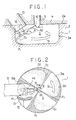
- Fig. 1 is a schematic sectional view of a combustion chamber for internal combustion engines according to the present invention
- Fig. 2 is a plan view of the combustion chamber of Fig. 1
- Fig. 3 is a schematic illustration of rolling streams induced by a protuberance
- Fig. 4 is a fragmentary sectional view of an injection nozzle
- Fig. 5 is a schematic plan view of another embodiment of the invention
- Fig. 6 is a schematic plan view of a conventional spark assisting device for Diesel engines.
- the combustion chamber 3 is formed with a protuberance 12 which is projecting radially inward from the surface of a peripheral wall 3a of the combustion chamber 3.
- the protuberance 12 protrudes radially inward from the peripheral wall surface of the combustion chamber 3 and the sectional configuration of the protuberance 12 transversal to the axis of the piston is like a ball, more specifically the projection 12 is gradually increased in the circumferential direction of the combustion chamber 3 and then gradually reduced after reaching a maximum point.
- the fuel injection nozzle means 5 is located substantially in a center position of the combustion chamber 3.
- the auxiliary nozzle hole 10 of the fuel injection means 5 is opened toward a peripheral wall 3a in the vicinity of the upstream side of the protuberance 12 in the flow direction of the swirl S1.
- the spark plug means 13 ist fixedly fitted in the cylinder head and a notched groove in an upper marginal edge portion of the combustion chamber 3, and its sparking end 13a is disposed in the vicinity of the protuberance of the combustion chamber 3 when the piston is moved to a position in the vicinity of its upper top dead center.
Landscapes
- Engineering & Computer Science (AREA)
- Chemical & Material Sciences (AREA)
- Combustion & Propulsion (AREA)
- Mechanical Engineering (AREA)
- General Engineering & Computer Science (AREA)
- Combustion Methods Of Internal-Combustion Engines (AREA)
- Fuel-Injection Apparatus (AREA)
Claims (13)
- Verbrennungskammer für eine Brennkraftmaschine, insbesondere für die Verbrennung von leichtflüchtigen Kraftstoffen mit niedriger Zetanzahl, mit- einer Verbrennungskammer (3), die durch Aushöhlung des Spitzenbereichs (2) eines Kolbens (1) in axialer Richtung gebildet wird,- einem Höcker (12), der von einer Umfangswandfläche (3a) der Verbrennungskammer (3) radial nach innen vorspringt,- einem Kraftstoff-Einspritzdüsenelement (5), das geeignet ist, um feinzerstäubten Kraftstoff zu einer Umfangswand (3a) in der Nähe und auf der stromaufwärtigen Seite des Höckers (12) in Richtung des Wirbels (S1) und zu anderen Umfangswänden der Verbrennungskammer (3) zu befördern; und- einer Zündkerzeneinrichtung (13), die in der Nähe des Höckers (12) angeordnet ist, um die Zündung des dorthin zugeführten feinzerstäubten Kraftstoffs zu beschleunigen,dadurch gekennzeichnet, daß- die Zündkerzeneinrichtung (13) auf der stromaufwärtigen Seite des Höckers (12) in Richtung des Wirbels (S1) angeordnet ist,- der Höcker (12) derart angeordnet und ausgebildet ist, daß ein Wirbelstrom (R) in Richtung der Drehung des Wirbels (S1) durch den Höcker (12) in der näheren Umgebung der Zündkerzeneinrichtung (13) gebildet wird,- das Kraftstoff-Einspritzdüsenelement (5) mit Düsenhauptlöchern (11) für die Zufuhr des fein zerstäubten Kraftstoffs (F1-F4) in Richtung auf eine Anzahl von gleichmäßig beabstandeten Segmentflächen auf der inneren Umfangswand (3a) der Verbrennungskammer (3) und mit Düsenhilfslöchern (10) für die Zufuhr von fein zerstäubtem Kraftstoff (F5) versehen ist, so daß der Kraftstoff (F1, F1) gerade stromaufwärts von einer Elektrode (13a) oder auf die Elektrode (13a) der Zündkerzeneinrichtung (13) gesprüht wird, so daß der Kraftstoff (F1) und der Kraftstoff aus dem Düsenhilfsloch (10) nicht durch den Wirbel (S1) in der Richtung, in der der Wirbel (S1) fließt, beschleunigt wird, und so daß der Wirbelstrom (R) den Kraftstoff (F1, F5) umgrenzt, um ein verhältnismäßig kraftstoffreiches Gemisch um die Elektrode (13a) der Zündkerzeneinrichtung (13) herum zu erzeugen, während der fein zerstäubte Kraftstoff (F2-F4), der in der Richtung, in der der Wirbel fließt, zu der anderen Umfangswand zugeführt wird, ein verhältnismäßig kraftstoffarmes Gemisch außerhalb des durch den Kraftstoff (F1, F5) geschaffenen Bereichs des verhältnismäßig kraftstoffreichen Gemischs erzeugt,wodurch sich die bei der Verbrennung des verhältnismäßig kraftstoffreichen Gemischs (F1, F5) entstehende Flamme ausbreitet, um das verhältnismäßig kraftstoffarme Gemisch (F2-F4) zu verbrennen.
- Verbrennungskammer nach Anspruch 1, wobei das Einspritzdüsenelement (5) so ausgebildet ist, daß es das Düsenhilfsloch (10) vor den Hauptdüsenlöchern (11) öffnet.
- Verbrennungskammer nach Anspruch 1 oder 2, wobei das Düsenhilfsloch (10) des Kraftstoff-Einspritzdüsenelements (5) einen kleineren offnen Bereich als die Düsenhauptlöcher (11) aufweist.
- Verbrennungskammer nach einem der Ansprüche 1 bis 3, wobei das Kraftstoff-Einspritzdüsenelement (5) fest in einem Zylinderkopf (4) eingebaut und im wesentlichen in einer zentralen Stellung der Verbrennungskammer (3) angeordnet ist.
- Verbrennungskammer nach Anspruch 1, wobei die Zündkerzeneinrichtung (13) fest in dem Zylinderkopf (4) integriert ist.
- Verbrennungskammer nach Anspruch 1, wobei der Höcker (12), der von der Umfangswandfläche (3a) der Verbrennungskammer (3) radial nach innen vorspringt, zum Boden derselben hin verlängert wird.
- Verbrennungskammer nach Anspruch 1 oder 6, wobei der vorspringende Höcker (12) in Umfangsrichtung der Verbrennungskammer (3) allmählich zunimmt und nach Erreichen eines Höchstpunktes dann allmählich abnimmt.
- Verbrennungskammer nach Anspruch 1 oder 6, wobei der Höcker (12) eine im senkrechten Schnitt durch die Kolbenachse (1) glockenähnliche Form hat.
- Verbrennungskammer nach Anspruch 1, wobei die Verbrennungskammer (3) eine im senkrechten Schnitt durch die Kolbenachse (1) runde Form hat.
- Verbrennungskammer nach Anspruch 1, wobei die Verbrennungskammer (3, 103) eine im senkrechten Schnitt durch die Kolbenachse (1) vieleckige Form hat, wobei die Zündkerzeneinrichtung (13) in einem Eckbereich (17) der Vieleckform angeordnet ist, wobei der Höcker (12, 112) auf der in der Richtung des Wirbels stromabwärtigen Seite des Eckbereichs (17) gebildet ist, und wobei das Kraftstoff-Einspritzdüsenelement (5) so ausgebildet ist, daß es fein zerstäubten Kraftstoff zum Eckbereich (17) und zu den Umfangswandbereichen (3a, 103a) der Verbrennungskammer (3, 103) befördert.
- Verbrennungskammer nach Anspruch 10, wobei die vieleckige Verbrennungskammer (3, 103) eine im Querschnitt quadratische Form hat.
- Verbrennungskammer nach Anspruch 10, wobei die vieleckige Verbrennungskammer (3, 103) eine im Querschnitt fünfeckige Form hat.
- Verbrennungskammer nach Anspruch 10, wobei die vieleckige Verbrennungskammer (3, 103) eine im Querschnitt hexagonale Form hat.
Applications Claiming Priority (2)
| Application Number | Priority Date | Filing Date | Title |
|---|---|---|---|
| JP60276024A JPH086590B2 (ja) | 1985-12-10 | 1985-12-10 | 内燃機関の燃焼室 |
| JP276024/85 | 1985-12-10 |
Publications (3)
| Publication Number | Publication Date |
|---|---|
| EP0225637A2 EP0225637A2 (de) | 1987-06-16 |
| EP0225637A3 EP0225637A3 (en) | 1988-09-28 |
| EP0225637B1 true EP0225637B1 (de) | 1991-05-08 |
Family
ID=17563728
Family Applications (1)
| Application Number | Title | Priority Date | Filing Date |
|---|---|---|---|
| EP86117163A Expired - Lifetime EP0225637B1 (de) | 1985-12-10 | 1986-12-09 | Verbrennungskammer für eine Brennkraftmaschine |
Country Status (4)
| Country | Link |
|---|---|
| US (1) | US4733642A (de) |
| EP (1) | EP0225637B1 (de) |
| JP (1) | JPH086590B2 (de) |
| DE (1) | DE3679157D1 (de) |
Families Citing this family (9)
| Publication number | Priority date | Publication date | Assignee | Title |
|---|---|---|---|---|
| JP2500947Y2 (ja) * | 1986-08-27 | 1996-06-12 | 日産ディーゼル工業株式会社 | 火花点火式アルコ―ルエンジンの直接噴射式燃料噴射装置 |
| US5109816A (en) * | 1990-04-27 | 1992-05-05 | Toyota Jidosha Kabushiki Kaisha | Direct fuel injection type spark ignition internal combustion engine |
| JP3073118B2 (ja) * | 1993-04-20 | 2000-08-07 | 株式会社日立製作所 | 筒内噴射式内燃機関 |
| JP3685103B2 (ja) * | 2001-08-02 | 2005-08-17 | 日産自動車株式会社 | 筒内直噴式エンジン |
| JP4767775B2 (ja) * | 2006-07-04 | 2011-09-07 | 本田技研工業株式会社 | 燃料直噴ディーゼルエンジン |
| US9091199B2 (en) * | 2013-02-26 | 2015-07-28 | GM Global Technology Operations LLC | Combustion system for an engine having a swirl inducing combustion chamber |
| EP3376019B1 (de) * | 2015-11-10 | 2023-01-04 | Nissan Motor Co., Ltd. | Verfahren zur steuerung eines verbrennungsmotors |
| US9995203B2 (en) * | 2016-10-27 | 2018-06-12 | Caterpillar Inc. | Piston design for flow re-direction |
| JP6562065B2 (ja) * | 2017-12-15 | 2019-08-21 | マツダ株式会社 | 圧縮着火式エンジンの制御装置 |
Family Cites Families (15)
| Publication number | Priority date | Publication date | Assignee | Title |
|---|---|---|---|---|
| US2046263A (en) * | 1929-10-17 | 1936-06-30 | Hesselman Motor Corp Ltd | Internal combustion engine |
| US1988754A (en) * | 1932-09-29 | 1935-01-22 | Superior Engine Company | Internal combustion engine |
| US2457652A (en) * | 1946-03-15 | 1948-12-28 | Waukesha Motor Co | Internal-combustion engine |
| DE1211435B (de) * | 1957-07-06 | 1966-02-24 | Maschf Augsburg Nuernberg Ag | Luftverdichtende, selbstzuendende Brennkraftmaschine |
| GB1204947A (en) * | 1967-06-24 | 1970-09-09 | Daimler Benz Ag | Internal combustion engine with fuel injection |
| CH478343A (de) * | 1967-09-22 | 1969-09-15 | Maschf Augsburg Nuernberg Ag | Fremdgezündete, luftverdichtende Einspritzbrennkraftmaschine |
| DE1576020A1 (de) * | 1967-09-22 | 1970-04-02 | Maschf Augsburg Nuernberg Ag | Fremdgezuendete,luftverdichtende Einspritzbrennkraftmaschine |
| CA992415A (en) * | 1972-08-25 | 1976-07-06 | Isuzu Motors Limited | Construction arrangement of combustion chamber for use in direct fuel injection type diesel engines |
| JPS5142248B2 (de) * | 1972-09-18 | 1976-11-15 | ||
| DE2837606A1 (de) * | 1978-08-29 | 1980-03-06 | Daimler Benz Ag | Mehrstrahliges einspritzventil |
| JPS58178419U (ja) * | 1982-05-26 | 1983-11-29 | 株式会社小松製作所 | デイ−ゼルエンジンのスパ−クアシスト装置 |
| JPS5954728A (ja) * | 1982-09-21 | 1984-03-29 | Toyota Central Res & Dev Lab Inc | 内燃機関の乱れ生成方法及びその内燃機関 |
| JPS5981775U (ja) * | 1982-11-22 | 1984-06-02 | マツダ株式会社 | 直接噴射式デイ−ゼルエンジン |
| JPS59192823A (ja) * | 1983-04-16 | 1984-11-01 | Toyota Central Res & Dev Lab Inc | 筒内燃料噴射式内燃機関 |
| JPS59226226A (ja) * | 1983-06-07 | 1984-12-19 | Toyota Motor Corp | 筒内燃料噴射式火花点火内燃機関 |
-
1985
- 1985-12-10 JP JP60276024A patent/JPH086590B2/ja not_active Expired - Fee Related
-
1986
- 1986-12-09 EP EP86117163A patent/EP0225637B1/de not_active Expired - Lifetime
- 1986-12-09 DE DE8686117163T patent/DE3679157D1/de not_active Expired - Fee Related
- 1986-12-10 US US06/939,989 patent/US4733642A/en not_active Expired - Fee Related
Also Published As
| Publication number | Publication date |
|---|---|
| EP0225637A3 (en) | 1988-09-28 |
| DE3679157D1 (de) | 1991-06-13 |
| JPH086590B2 (ja) | 1996-01-24 |
| JPS62135613A (ja) | 1987-06-18 |
| EP0225637A2 (de) | 1987-06-16 |
| US4733642A (en) | 1988-03-29 |
Similar Documents
| Publication | Publication Date | Title |
|---|---|---|
| JP2590170B2 (ja) | 燃料燃焼システム用の火炎培養増殖装置 | |
| EP0249699B1 (de) | Brennkraftmaschine mit Brennstoffeinspritzung | |
| EP0227935B1 (de) | Brennkammer für Brennkraftmaschine | |
| US4125094A (en) | Internal combustion engine with an auxiliary combustion chamber | |
| EP0225637B1 (de) | Verbrennungskammer für eine Brennkraftmaschine | |
| EP0224879B1 (de) | Brennkammer für Brennkraftmaschine | |
| EP0205000B1 (de) | Brennkammer für Brennkraftmaschine | |
| US4733643A (en) | Combustion chamber arrangement for an internal combustion engine | |
| JPS62214216A (ja) | 内燃機関の燃焼室 | |
| JPH04228821A (ja) | 直接噴射式ディーゼル機関の燃焼室 | |
| JPS62139919A (ja) | 内燃機関の燃焼室 | |
| JPH063134B2 (ja) | スパークアシストデイーゼル機関の燃焼室 | |
| JP2521902B2 (ja) | 内燃機関の燃焼室 | |
| JP2521914B2 (ja) | 内燃機関 | |
| JPH0755295Y2 (ja) | 内燃機関の燃焼室 | |
| JPH059617B2 (de) | ||
| JPH063135B2 (ja) | スパークアシストデイーゼル機関の燃焼室 | |
| JPH04187815A (ja) | 筒内直接噴射式火花点火機関 | |
| JPH01116220A (ja) | スパークアシストディーゼル機関 | |
| JPH063137B2 (ja) | 内燃機関の燃焼室 | |
| JPH04330327A (ja) | 直接噴射式ディ−ゼル機関の燃焼室 | |
| JPS6368716A (ja) | 直噴式デイ−ゼル機関 | |
| JPS62255526A (ja) | 内燃機関の燃焼室 | |
| JPS62276214A (ja) | 内燃機関の燃焼室 | |
| JPS6368717A (ja) | 直噴式デイ−ゼル機関 |
Legal Events
| Date | Code | Title | Description |
|---|---|---|---|
| PUAI | Public reference made under article 153(3) epc to a published international application that has entered the european phase |
Free format text: ORIGINAL CODE: 0009012 |
|
| AK | Designated contracting states |
Kind code of ref document: A2 Designated state(s): DE FR GB |
|
| PUAL | Search report despatched |
Free format text: ORIGINAL CODE: 0009013 |
|
| RHK1 | Main classification (correction) |
Ipc: F02B 23/10 |
|
| AK | Designated contracting states |
Kind code of ref document: A3 Designated state(s): DE FR GB |
|
| 17P | Request for examination filed |
Effective date: 19890210 |
|
| 17Q | First examination report despatched |
Effective date: 19890619 |
|
| GRAA | (expected) grant |
Free format text: ORIGINAL CODE: 0009210 |
|
| AK | Designated contracting states |
Kind code of ref document: B1 Designated state(s): DE FR GB |
|
| REF | Corresponds to: |
Ref document number: 3679157 Country of ref document: DE Date of ref document: 19910613 |
|
| ET | Fr: translation filed | ||
| PLBE | No opposition filed within time limit |
Free format text: ORIGINAL CODE: 0009261 |
|
| STAA | Information on the status of an ep patent application or granted ep patent |
Free format text: STATUS: NO OPPOSITION FILED WITHIN TIME LIMIT |
|
| 26N | No opposition filed | ||
| PGFP | Annual fee paid to national office [announced via postgrant information from national office to epo] |
Ref country code: FR Payment date: 20001113 Year of fee payment: 15 |
|
| PGFP | Annual fee paid to national office [announced via postgrant information from national office to epo] |
Ref country code: GB Payment date: 20001120 Year of fee payment: 15 |
|
| PGFP | Annual fee paid to national office [announced via postgrant information from national office to epo] |
Ref country code: DE Payment date: 20001122 Year of fee payment: 15 |
|
| PG25 | Lapsed in a contracting state [announced via postgrant information from national office to epo] |
Ref country code: GB Free format text: LAPSE BECAUSE OF NON-PAYMENT OF DUE FEES Effective date: 20011209 |
|
| REG | Reference to a national code |
Ref country code: GB Ref legal event code: IF02 |
|
| PG25 | Lapsed in a contracting state [announced via postgrant information from national office to epo] |
Ref country code: DE Free format text: LAPSE BECAUSE OF NON-PAYMENT OF DUE FEES Effective date: 20020702 |
|
| GBPC | Gb: european patent ceased through non-payment of renewal fee |
Effective date: 20011209 |
|
| PG25 | Lapsed in a contracting state [announced via postgrant information from national office to epo] |
Ref country code: FR Free format text: LAPSE BECAUSE OF NON-PAYMENT OF DUE FEES Effective date: 20020830 |
|
| REG | Reference to a national code |
Ref country code: FR Ref legal event code: ST |