EP0225679A1 - Elektrochemische Zelle - Google Patents
Elektrochemische Zelle Download PDFInfo
- Publication number
- EP0225679A1 EP0225679A1 EP86302458A EP86302458A EP0225679A1 EP 0225679 A1 EP0225679 A1 EP 0225679A1 EP 86302458 A EP86302458 A EP 86302458A EP 86302458 A EP86302458 A EP 86302458A EP 0225679 A1 EP0225679 A1 EP 0225679A1
- Authority
- EP
- European Patent Office
- Prior art keywords
- cathode
- electrochemical cell
- terminal pin
- cell according
- housing
- Prior art date
- Legal status (The legal status is an assumption and is not a legal conclusion. Google has not performed a legal analysis and makes no representation as to the accuracy of the status listed.)
- Granted
Links
Images
Classifications
-
- H—ELECTRICITY
- H01—ELECTRIC ELEMENTS
- H01M—PROCESSES OR MEANS, e.g. BATTERIES, FOR THE DIRECT CONVERSION OF CHEMICAL ENERGY INTO ELECTRICAL ENERGY
- H01M6/00—Primary cells; Manufacture thereof
- H01M6/14—Cells with non-aqueous electrolyte
- H01M6/16—Cells with non-aqueous electrolyte with organic electrolyte
-
- H—ELECTRICITY
- H01—ELECTRIC ELEMENTS
- H01M—PROCESSES OR MEANS, e.g. BATTERIES, FOR THE DIRECT CONVERSION OF CHEMICAL ENERGY INTO ELECTRICAL ENERGY
- H01M50/00—Constructional details or processes of manufacture of the non-active parts of electrochemical cells other than fuel cells, e.g. hybrid cells
- H01M50/10—Primary casings; Jackets or wrappings
- H01M50/172—Arrangements of electric connectors penetrating the casing
- H01M50/174—Arrangements of electric connectors penetrating the casing adapted for the shape of the cells
-
- H—ELECTRICITY
- H01—ELECTRIC ELEMENTS
- H01M—PROCESSES OR MEANS, e.g. BATTERIES, FOR THE DIRECT CONVERSION OF CHEMICAL ENERGY INTO ELECTRICAL ENERGY
- H01M50/00—Constructional details or processes of manufacture of the non-active parts of electrochemical cells other than fuel cells, e.g. hybrid cells
- H01M50/50—Current conducting connections for cells or batteries
- H01M50/543—Terminals
- H01M50/562—Terminals characterised by the material
-
- H—ELECTRICITY
- H01—ELECTRIC ELEMENTS
- H01M—PROCESSES OR MEANS, e.g. BATTERIES, FOR THE DIRECT CONVERSION OF CHEMICAL ENERGY INTO ELECTRICAL ENERGY
- H01M50/00—Constructional details or processes of manufacture of the non-active parts of electrochemical cells other than fuel cells, e.g. hybrid cells
- H01M50/50—Current conducting connections for cells or batteries
- H01M50/543—Terminals
- H01M50/564—Terminals characterised by their manufacturing process
- H01M50/566—Terminals characterised by their manufacturing process by welding, soldering or brazing
-
- Y—GENERAL TAGGING OF NEW TECHNOLOGICAL DEVELOPMENTS; GENERAL TAGGING OF CROSS-SECTIONAL TECHNOLOGIES SPANNING OVER SEVERAL SECTIONS OF THE IPC; TECHNICAL SUBJECTS COVERED BY FORMER USPC CROSS-REFERENCE ART COLLECTIONS [XRACs] AND DIGESTS
- Y02—TECHNOLOGIES OR APPLICATIONS FOR MITIGATION OR ADAPTATION AGAINST CLIMATE CHANGE
- Y02E—REDUCTION OF GREENHOUSE GAS [GHG] EMISSIONS, RELATED TO ENERGY GENERATION, TRANSMISSION OR DISTRIBUTION
- Y02E60/00—Enabling technologies; Technologies with a potential or indirect contribution to GHG emissions mitigation
- Y02E60/10—Energy storage using batteries
Definitions
- the present invention relates to electrochemical cells. It particularly relates to cells utilizing lithium as the anode material.
- Lithium is well suited for use in electrochemical cells because of its high voltage capability and high output density.
- miniature cells such as a button cell, a coin cell or other so called “flat cells” a ferrous metal such as stainless steel is commonly used for the container. This is because stainless steel is generally corrosion resistant, is easily formed or machined into a miniature container and is electrically conductive so the container itself can form one terminal of the cell.
- the second cell terminal is a pin which extends through a hermetically sealed opening in the cell wall.
- Miniature cells of this type are often constructed so that the cell components such as the anode, cathode and electrolyte are arranged in substantially flat superimposed layers.
- the anode or negative electrode describes the cell material which is oxidized and the cathode or positive electrode includes the cell material which is reduced during cell discharge.
- a typical 1.5 to 4 volt miniature cell of this type which measures less than 1.27 cm (0.5 inch) in diameter and less than about 0.51 cm (about 0.2 inch) thick has as its anode, a lithium metal wafer about 0.05 cm (about 0.02 inch) thick.
- the cathode of the cell would vary in thickness depending upon its type and density. For example, a typical cathode which comprises a pressed powder mixture of a conductor, a binder, and an active cathode material such as manganese dioxide (MnO2), would be about 0.15 cm (about 0.06 inch) thick.
- the cathode and anode are separated within the cell by a separator member which also serves as an electrolyte carrier. Either the anode or cathode is laid flat against the bottom of the container (usually made of a ferrous metal such as stainless steel) while the other is connected to the terminal pin extending through a hermetically sealed opening of the container wall.
- the opening about the pin is sealed by a fused glass-to-metal (GTM) seal.
- GTM fused glass-to-metal
- the glass member not only hermetically seals the opening but also electronically insulates the pin from the adjacent ferrous metal container wall.
- the GTM seal has been a problem area in cell construction, particularly in high voltage cell systems which utilize lithium as the negative electrode. For example, it has been found that during storage, a conductive corrosive deposit grows from the anode across the surface of the GTM toward the cathode until eventually the glass seal is bridged and the cell shorts.
- the shelf life of the cell is prolonged regardless of the composition of the glass in the GTM seal or the make-up of the seal. This is accomplished by controlling both the materials of construction of cell components and the arrangement of these components within the cell.
- the invention is an improved cell construction for hermetically sealed cells of the type having a terminal pin extending through a wall of the cell housing and electrically insulated from the wall preferably by a GTM seal. While the invention is applicable to a variety of cell configurations and voltages, it is preferred in high voltage cells having an open circuit voltage in the range of about 2.0 volts and above.
- an electrochemical cell comprising:
- a GTM seal is used to secure the terminal pin in the opening and to electronically isolate the terminal pin from the housing.
- glass includes ceramics and various types of glasses commonly used in GTM seals, such as borosilicate glass, or the composite glass seals of the type described in US-A- 4 308 323.
- the lithium metal anode is electronically connected to a ferrous metal housing so that the housing itself becomes the anodic terminal of the cell.
- the cathode is electronically connected to a terminal pin so that the pin is the cathodic terminal of the cell.
- a conductive cathode collector is provided which contacts a portion of the cathode surface. The cathode collector is then electronically connected to the terminal pin.
- any cell component electronically connected to the cathode preferably should be made of a non-ferrous metal. This is because it has been found that the conductive corrosive deposit on the surface of the GTM seal is drastically reduced if both the terminal pin and the collector grid in contact with the active cathode are made of a non-ferrous metal.
- any suitable alkali metal including sodium, an alkali metal alloy, an alkaline earth metal or an alkaline earth metal alloy can be used as the anode material.
- Non-ferrous metals suitable for use as the terminal pin and cathode collector include molybdenum, tantalum, titanium and tungsten.
- Cathodes for use in the present invention are well known in the art and include such solid and liquid active cathode materials as MnO2, TiS2, FeS2, Sb2S3, MoS3, SO2, SOCl2, SO2Cl2, C2F, CF x (where x is above 0.0 to about 1.2) or mixtures thereof.
- Electrolytes for use in the present invention are well known and can be either in solid or liquid form.
- a solid electrolyte can be used with a liquid or solid active cathode material and a liquid electrolyte used with a solid active cathode material.
- Glasses suitable for the GTM seal about the terminal pin also are well known in the art. These include, for example, the glass compositions described in US-A- 4 308 323, US-A- 4 168 351, and conventional borosilicate glass.
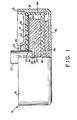
- Figure 1 shows an electrochemical cell in accordance with the present invention, generally indicated at 10.
- the cell includes a housing which consists of an open-ended container 12 and a cover 14 for the open end, both formed of a ferrous metal such as stainless steel.
- the container has a bottom wall 16, and an upstanding side wall 18.
- the open end of the container is closed by the cover 14 which can be considered a top wall of the container because it is welded or otherwise hermetically sealed about its outer periphery 15 to the container side wall 18.
- Cover 14 has an opening 20 to accommodate the passage of a cylindrical terminal pin 22 through the cover 14 and into the container.
- terminal pin 22 is of a non-ferrous metal such as molybdenum.
- a glass bead 24 is disposed within the opening 20 and is fused to both the terminal pin 22 and to the adjacent portion of cover 14 which defines opening 20. In this fashion the fused glass bead 24 secures the terminal pin within the opening, provides a hermetic seal means between terminal pin 22 and cover 14 and electrically insulates the terminal pin from the container 12.
- the electrochemical cell system within container 12 includes a lithium anode 26.
- the anode is in the form of a relatively thin wafer of lithium having one of its flat surfaces disposed against the inner surface of the container bottom wall 16. This electronically connects the anode to the container 12 thereby rendering it the anodic terminal of the cell.
- a cathode assembly 28 including a cathode 30 and a cathode collector 32.
- the preferred cathode is conventional and consists of a pressed powder mixture of a conductor, a binder and an active cathode material such as MnO2.
- the cathode collector 32 preferably is a disc made of a non-ferrous metal such as molybdenum.
- the cathode collector in the form of a disc provides support for the cathode mixture which is pressed against the disc so that a face 34 of the cathode contacts the cathode collector and electronically connects the cathode and cathode collector.
- the cathode collector 32 in turn is connected to terminal pin 22 by any suitable mechanical and electrical connection which electronically connects the cathode collector 32 and the terminal pin 22 thereby rendering the terminal pin 22 the cathodic terminal of the cell.
- cathode face 34 has a portion of its surface defining a recess 38 and the lower end 36 of the cylindrical terminal pin 22, extended through an opening 33 in the cathode collector, is received in the recess.
- the recess is large enough so that the surface which defines the recess is spaced from the terminal pin lower end 36 to provide clearance around the end portion of the terminal pin received in the recess. This clearance insures that the fused glass bead 24 is not subjected to stress when the cell is assembled.
- cover 14 together with terminal pin 22 and GTM seal formed by glass bead 24 is preassembled and then later attached as a unit to container 12.
- the separator Disposed between the anode 26 and the active cathode 30 is a separator 40.
- the separator is conventional and is made from a non-conductive ion permeable material.
- the separator is a felted glass fiber fabric impregnated with an electrolyte solution.
- Completing the cell structure is an electronically insulating layer 42 which extends between the cathode collector and cover 14.
- the insulating layer includes a depending peripheral portion 44 which extends down to the separator 40 so as to maintain the cathode electronically insulated from the cell housing.
- the cell housing was a stainless steel container measuring 1.151 cm (0.453 inch) in diameter by 0.371 cm (0.146 inch) high with a wall thickness of 0.025 cm (0.010 inch).
- the separator was a felted glass fiber fabric impregnated with a 50/50 mixture of propylene carbonate and dimethoxyethane containing one molar of LiCF3SO3 as the liquid electrolyte.
- the cathode utilized MnO2 as the active cathode material and was 0.152 cm (0.60 inch) thick and about 0.914 cm (about 0.360 inch) in diameter. Both the cathode collector and terminal pin were made of molybdenum.
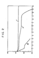
- the average open circuit voltage of five cells was 3.42 volts. These cells were then held at a temperature of 90°C and the open circuit voltage was measured periodically. The result of this test is illustrated by curve I in Figure 2. Curve I shows that after a period of fourteen (14) weeks the average open circuit voltage of the five cells was 3.32 volts. Thus the cells, on average, were still at about 97% of their initial open circuit voltage. Moreover at the end of twenty-nine weeks, the cells, on average, were still displaying an open circuit voltage of about 3.32 volts.
- a control consisting of a second group of cells was fabricated identical to the cells of Example 1 except that a stainless stell cathode collector was used instead of a molybdenum cathode collector. As fabricated, five cells had, on the average, an open circuit voltage of 3.42 volts. These cells were also held at a temperature of 90°C and tested periodically.
- a second control consisting of a third group of cells, was fabricated identical to the cells of Example 2 except that the relative positions of the anode and cathode were reversed.
- the cathode contacted the bottom surface of the stainless steel container thereby rendering the cell container the cathodic terminal of the cell.
- the lithium metal anode through its contact with the anode collector, electronically contacted the terminal pin thereby rendering the terminal pin the anodic terminal of the cell.
- the terminal pin was made of molybdenum and the collector (in contact with the lithium anode) was of stainless steel.
- the cells, constructed in this fashion, had on the average an open circuit voltage of 3.41 volts. As shown by curve III, after only four weeks at a temperature of 90°C, the open circuit voltage of these cells had dropped, on the average, to only 2.62 volts or about 77% of the initial open circuit voltage.
- the present invention provides lithium anode cells with a prolonged shelf life and enhanced long-term open circuit voltage characteristics.
Landscapes
- Chemical & Material Sciences (AREA)
- Chemical Kinetics & Catalysis (AREA)
- Electrochemistry (AREA)
- General Chemical & Material Sciences (AREA)
- Engineering & Computer Science (AREA)
- Manufacturing & Machinery (AREA)
- Primary Cells (AREA)
- Connection Of Batteries Or Terminals (AREA)
- Cell Electrode Carriers And Collectors (AREA)
Applications Claiming Priority (2)
| Application Number | Priority Date | Filing Date | Title |
|---|---|---|---|
| US06/794,541 US4609598A (en) | 1985-11-04 | 1985-11-04 | Electrochemical cell |
| US794541 | 1985-11-04 |
Publications (2)
| Publication Number | Publication Date |
|---|---|
| EP0225679A1 true EP0225679A1 (de) | 1987-06-16 |
| EP0225679B1 EP0225679B1 (de) | 1990-05-09 |
Family
ID=25162936
Family Applications (1)
| Application Number | Title | Priority Date | Filing Date |
|---|---|---|---|
| EP86302458A Expired - Lifetime EP0225679B1 (de) | 1985-11-04 | 1986-04-03 | Elektrochemische Zelle |
Country Status (4)
| Country | Link |
|---|---|
| US (1) | US4609598A (de) |
| EP (1) | EP0225679B1 (de) |
| JP (1) | JPS62108461A (de) |
| DE (1) | DE3671135D1 (de) |
Cited By (2)
| Publication number | Priority date | Publication date | Assignee | Title |
|---|---|---|---|---|
| FR2601820A1 (fr) * | 1986-07-18 | 1988-01-22 | Eveready Battery Inc | Pile electrochimique close, comportant un ensemble borne-plaque collectrice perfectionne pour en faciliter la ventilation |
| EP0924779A1 (de) * | 1997-12-19 | 1999-06-23 | Sony Corporation | Sekundärbatterie mit nichtwässrigem Elektrolyten |
Families Citing this family (16)
| Publication number | Priority date | Publication date | Assignee | Title |
|---|---|---|---|---|
| US5004656A (en) * | 1988-08-29 | 1991-04-02 | Hitachi Maxell, Ltd. | Flat type sealed battery with hermetic sealing structure |
| US4997732A (en) * | 1989-03-30 | 1991-03-05 | Mhb Joint Venture | Battery in a vacuum sealed enveloping material and a process for making the same |
| US5104755A (en) * | 1989-06-15 | 1992-04-14 | Medtronic, Inc. | Glass-metal seals |
| US5306581A (en) * | 1989-06-15 | 1994-04-26 | Medtronic, Inc. | Battery with weldable feedthrough |
| US5162172A (en) * | 1990-12-14 | 1992-11-10 | Arch Development Corporation | Bipolar battery |
| US5716729A (en) * | 1996-04-26 | 1998-02-10 | Medtronic, Inc. | Electrochemical cell |
| US6855456B2 (en) | 2001-10-30 | 2005-02-15 | Medtronic, Inc. | Titanium alloy-pin battery feedthrough for an implantable medical device |
| JP2004228086A (ja) | 2003-01-17 | 2004-08-12 | Wilson Greatbatch Technologies Inc | ハーメチックシールされたボタン電池 |
| US8377586B2 (en) | 2005-10-05 | 2013-02-19 | California Institute Of Technology | Fluoride ion electrochemical cell |
| US20070218364A1 (en) * | 2005-10-05 | 2007-09-20 | Whitacre Jay F | Low temperature electrochemical cell |
| US8232007B2 (en) * | 2005-10-05 | 2012-07-31 | California Institute Of Technology | Electrochemistry of carbon subfluorides |
| US7749651B2 (en) * | 2005-11-28 | 2010-07-06 | Greatbatch Ltd. | Terminal connector for connecting an electrochemical cell to a medical device |
| JP5011732B2 (ja) * | 2006-01-20 | 2012-08-29 | ソニー株式会社 | 電池 |
| US20090111021A1 (en) * | 2007-03-14 | 2009-04-30 | Rachid Yazami | High discharge rate batteries |
| US11626638B2 (en) * | 2019-03-05 | 2023-04-11 | Eaglepicher Technologies, Llc | Batteries and methods of using and making the same |
| US20250199073A1 (en) * | 2023-12-15 | 2025-06-19 | MilesAhead Energy, LLC | Solid state battery and a device and method of testing |
Citations (2)
| Publication number | Priority date | Publication date | Assignee | Title |
|---|---|---|---|---|
| GB2014354A (en) * | 1978-02-10 | 1979-08-22 | Mallory & Co Inc P R | Stabilized glass-to-metal seals in lithium cells |
| US4182028A (en) * | 1976-08-02 | 1980-01-08 | Gte Laboratories Inc. | Hermetically sealed button-type electrochemical cell and method for making same |
Family Cites Families (6)
| Publication number | Priority date | Publication date | Assignee | Title |
|---|---|---|---|---|
| US4233372A (en) * | 1979-05-09 | 1980-11-11 | P. R. Mallory & Co. Inc. | Hermetic seal for electrochemical cell |
| US4556613A (en) * | 1979-07-03 | 1985-12-03 | Duracell Inc. | Resistant glass in glass-metal seal and cell terminal structure for lithium electrochemical cells |
| EP0035074A3 (de) * | 1980-02-04 | 1981-10-21 | Power Conversion, Inc. | Korrosionsbeständige Poldurchführung für galvanische Zellen |
| US4308323A (en) * | 1980-11-10 | 1981-12-29 | Emerson Electric Co. | Battery seal |
| JPS59228357A (ja) * | 1983-06-09 | 1984-12-21 | Japan Storage Battery Co Ltd | 密閉形リチウム電池 |
| JPS60175373A (ja) * | 1984-02-20 | 1985-09-09 | Hitachi Maxell Ltd | リチウム電池 |
-
1985
- 1985-11-04 US US06/794,541 patent/US4609598A/en not_active Expired - Lifetime
-
1986
- 1986-04-03 EP EP86302458A patent/EP0225679B1/de not_active Expired - Lifetime
- 1986-04-03 DE DE8686302458T patent/DE3671135D1/de not_active Expired - Lifetime
- 1986-05-28 JP JP61121414A patent/JPS62108461A/ja active Pending
Patent Citations (2)
| Publication number | Priority date | Publication date | Assignee | Title |
|---|---|---|---|---|
| US4182028A (en) * | 1976-08-02 | 1980-01-08 | Gte Laboratories Inc. | Hermetically sealed button-type electrochemical cell and method for making same |
| GB2014354A (en) * | 1978-02-10 | 1979-08-22 | Mallory & Co Inc P R | Stabilized glass-to-metal seals in lithium cells |
Non-Patent Citations (2)
| Title |
|---|
| PATENTS ABSTRACTS OF JAPAN, vol. 7, mo. 144 (E-183)[1289], 23th June 1983; & JP-A-58 057 257 (DAINA SEIKOSHA K.K.) 05-04-1983 * |
| PATENTS ABSTRACTS OF JAPAN, vol. 8, no. 135 (E-252)[1572], 22nd June 1984; & JP-A-59 046 766 (TOSHIBA DENCHI K.K.) 16-03-1984 * |
Cited By (3)
| Publication number | Priority date | Publication date | Assignee | Title |
|---|---|---|---|---|
| FR2601820A1 (fr) * | 1986-07-18 | 1988-01-22 | Eveready Battery Inc | Pile electrochimique close, comportant un ensemble borne-plaque collectrice perfectionne pour en faciliter la ventilation |
| EP0924779A1 (de) * | 1997-12-19 | 1999-06-23 | Sony Corporation | Sekundärbatterie mit nichtwässrigem Elektrolyten |
| US6572998B2 (en) | 1997-12-19 | 2003-06-03 | Sony Corporation | Non-aqueous electrolyte secondary battery |
Also Published As
| Publication number | Publication date |
|---|---|
| JPS62108461A (ja) | 1987-05-19 |
| US4609598A (en) | 1986-09-02 |
| EP0225679B1 (de) | 1990-05-09 |
| DE3671135D1 (de) | 1990-06-13 |
Similar Documents
| Publication | Publication Date | Title |
|---|---|---|
| US4609598A (en) | Electrochemical cell | |
| US4683516A (en) | Extended life capacitor and method | |
| CA1187548A (en) | Electrochemical cell | |
| EP0441589B1 (de) | Hohe Energiedichte aufweisende Lithiumzelle mit nicht-wässrigem Elektrolyt, die über einen weiten Temeperaturbereich einsatzbereit ist | |
| EP0290764B1 (de) | Bipolare zylindrische Batterie | |
| CA1120536A (en) | Stabilized glass-to-metal seals in lithium cell environments | |
| US5411818A (en) | Perimeter seal on bipolar walls for use in high temperature molten electrolyte batteries | |
| US5658688A (en) | Lithium-silver oxide battery and lithium-mercuric oxide battery | |
| US4287273A (en) | Plural cell battery structure | |
| US5234778A (en) | Electrochemical cell | |
| US4293622A (en) | Step cell | |
| GB2083686A (en) | Electrochemical storage cell | |
| US5639578A (en) | Current collectors for alkaline cells | |
| US4770956A (en) | Electrochemical storage cell | |
| US4971868A (en) | Hermetically sealed nonaqueous cell with positive terminal pin and perchlorate electrolyte | |
| US4438184A (en) | Sealed passage for a negative terminal through a metal wall, and electric cell using said sealed passage | |
| EP0067278B1 (de) | Aussenseitig beschichtete hermetische Verschlüsse zur Verwendung bei elektrochemischen Zellen | |
| EP0145931B1 (de) | Elektrodenstruktur für elektrochemische Zelle | |
| JP2752361B2 (ja) | 正極端子ピンと過塩素酸塩電解質を有する密閉された非水性電池 | |
| US5389457A (en) | Gas filled collapsible member within anode to accommodate expansion of anode | |
| EP0118657A1 (de) | Nichtwässrige elektrochemische Zelle | |
| US4410608A (en) | Electrochemical cell | |
| US4897323A (en) | High temperature dischargeable galvanic primary element having alkaline electrolyte | |
| EP1048091B1 (de) | Elektrochemische zelle mit mehreren anodenkammern | |
| US3082285A (en) | Leak resistant dry cell |
Legal Events
| Date | Code | Title | Description |
|---|---|---|---|
| PUAI | Public reference made under article 153(3) epc to a published international application that has entered the european phase |
Free format text: ORIGINAL CODE: 0009012 |
|
| AK | Designated contracting states |
Kind code of ref document: A1 Designated state(s): DE FR GB |
|
| 17P | Request for examination filed |
Effective date: 19871209 |
|
| RAP1 | Party data changed (applicant data changed or rights of an application transferred) |
Owner name: EVEREADY BATTERY COMPANY, INC. |
|
| 17Q | First examination report despatched |
Effective date: 19881018 |
|
| GRAA | (expected) grant |
Free format text: ORIGINAL CODE: 0009210 |
|
| AK | Designated contracting states |
Kind code of ref document: B1 Designated state(s): DE FR GB |
|
| ET | Fr: translation filed | ||
| REF | Corresponds to: |
Ref document number: 3671135 Country of ref document: DE Date of ref document: 19900613 |
|
| PLBE | No opposition filed within time limit |
Free format text: ORIGINAL CODE: 0009261 |
|
| STAA | Information on the status of an ep patent application or granted ep patent |
Free format text: STATUS: NO OPPOSITION FILED WITHIN TIME LIMIT |
|
| PGFP | Annual fee paid to national office [announced via postgrant information from national office to epo] |
Ref country code: DE Payment date: 19910325 Year of fee payment: 6 |
|
| 26N | No opposition filed | ||
| PG25 | Lapsed in a contracting state [announced via postgrant information from national office to epo] |
Ref country code: DE Effective date: 19930101 |
|
| PGFP | Annual fee paid to national office [announced via postgrant information from national office to epo] |
Ref country code: FR Payment date: 20000317 Year of fee payment: 15 |
|
| PGFP | Annual fee paid to national office [announced via postgrant information from national office to epo] |
Ref country code: GB Payment date: 20000321 Year of fee payment: 15 |
|
| PG25 | Lapsed in a contracting state [announced via postgrant information from national office to epo] |
Ref country code: GB Free format text: LAPSE BECAUSE OF NON-PAYMENT OF DUE FEES Effective date: 20010403 |
|
| PG25 | Lapsed in a contracting state [announced via postgrant information from national office to epo] |
Ref country code: FR Free format text: THE PATENT HAS BEEN ANNULLED BY A DECISION OF A NATIONAL AUTHORITY Effective date: 20010430 |
|
| GBPC | Gb: european patent ceased through non-payment of renewal fee |
Effective date: 20010403 |
|
| REG | Reference to a national code |
Ref country code: FR Ref legal event code: ST |