EP0225855B1 - Porte de véhicule, en particulier pour voitures de chemin de fer ou de métro - Google Patents
Porte de véhicule, en particulier pour voitures de chemin de fer ou de métro Download PDFInfo
- Publication number
- EP0225855B1 EP0225855B1 EP86830186A EP86830186A EP0225855B1 EP 0225855 B1 EP0225855 B1 EP 0225855B1 EP 86830186 A EP86830186 A EP 86830186A EP 86830186 A EP86830186 A EP 86830186A EP 0225855 B1 EP0225855 B1 EP 0225855B1
- Authority
- EP
- European Patent Office
- Prior art keywords
- panel
- frame
- shaft
- door
- panels
- Prior art date
- Legal status (The legal status is an assumption and is not a legal conclusion. Google has not performed a legal analysis and makes no representation as to the accuracy of the status listed.)
- Expired - Lifetime
Links
Images


Classifications
-
- B—PERFORMING OPERATIONS; TRANSPORTING
- B61—RAILWAYS
- B61D—BODY DETAILS OR KINDS OF RAILWAY VEHICLES
- B61D19/00—Door arrangements specially adapted for rail vehicles
- B61D19/003—Door arrangements specially adapted for rail vehicles characterised by the movements of the door
- B61D19/009—Door arrangements specially adapted for rail vehicles characterised by the movements of the door both sliding and plugging, (e.g. for refrigerator cars)
-
- E—FIXED CONSTRUCTIONS
- E05—LOCKS; KEYS; WINDOW OR DOOR FITTINGS; SAFES
- E05D—HINGES OR SUSPENSION DEVICES FOR DOORS, WINDOWS OR WINGS
- E05D15/00—Suspension arrangements for wings
- E05D15/06—Suspension arrangements for wings for wings sliding horizontally more or less in their own plane
- E05D15/10—Suspension arrangements for wings for wings sliding horizontally more or less in their own plane movable out of one plane into a second parallel plane
- E05D15/1065—Suspension arrangements for wings for wings sliding horizontally more or less in their own plane movable out of one plane into a second parallel plane with transversely moving track
- E05D15/1068—Suspension arrangements for wings for wings sliding horizontally more or less in their own plane movable out of one plane into a second parallel plane with transversely moving track specially adapted for use in railway-cars or mass transit vehicles
-
- E—FIXED CONSTRUCTIONS
- E05—LOCKS; KEYS; WINDOW OR DOOR FITTINGS; SAFES
- E05F—DEVICES FOR MOVING WINGS INTO OPEN OR CLOSED POSITION; CHECKS FOR WINGS; WING FITTINGS NOT OTHERWISE PROVIDED FOR, CONCERNED WITH THE FUNCTIONING OF THE WING
- E05F15/00—Power-operated mechanisms for wings
- E05F15/50—Power-operated mechanisms for wings using fluid-pressure actuators
- E05F15/56—Power-operated mechanisms for wings using fluid-pressure actuators for horizontally-sliding wings
- E05F15/565—Power-operated mechanisms for wings using fluid-pressure actuators for horizontally-sliding wings for railway-cars
-
- E—FIXED CONSTRUCTIONS
- E05—LOCKS; KEYS; WINDOW OR DOOR FITTINGS; SAFES
- E05D—HINGES OR SUSPENSION DEVICES FOR DOORS, WINDOWS OR WINGS
- E05D15/00—Suspension arrangements for wings
- E05D15/06—Suspension arrangements for wings for wings sliding horizontally more or less in their own plane
- E05D15/10—Suspension arrangements for wings for wings sliding horizontally more or less in their own plane movable out of one plane into a second parallel plane
- E05D15/1065—Suspension arrangements for wings for wings sliding horizontally more or less in their own plane movable out of one plane into a second parallel plane with transversely moving track
- E05D2015/1071—Suspension arrangements for wings for wings sliding horizontally more or less in their own plane movable out of one plane into a second parallel plane with transversely moving track the track being directly linked to the fixed frame, e.g. slidingly
- E05D2015/1076—Suspension arrangements for wings for wings sliding horizontally more or less in their own plane movable out of one plane into a second parallel plane with transversely moving track the track being directly linked to the fixed frame, e.g. slidingly swinging transversely, e.g. on arms
-
- E—FIXED CONSTRUCTIONS
- E05—LOCKS; KEYS; WINDOW OR DOOR FITTINGS; SAFES
- E05D—HINGES OR SUSPENSION DEVICES FOR DOORS, WINDOWS OR WINGS
- E05D15/00—Suspension arrangements for wings
- E05D15/06—Suspension arrangements for wings for wings sliding horizontally more or less in their own plane
- E05D15/10—Suspension arrangements for wings for wings sliding horizontally more or less in their own plane movable out of one plane into a second parallel plane
- E05D15/1065—Suspension arrangements for wings for wings sliding horizontally more or less in their own plane movable out of one plane into a second parallel plane with transversely moving track
- E05D2015/1084—Suspension arrangements for wings for wings sliding horizontally more or less in their own plane movable out of one plane into a second parallel plane with transversely moving track the carriage being directly linked to the fixed frame, e.g. slidingly
- E05D2015/1086—Suspension arrangements for wings for wings sliding horizontally more or less in their own plane movable out of one plane into a second parallel plane with transversely moving track the carriage being directly linked to the fixed frame, e.g. slidingly swingingly, e.g. on arms
-
- E—FIXED CONSTRUCTIONS
- E05—LOCKS; KEYS; WINDOW OR DOOR FITTINGS; SAFES
- E05Y—INDEXING SCHEME ASSOCIATED WITH SUBCLASSES E05D AND E05F, RELATING TO CONSTRUCTION ELEMENTS, ELECTRIC CONTROL, POWER SUPPLY, POWER SIGNAL OR TRANSMISSION, USER INTERFACES, MOUNTING OR COUPLING, DETAILS, ACCESSORIES, AUXILIARY OPERATIONS NOT OTHERWISE PROVIDED FOR, APPLICATION THEREOF
- E05Y2201/00—Constructional elements; Accessories therefor
- E05Y2201/40—Motors; Magnets; Springs; Weights; Accessories therefor
- E05Y2201/404—Function thereof
- E05Y2201/406—Function thereof for a secondary movement of the wing
-
- E—FIXED CONSTRUCTIONS
- E05—LOCKS; KEYS; WINDOW OR DOOR FITTINGS; SAFES
- E05Y—INDEXING SCHEME ASSOCIATED WITH SUBCLASSES E05D AND E05F, RELATING TO CONSTRUCTION ELEMENTS, ELECTRIC CONTROL, POWER SUPPLY, POWER SIGNAL OR TRANSMISSION, USER INTERFACES, MOUNTING OR COUPLING, DETAILS, ACCESSORIES, AUXILIARY OPERATIONS NOT OTHERWISE PROVIDED FOR, APPLICATION THEREOF
- E05Y2800/00—Details, accessories and auxiliary operations not otherwise provided for
- E05Y2800/25—Emergency conditions
- E05Y2800/252—Emergency conditions the elements functioning only in case of emergency
-
- E—FIXED CONSTRUCTIONS
- E05—LOCKS; KEYS; WINDOW OR DOOR FITTINGS; SAFES
- E05Y—INDEXING SCHEME ASSOCIATED WITH SUBCLASSES E05D AND E05F, RELATING TO CONSTRUCTION ELEMENTS, ELECTRIC CONTROL, POWER SUPPLY, POWER SIGNAL OR TRANSMISSION, USER INTERFACES, MOUNTING OR COUPLING, DETAILS, ACCESSORIES, AUXILIARY OPERATIONS NOT OTHERWISE PROVIDED FOR, APPLICATION THEREOF
- E05Y2900/00—Application of doors, windows, wings or fittings thereof
- E05Y2900/50—Application of doors, windows, wings or fittings thereof for vehicles
- E05Y2900/51—Application of doors, windows, wings or fittings thereof for vehicles for railway cars or mass transit vehicles
Definitions
- the present invention relates to vehicle doors, and has been developed with particular reference to the problems associated with the construction of doors for railway and underground train carriages.
- Some types of doors for use on such vehicles these days comprise a generally plane frame defining the opening of the door and at least one panel mounted on said frame and movable between a closed position in which the panel extends in a first plane, in a position of alignment with a respective part of the door opening, and an open position in which the panel extends in a second plane parallel to and to one side of said first plane, substantially disengaged from the respective part of the door opening.
- the frame comprises horizontal guides constituted by two straight members connected by an intermediate S-shaped member which, when the panel moves in the longitudinal direction of the vehicle between the closed position and the open position, imparts to the panel itself an additional lateral movement towards the outside of the vehicle.
- the said guides impart to the panel a return movement towards the inside of the vehicle.
- the present invention relates to a vehicle door as set forth in the re-characterising portion of Claim 1, which is known, for instance, from FR-A 2 318 299.
- the present invention sets itself the aim of providing a door for vehicles, as hereinbefore defined, which avoids the drawbacks specified above and which permits at the same time complete compatibility with the overall operational dimensions required by the regulations.
- this object is achieved by means of a door of the type specified hereinabove having the further characteristics called for in Claim 1.
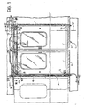
- I a door for an underground railway carriage made according to the invention, mounted facing an opening A, of substantially rectangular shape, provided in one of the sides of the vehicle (not illustrated as a whole).
- Door 1 essentially comprises a pair of panels 2 which are movable between a closed position, which is that shown in Figure 1 and as a continuous line in Figure 3, and an open position, shown by a dashed line only in Figure 3.
- the panels 2 are mounted on a movable frame constituted substantially by a pair of channel-shaped guides 3 which extend through the door opening adjacent the upper ends of the panels 2, and by an assembly of supporting elements of which the essential members of which are two vertical rotary shafts 4 which, together with the horizontal guides 3, give the frame a generally portal-type configuration.
- each panel 2 is provided at its upper end with a suspension member 6 slidable (for example with the interposition of ball bearings) inside the corresponding guide 3.
- the member 6 has a first portion 6a which extends above the respective panel 2, and a further portion 6b which extends towards the other panel 2 and overlies said other panel when the two panels 2 are in the closed position.
- the portion 6b protrudes from the respective panel 2 in a direction opposite that of sliding of the panel itself between the closed position and the open position.
- This particular arrangement of the suspension member 6 is such that, when the respective panel 2 is brought (according to criteria which will be better explained hereinbelow) to the open position, the suspension member 6 itself continues to extend to a substantial degree inside the guide 3.
- the panel 2 is supported by the suspension member 6 under conditions which, from the point of view of the forces acting, are substantially identical in the closed position and in the open position.
- the connection arrangement of each panel 2 to the respective suspension member is chosen so that the panel 2 is held constantly in the substantially barycentric position. This prevents the suspension member 6 having to resist unbalancing moments tending to tilt the panel about the vertical.
- the shafts 4 are each provided with a pair of swing arms 8 which extend in a horizontal direction and support, by means of their facing free ends, a bushing 9 with a horizontal axis.
- the bushing 9 slides on a shaft which is also horizontal and is held at its ends by supports II fixed on the guides 3 on the side of the guides opposite the panels 2.
- the arrangement is such that, as a result of a controlled rotation of the shafts 4, the arms 8 are able to swing in such a manner as to move the guides 3 between a first position - illustrated by a continuous line in Figure 3 - in which the two guides 3 extend in a first plane substantially aligned with the external surface of the body of the vehicle, and a second position - illustrated by a dashed line in Figure 3 - in which the guides 3 extend in a second plane, parallel to the first plane and shifted relative to the latter outwards from the carriage, by a distance of the order of 50 mm.
- the guides 3 may be brought to the above-described first position of operation merely holding the panels 2 in the closed position, or in the position in which each panel is aligned with a respective portion of the door opening, occluding it. As will be seen more easily from Figure 3, under these conditions the panels 2 are in fact locked in a position of alignment with the door opening. The sliding of the actual panels on the guides 3 in the direction corresponding to the moving apart of the panels (opening of the doors) is in fact prevented by the bearing of the outer side of each panel against the vertical side of the opening A which directly faces it. Under such conditions, the door I is thus securely locked in the closed position.
- the panels 2 may be made to slide freely on the guides 3 under the action of respective pneumatic control jacks 12 disposed adjacent the upper ends of the panels 2, near the guides 3.
- each jack 12 is connected at a first end 12a to one of the vertical sides of the opening A and acts at its opposite end 12b on a bracket 13 fixed to the respective panel 2.
- the brackets 13 are mounted on the panels 2 adjacent the facing vertical edges of the panels themselves.
- each jack 12 is mounted adjacent one of the panels but in reality drives the movement of the other panel.
- the jacks 12 With the panels in the closed position, the jacks 12, with the respective rods in their fully-retracted positions, lie in two superposed horizontal planes and are vertically aligned in a direction substantially parallel to the guides 3.
- the free ends 12b of the jacks 12 are also slightly expelled towards the outside of the vehicle. Subsequent operation of the jacks causes the rods to extend from the cylinders and causes each jack 12 to exert a pushing force on the respective panel (which, as has been seen, is the opposite one from that against which the jack 12 is placed) with, as a consequence, the moving apart of the panels 2 and the opening of the door.
- the first movement effected by the rotation of the shafts 4, is that which produces the translation of the guides 3, that is of the doorframe, towards the outside of the vehicle.
- the second movement is the sliding movement in a straight line of the panels 2 on the guides 3 driven by the jacks 12.
- the first of these is the sliding movement in a straight line of the panels 2 on the guides 3 controlled by the jacks 12, while the second is the return movement of the guides 3 into the carriage, effected by the rotation of the shafts 4 in the opposite sense from that used during the opening operation.
- each shaft 4 Adjacent its lower end, each shaft 4 is in addition provided with a further arm 14 which carries at its free end a wheel or roller 15 able to run inside a horizontally-extending channel-shaped guide 16 mounted on the inside face of the respective panel 2.
- the unit formed by the arm 14, the wheel or roller 15, and the channel-shaped guide 16, is intended to hold the respective panel 2, preventing its lower end from rocking relative to the vehicle.
- the panel 2 is in fact, so as to speak, suspended from the member 6 slidably mounted inside the guide 3 situated adjacent the upper end of the panel 2.
- the arm 4 follows the swivelling movements of the arms 8 induced by the rotation of the shaft 4, allowing the panel 2 to be held in a vertical position when the guides 3 project outside the vehicle.
- the presence of the wheel or roller 15 means that, when the guides 3 project outside the vehicle, the panel 2 can slide freely relative to the arm 14, without the latter preventing the movement of panel 2 itself.
- a bracket member 17 may be provided in correspondence with the lower edge of each panel 2, the bracket member being provided with an opening 18 having a vertical axis, able to act as a catch for a bolt 19.
- the bolt 19 is movable in a vertical direction under the action of a pushing member 20, itself moved by an eccentric keyed on the shaft 4 below the floor P of the carriage.
- the first requirement is to ensure that the rotational or swinging movements of the shafts 4 - and, consequently, the sliding movements of the two panels 2 - are synchronised.
- the second requirement is to ensure that the guides 3 are held securely in their positions inside the carriage when the door is in the closed position and are expelled towards the outside of the vehicle only as a result of a positive control action. In other words, it is imperative to prevent the guides 3 from being expelled outside the vehicle, which would allow the eventual sliding and opening of the panels 2, as a consequence of a breakdown leading to a drop in the supply (hydraulic and/or electric) to the actuating members.
- the solution adopted is to combine an actuating device with only one of the shafts 4, utilising a transmission member for the transmission of the movement to the other shaft 4.
- the actuating device represented overall by 22, is associated with the shaft 4 which is on the left-hand side of Figures Ito 3.
- the device 22 acts on the free end of a crank 23 keyed the upper end of said left-hand shaft 4.
- the crank 23 is able to swing between a first operating position X', illustrated by means of a continuous line, and a second operating position X", shown by a dashed line.
- the other end of the transmission rod 25 acts on reversing transmission gearing 26 comprising a first toothed wheel or segment 27 whose rotation is governed by a crank 28 the free end of which is connected to the transmission rod 25, and by a driven toothed wheel or segment 29 keyed on the upper end of the other shaft 4.
- the transmission rod 25 causes a corresponding synchronised rotary movement of the other shaft 4, in the opposite sense, however.
- Figure 4 illustrates on a greater scale the structure of the actuating device 22, the purpose of which, as has been seen, is to drive the rotational movement of the shaft 4 by means of the crank 23 keyed to the upper end of actual shaft 4.
- the device 22 includes a support plate 30 fixed on the structure of the carriage.
- An arm 31 which can swivel about a generally vertical axis, is mounted on the plate 30. More precisely, the arm 31 has a first end 32 hinged in a fixed position relative to the plate 30, a free end 33 and an intermediate region 34 to which there is fixed one of the ends of a drive arm 35 consisting substantially of a pneumatic jack able to contract and expand selectively depending on commands given to it by an electropneumatic control unit (not shown).
- the jack 35 has two ends. The first is denoted by 35a and is joined to the free end of the crank 23 which controls the swinging of arm 4. The second, denoted by 35b, is joined to the swinging arm 31.
- Latch 38 is movable in a substantially radial direction relative to the shaft 4 and to the crank 23 in an arrangement such that:-
- the latch 38 is biassed towards its first operating position, that is to say towards the position which effects the locking of the movement of the crank 23, by a flat spring 39.
- the angular position X' is that which the crank 23 adopts when the shaft 4 controlled by it is situated in the position in which the guides 3 which support the panels 2 are returned inside the carriage.
- the angular position X" is the position to which the crank 23 must be recalled to induce in the shaft 4 the movement which causes the expulsion of the guides 3 towards the outside of the carriage.
- the swinging movement of the crank 23 between the angular positions X' and X" is driven by the jack 35.
- the jack 35 retracts, it pulls the crank 23 back towards the angular position X " .
- the jack 35 expands, on the other hand, it pushes the crank 23 towards the first angular position X'.
- the expansion of the jack 35 has, in addition, the effect of swinging the arm 31 in the direction corresponding to the moving of the arm itself away from crank 23.
- the swinging arm 31 also moves the transmission arm 37 (which is connected at its end 37a to the free end 33 of the swinging arm 31), leaving the latch 38 free to move into a position of engagement with the crank 23 under the action of the return spring 39.
- the jack 35 when the jack 35 is given an expansion command to bring about the return of the guides 3 towards the inside of the carriage, it not only effects the necessary rotation of the shaft 4 controlled by it (and also of the other shaft 4 through the transmission rod 25) but also sets the latch 38 which locks the crank 23 securely in the first angular position X'.
- the intermediate part 34 of the swinging arm 31 is made to come nearer the crank 23.
- the transmission arm 37 is thus pushed from by free end 33 of the actual swinging arm 31 causing the penetration of the end 37b into the seat of the latch 38.
- the latch 38 is thus moved away from the crank 23 and said crank may subsequently be shifted towards the angular position X" as a result of the full retraction of the jack 35.
- an auxiliary arm 40 is mounted on the transmission arm 37 which controls the operation of the latch 38, the arm 40 being connected to two flexible control cables provided with operating levers 41 and 42 disposed respectively inside (lever 41 in Figure 2) and outside (lever 42 in Figure 1) the door I.
- the effect of the operation of one of the controls 41 or 42 is to cause the penetration of the end 37b of the arm 37 to penetrate the housing of the latch 38, according to criteria similar to those governing the release of the engagement device of the crank 23 when the jack 35 is retracted.
Landscapes
- Engineering & Computer Science (AREA)
- Mechanical Engineering (AREA)
- Power-Operated Mechanisms For Wings (AREA)
- Vehicle Interior And Exterior Ornaments, Soundproofing, And Insulation (AREA)
- Support Devices For Sliding Doors (AREA)
- Body Structure For Vehicles (AREA)
- Lock And Its Accessories (AREA)
- Train Traffic Observation, Control, And Security (AREA)
Claims (7)
Priority Applications (1)
| Application Number | Priority Date | Filing Date | Title |
|---|---|---|---|
| AT86830186T ATE56188T1 (de) | 1985-12-11 | 1986-07-02 | Fahrzeugtuer, insbesondere fuer schienen und u-bahn-personenwagen. |
Applications Claiming Priority (2)
| Application Number | Priority Date | Filing Date | Title |
|---|---|---|---|
| IT68040/85A IT1184012B (it) | 1985-12-11 | 1985-12-11 | Porta per veicolo particolarmente veicoli ferroviari e di metropolitane |
| IT6804085 | 1985-12-11 |
Publications (3)
| Publication Number | Publication Date |
|---|---|
| EP0225855A2 EP0225855A2 (fr) | 1987-06-16 |
| EP0225855A3 EP0225855A3 (en) | 1987-12-02 |
| EP0225855B1 true EP0225855B1 (fr) | 1990-09-05 |
Family
ID=11307386
Family Applications (1)
| Application Number | Title | Priority Date | Filing Date |
|---|---|---|---|
| EP86830186A Expired - Lifetime EP0225855B1 (fr) | 1985-12-11 | 1986-07-02 | Porte de véhicule, en particulier pour voitures de chemin de fer ou de métro |
Country Status (4)
| Country | Link |
|---|---|
| EP (1) | EP0225855B1 (fr) |
| AT (1) | ATE56188T1 (fr) |
| DE (1) | DE3673965D1 (fr) |
| IT (1) | IT1184012B (fr) |
Families Citing this family (5)
| Publication number | Priority date | Publication date | Assignee | Title |
|---|---|---|---|---|
| NL9100951A (nl) * | 1991-06-03 | 1993-01-04 | Tbl Beheer Bv | Zwenkschuifdeurstelsel voor een voertuig. |
| ES2058001B1 (es) * | 1991-12-20 | 1996-11-16 | Sab Wabco Dimetal Equipos Ferr | Sistema monoblock de accionamiento de puertas de acceso zig-zag. |
| AT406361B (de) * | 1997-09-10 | 2000-04-25 | Ife Gmbh | Zweiflügelige druckertüchtige türe für ein schienenfahrzeug |
| DE202004002907U1 (de) * | 2004-02-25 | 2004-05-06 | Gebr. Bode Gmbh & Co. Kg | Schiebetür oder Schwenkschiebetür für Fahrzeuge des öffentlichen Personennah- und -fernverkehrs |
| US8701565B2 (en) | 2010-11-17 | 2014-04-22 | Trinity Industries, Inc. | System and method for powered railcar doors |
Family Cites Families (8)
| Publication number | Priority date | Publication date | Assignee | Title |
|---|---|---|---|---|
| DE854664C (de) * | 1941-09-28 | 1952-11-06 | Ver Baubeschlag Gretsch Co | Schwenkschiebetuer, vorzugsweise fuer Schienenfahrzeuge |
| US2552356A (en) * | 1945-04-11 | 1951-05-08 | Nat Pneumatic Co Inc | Vehicle door and operating mechanism |
| FR2031906A5 (fr) * | 1969-02-12 | 1970-11-20 | Venissieux Atel | |
| FR2318299A1 (fr) * | 1975-07-17 | 1977-02-11 | Carel Fouche Et Languepin | Porte louvoyante et coulissante |
| GB2037856B (en) * | 1978-11-28 | 1982-11-17 | Plc Eng Co Ltd | Sliding plug doors |
| DE8322167U1 (de) * | 1983-08-01 | 1983-12-08 | Kiekert GmbH & Co KG, 5628 Heiligenhaus | Schwenkschiebetueraufhaengung fuer fahrzeuge |
| EP0196488B1 (fr) * | 1985-04-01 | 1989-11-15 | Gebrüder Bode & Co. GmbH | Porte pivotante et coulissante, en particulier pour voitures ferroviaires |
| DE8623831U1 (de) * | 1986-09-05 | 1986-10-30 | Kiekert GmbH & Co KG, 5628 Heiligenhaus | Schwenkschiebetür für Fahrzeuge, insbesondere für Personenbeförderungswagen |
-
1985
- 1985-12-11 IT IT68040/85A patent/IT1184012B/it active
-
1986
- 1986-07-02 AT AT86830186T patent/ATE56188T1/de not_active IP Right Cessation
- 1986-07-02 DE DE8686830186T patent/DE3673965D1/de not_active Expired - Fee Related
- 1986-07-02 EP EP86830186A patent/EP0225855B1/fr not_active Expired - Lifetime
Also Published As
| Publication number | Publication date |
|---|---|
| IT1184012B (it) | 1987-10-22 |
| ATE56188T1 (de) | 1990-09-15 |
| IT8568040A0 (it) | 1985-12-11 |
| EP0225855A3 (en) | 1987-12-02 |
| DE3673965D1 (de) | 1990-10-11 |
| EP0225855A2 (fr) | 1987-06-16 |
Similar Documents
| Publication | Publication Date | Title |
|---|---|---|
| US5483769A (en) | Door drive equipment for mass transit vehicle | |
| CA2018076C (fr) | Portiere battante-coulissante pour vehicule | |
| AU2002215295B2 (en) | Vehicle door operating mechanism | |
| US11198498B2 (en) | Opening system and method for an aircraft emergency door | |
| CZ305992A3 (en) | Device for controlling both swinging and sliding movements of a door of motor vehicles for passenger transport, particularly of railway stock | |
| KR20180125146A (ko) | 양문형 슬라이딩 도어 시스템 | |
| CN1068544A (zh) | 一种带锁定机构的电梯门驱动装置 | |
| PT90016B (pt) | Dispositivo de accionamento de portas com mecanismo de bloqueio para elevadores | |
| US20050235564A1 (en) | Swinging sliding door for rail vehicles | |
| AU2002215295A1 (en) | Vehicle door operating mechanism | |
| US4000582A (en) | Oblique-displacement sliding door | |
| EP3792131B1 (fr) | Dispositif d'ouverture et de fermeture de portes de véhicules de transport public | |
| CA2150924C (fr) | Porte coulissante, porte coulissante et louvoyante ou porte escamotable a un ou a deux battants | |
| CN111247303B (zh) | 用于关闭和打开向内转动门的至少一个扇叶的系统 | |
| EP0225855A2 (fr) | Porte de véhicule, en particulier pour voitures de chemin de fer ou de métro | |
| HU191511B (en) | Double-acting door for vehicles | |
| JPS5855313B2 (ja) | 自動車の窓昇降装置 | |
| CN109956385A (zh) | 一种具有防误移的四开门电梯门机系统 | |
| US2861799A (en) | Door operating mechanism | |
| RU165181U1 (ru) | Устройство для открывания и закрывания дверей лифта | |
| RU190231U1 (ru) | Устройство для открывания створок лифта | |
| JPH07172743A (ja) | エレベータの昇降路扉とかご扉の連結装置 | |
| ES2352501T3 (es) | Dispositivo para la regulación de la secuencia de cierre para puertas giratorias de dos hojas. | |
| RU2736663C1 (ru) | Стеклоподъемник с эвакуационным открыванием стекла для бронеавтомобилей | |
| US2022423A (en) | Motor vehicle |
Legal Events
| Date | Code | Title | Description |
|---|---|---|---|
| PUAI | Public reference made under article 153(3) epc to a published international application that has entered the european phase |
Free format text: ORIGINAL CODE: 0009012 |
|
| AK | Designated contracting states |
Kind code of ref document: A2 Designated state(s): AT BE CH DE FR GB IT LI LU NL SE |
|
| PUAL | Search report despatched |
Free format text: ORIGINAL CODE: 0009013 |
|
| AK | Designated contracting states |
Kind code of ref document: A3 Designated state(s): AT BE CH DE FR GB IT LI LU NL SE |
|
| 17P | Request for examination filed |
Effective date: 19880520 |
|
| 17Q | First examination report despatched |
Effective date: 19880922 |
|
| RAP1 | Party data changed (applicant data changed or rights of an application transferred) |
Owner name: WABCO WESTINGHOUSE COMPAGNIA FRENI S.P.A. |
|
| GRAA | (expected) grant |
Free format text: ORIGINAL CODE: 0009210 |
|
| AK | Designated contracting states |
Kind code of ref document: B1 Designated state(s): AT BE CH DE FR GB IT LI LU NL SE |
|
| REF | Corresponds to: |
Ref document number: 56188 Country of ref document: AT Date of ref document: 19900915 Kind code of ref document: T |
|
| ITF | It: translation for a ep patent filed | ||
| REF | Corresponds to: |
Ref document number: 3673965 Country of ref document: DE Date of ref document: 19901011 |
|
| ET | Fr: translation filed | ||
| PGFP | Annual fee paid to national office [announced via postgrant information from national office to epo] |
Ref country code: CH Payment date: 19910619 Year of fee payment: 6 |
|
| PGFP | Annual fee paid to national office [announced via postgrant information from national office to epo] |
Ref country code: BE Payment date: 19910624 Year of fee payment: 6 |
|
| PGFP | Annual fee paid to national office [announced via postgrant information from national office to epo] |
Ref country code: SE Payment date: 19910626 Year of fee payment: 6 |
|
| PGFP | Annual fee paid to national office [announced via postgrant information from national office to epo] |
Ref country code: LU Payment date: 19910628 Year of fee payment: 6 |
|
| PLBE | No opposition filed within time limit |
Free format text: ORIGINAL CODE: 0009261 |
|
| STAA | Information on the status of an ep patent application or granted ep patent |
Free format text: STATUS: NO OPPOSITION FILED WITHIN TIME LIMIT |
|
| 26N | No opposition filed | ||
| EPTA | Lu: last paid annual fee | ||
| PG25 | Lapsed in a contracting state [announced via postgrant information from national office to epo] |
Ref country code: LU Free format text: LAPSE BECAUSE OF NON-PAYMENT OF DUE FEES Effective date: 19920702 |
|
| PG25 | Lapsed in a contracting state [announced via postgrant information from national office to epo] |
Ref country code: SE Effective date: 19920703 |
|
| PGFP | Annual fee paid to national office [announced via postgrant information from national office to epo] |
Ref country code: AT Payment date: 19920714 Year of fee payment: 7 |
|
| PG25 | Lapsed in a contracting state [announced via postgrant information from national office to epo] |
Ref country code: LI Effective date: 19920731 Ref country code: CH Effective date: 19920731 Ref country code: BE Effective date: 19920731 |
|
| PGFP | Annual fee paid to national office [announced via postgrant information from national office to epo] |
Ref country code: NL Payment date: 19920731 Year of fee payment: 7 |
|
| BERE | Be: lapsed |
Owner name: WABCO WESTINGHOUSE COMPAGNIA FRENI S.P.A. Effective date: 19920731 |
|
| REG | Reference to a national code |
Ref country code: CH Ref legal event code: PL |
|
| PGFP | Annual fee paid to national office [announced via postgrant information from national office to epo] |
Ref country code: GB Payment date: 19930615 Year of fee payment: 8 |
|
| PG25 | Lapsed in a contracting state [announced via postgrant information from national office to epo] |
Ref country code: AT Effective date: 19930702 |
|
| PG25 | Lapsed in a contracting state [announced via postgrant information from national office to epo] |
Ref country code: NL Effective date: 19940201 |
|
| NLV4 | Nl: lapsed or anulled due to non-payment of the annual fee | ||
| PGFP | Annual fee paid to national office [announced via postgrant information from national office to epo] |
Ref country code: DE Payment date: 19940627 Year of fee payment: 9 |
|
| PG25 | Lapsed in a contracting state [announced via postgrant information from national office to epo] |
Ref country code: GB Effective date: 19940702 |
|
| PGFP | Annual fee paid to national office [announced via postgrant information from national office to epo] |
Ref country code: FR Payment date: 19940729 Year of fee payment: 9 |
|
| EUG | Se: european patent has lapsed |
Ref document number: 86830186.2 Effective date: 19930204 |
|
| GBPC | Gb: european patent ceased through non-payment of renewal fee |
Effective date: 19940702 |
|
| PG25 | Lapsed in a contracting state [announced via postgrant information from national office to epo] |
Ref country code: DE Effective date: 19960402 |
|
| PG25 | Lapsed in a contracting state [announced via postgrant information from national office to epo] |
Ref country code: FR Effective date: 19960430 |
|
| REG | Reference to a national code |
Ref country code: FR Ref legal event code: ST |
|
| REG | Reference to a national code |
Ref country code: FR Ref legal event code: ST |
|
| REG | Reference to a national code |
Ref country code: FR Ref legal event code: ST |
|
| PG25 | Lapsed in a contracting state [announced via postgrant information from national office to epo] |
Ref country code: IT Free format text: LAPSE BECAUSE OF NON-PAYMENT OF DUE FEES;WARNING: LAPSES OF ITALIAN PATENTS WITH EFFECTIVE DATE BEFORE 2007 MAY HAVE OCCURRED AT ANY TIME BEFORE 2007. THE CORRECT EFFECTIVE DATE MAY BE DIFFERENT FROM THE ONE RECORDED. Effective date: 20050702 |