EP0225862A1 - Corps creux comportant une fermeture étanche à l'eau à ses extrémités - Google Patents
Corps creux comportant une fermeture étanche à l'eau à ses extrémités Download PDFInfo
- Publication number
- EP0225862A1 EP0225862A1 EP86870163A EP86870163A EP0225862A1 EP 0225862 A1 EP0225862 A1 EP 0225862A1 EP 86870163 A EP86870163 A EP 86870163A EP 86870163 A EP86870163 A EP 86870163A EP 0225862 A1 EP0225862 A1 EP 0225862A1
- Authority
- EP
- European Patent Office
- Prior art keywords
- hollow body
- plug
- piston plate
- orifice
- chamber
- Prior art date
- Legal status (The legal status is an assumption and is not a legal conclusion. Google has not performed a legal analysis and makes no representation as to the accuracy of the status listed.)
- Granted
Links
- 229920002994 synthetic fiber Polymers 0.000 claims abstract description 9
- 239000002184 metal Substances 0.000 claims abstract description 5
- 239000000126 substance Substances 0.000 claims abstract description 3
- 230000008030 elimination Effects 0.000 claims description 4
- 238000003379 elimination reaction Methods 0.000 claims description 4
- 239000000853 adhesive Substances 0.000 claims description 3
- 230000001070 adhesive effect Effects 0.000 claims description 3
- 239000003292 glue Substances 0.000 abstract description 2
- 238000004519 manufacturing process Methods 0.000 description 4
- 230000009182 swimming Effects 0.000 description 2
- 238000009825 accumulation Methods 0.000 description 1
- 239000000463 material Substances 0.000 description 1
- 238000000034 method Methods 0.000 description 1
- 230000001681 protective effect Effects 0.000 description 1
- 230000005855 radiation Effects 0.000 description 1
- 239000003566 sealing material Substances 0.000 description 1
- XLYOFNOQVPJJNP-UHFFFAOYSA-N water Substances O XLYOFNOQVPJJNP-UHFFFAOYSA-N 0.000 description 1
Images
Classifications
-
- B—PERFORMING OPERATIONS; TRANSPORTING
- B29—WORKING OF PLASTICS; WORKING OF SUBSTANCES IN A PLASTIC STATE IN GENERAL
- B29C—SHAPING OR JOINING OF PLASTICS; SHAPING OF MATERIAL IN A PLASTIC STATE, NOT OTHERWISE PROVIDED FOR; AFTER-TREATMENT OF THE SHAPED PRODUCTS, e.g. REPAIRING
- B29C65/00—Joining or sealing of preformed parts, e.g. welding of plastics materials; Apparatus therefor
- B29C65/48—Joining or sealing of preformed parts, e.g. welding of plastics materials; Apparatus therefor using adhesives, i.e. using supplementary joining material; solvent bonding
- B29C65/52—Joining or sealing of preformed parts, e.g. welding of plastics materials; Apparatus therefor using adhesives, i.e. using supplementary joining material; solvent bonding characterised by the way of applying the adhesive
- B29C65/54—Joining or sealing of preformed parts, e.g. welding of plastics materials; Apparatus therefor using adhesives, i.e. using supplementary joining material; solvent bonding characterised by the way of applying the adhesive between pre-assembled parts
-
- B—PERFORMING OPERATIONS; TRANSPORTING
- B29—WORKING OF PLASTICS; WORKING OF SUBSTANCES IN A PLASTIC STATE IN GENERAL
- B29C—SHAPING OR JOINING OF PLASTICS; SHAPING OF MATERIAL IN A PLASTIC STATE, NOT OTHERWISE PROVIDED FOR; AFTER-TREATMENT OF THE SHAPED PRODUCTS, e.g. REPAIRING
- B29C66/00—General aspects of processes or apparatus for joining preformed parts
- B29C66/50—General aspects of joining tubular articles; General aspects of joining long products, i.e. bars or profiled elements; General aspects of joining single elements to tubular articles, hollow articles or bars; General aspects of joining several hollow-preforms to form hollow or tubular articles
- B29C66/51—Joining tubular articles, profiled elements or bars; Joining single elements to tubular articles, hollow articles or bars; Joining several hollow-preforms to form hollow or tubular articles
- B29C66/53—Joining single elements to tubular articles, hollow articles or bars
- B29C66/534—Joining single elements to open ends of tubular or hollow articles or to the ends of bars
-
- E—FIXED CONSTRUCTIONS
- E04—BUILDING
- E04H—BUILDINGS OR LIKE STRUCTURES FOR PARTICULAR PURPOSES; SWIMMING OR SPLASH BATHS OR POOLS; MASTS; FENCING; TENTS OR CANOPIES, IN GENERAL
- E04H4/00—Swimming or splash baths or pools
- E04H4/06—Safety devices; Coverings for baths
- E04H4/08—Coverings consisting of rigid elements, e.g. coverings composed of separate or connected elements
- E04H4/082—Coverings consisting of rigid elements, e.g. coverings composed of separate or connected elements composed of flexibly or hingedly-connected slat-like elements, which may or may not be wound-up on a fixed axis
-
- B—PERFORMING OPERATIONS; TRANSPORTING
- B29—WORKING OF PLASTICS; WORKING OF SUBSTANCES IN A PLASTIC STATE IN GENERAL
- B29C—SHAPING OR JOINING OF PLASTICS; SHAPING OF MATERIAL IN A PLASTIC STATE, NOT OTHERWISE PROVIDED FOR; AFTER-TREATMENT OF THE SHAPED PRODUCTS, e.g. REPAIRING
- B29C65/00—Joining or sealing of preformed parts, e.g. welding of plastics materials; Apparatus therefor
- B29C65/48—Joining or sealing of preformed parts, e.g. welding of plastics materials; Apparatus therefor using adhesives, i.e. using supplementary joining material; solvent bonding
- B29C65/52—Joining or sealing of preformed parts, e.g. welding of plastics materials; Apparatus therefor using adhesives, i.e. using supplementary joining material; solvent bonding characterised by the way of applying the adhesive
- B29C65/54—Joining or sealing of preformed parts, e.g. welding of plastics materials; Apparatus therefor using adhesives, i.e. using supplementary joining material; solvent bonding characterised by the way of applying the adhesive between pre-assembled parts
- B29C65/542—Joining or sealing of preformed parts, e.g. welding of plastics materials; Apparatus therefor using adhesives, i.e. using supplementary joining material; solvent bonding characterised by the way of applying the adhesive between pre-assembled parts by injection
-
- B—PERFORMING OPERATIONS; TRANSPORTING
- B29—WORKING OF PLASTICS; WORKING OF SUBSTANCES IN A PLASTIC STATE IN GENERAL
- B29C—SHAPING OR JOINING OF PLASTICS; SHAPING OF MATERIAL IN A PLASTIC STATE, NOT OTHERWISE PROVIDED FOR; AFTER-TREATMENT OF THE SHAPED PRODUCTS, e.g. REPAIRING
- B29C66/00—General aspects of processes or apparatus for joining preformed parts
- B29C66/01—General aspects dealing with the joint area or with the area to be joined
- B29C66/05—Particular design of joint configurations
- B29C66/10—Particular design of joint configurations particular design of the joint cross-sections
- B29C66/12—Joint cross-sections combining only two joint-segments; Tongue and groove joints; Tenon and mortise joints; Stepped joint cross-sections
- B29C66/122—Joint cross-sections combining only two joint-segments, i.e. one of the parts to be joined comprising only two joint-segments in the joint cross-section
- B29C66/1222—Joint cross-sections combining only two joint-segments, i.e. one of the parts to be joined comprising only two joint-segments in the joint cross-section comprising at least a lapped joint-segment
-
- B—PERFORMING OPERATIONS; TRANSPORTING
- B29—WORKING OF PLASTICS; WORKING OF SUBSTANCES IN A PLASTIC STATE IN GENERAL
- B29C—SHAPING OR JOINING OF PLASTICS; SHAPING OF MATERIAL IN A PLASTIC STATE, NOT OTHERWISE PROVIDED FOR; AFTER-TREATMENT OF THE SHAPED PRODUCTS, e.g. REPAIRING
- B29C66/00—General aspects of processes or apparatus for joining preformed parts
- B29C66/01—General aspects dealing with the joint area or with the area to be joined
- B29C66/05—Particular design of joint configurations
- B29C66/10—Particular design of joint configurations particular design of the joint cross-sections
- B29C66/12—Joint cross-sections combining only two joint-segments; Tongue and groove joints; Tenon and mortise joints; Stepped joint cross-sections
- B29C66/122—Joint cross-sections combining only two joint-segments, i.e. one of the parts to be joined comprising only two joint-segments in the joint cross-section
- B29C66/1224—Joint cross-sections combining only two joint-segments, i.e. one of the parts to be joined comprising only two joint-segments in the joint cross-section comprising at least a butt joint-segment
-
- B—PERFORMING OPERATIONS; TRANSPORTING
- B29—WORKING OF PLASTICS; WORKING OF SUBSTANCES IN A PLASTIC STATE IN GENERAL
- B29C—SHAPING OR JOINING OF PLASTICS; SHAPING OF MATERIAL IN A PLASTIC STATE, NOT OTHERWISE PROVIDED FOR; AFTER-TREATMENT OF THE SHAPED PRODUCTS, e.g. REPAIRING
- B29C66/00—General aspects of processes or apparatus for joining preformed parts
- B29C66/50—General aspects of joining tubular articles; General aspects of joining long products, i.e. bars or profiled elements; General aspects of joining single elements to tubular articles, hollow articles or bars; General aspects of joining several hollow-preforms to form hollow or tubular articles
- B29C66/51—Joining tubular articles, profiled elements or bars; Joining single elements to tubular articles, hollow articles or bars; Joining several hollow-preforms to form hollow or tubular articles
- B29C66/54—Joining several hollow-preforms, e.g. half-shells, to form hollow articles, e.g. for making balls, containers; Joining several hollow-preforms, e.g. half-cylinders, to form tubular articles
- B29C66/543—Joining several hollow-preforms, e.g. half-shells, to form hollow articles, e.g. for making balls, containers; Joining several hollow-preforms, e.g. half-cylinders, to form tubular articles joining more than two hollow-preforms to form said hollow articles
- B29C66/5432—Joining several hollow-preforms, e.g. half-shells, to form hollow articles, e.g. for making balls, containers; Joining several hollow-preforms, e.g. half-cylinders, to form tubular articles joining more than two hollow-preforms to form said hollow articles joining hollow covers and hollow bottoms to open ends of container bodies
-
- B—PERFORMING OPERATIONS; TRANSPORTING
- B29—WORKING OF PLASTICS; WORKING OF SUBSTANCES IN A PLASTIC STATE IN GENERAL
- B29C—SHAPING OR JOINING OF PLASTICS; SHAPING OF MATERIAL IN A PLASTIC STATE, NOT OTHERWISE PROVIDED FOR; AFTER-TREATMENT OF THE SHAPED PRODUCTS, e.g. REPAIRING
- B29C66/00—General aspects of processes or apparatus for joining preformed parts
- B29C66/50—General aspects of joining tubular articles; General aspects of joining long products, i.e. bars or profiled elements; General aspects of joining single elements to tubular articles, hollow articles or bars; General aspects of joining several hollow-preforms to form hollow or tubular articles
- B29C66/51—Joining tubular articles, profiled elements or bars; Joining single elements to tubular articles, hollow articles or bars; Joining several hollow-preforms to form hollow or tubular articles
- B29C66/54—Joining several hollow-preforms, e.g. half-shells, to form hollow articles, e.g. for making balls, containers; Joining several hollow-preforms, e.g. half-cylinders, to form tubular articles
- B29C66/545—Joining several hollow-preforms, e.g. half-shells, to form hollow articles, e.g. for making balls, containers; Joining several hollow-preforms, e.g. half-cylinders, to form tubular articles one hollow-preform being placed inside the other
Definitions
- the present invention relates to a hollow body made of synthetic material or metal comprising a watertight closure at each of its ends, said closure consisting of a plug which can be fitted at the open end of the hollow body and comprising an extension s inserting into the hollow body, as well as an orifice intended for the introduction of an adhesive or other similar substance.
- the problem is particularly important for swimming pool covers in transparent and colored extruded synthetic material, where the lower side is black and the upper side is transparent. It is also important that the top surface of such blankets is not a dark shade at the ends of the blades, since a possible accumulation of heat produced by solar radiation can easily cause expansion of the material and a leak.
- patent DE-GM 85 18 954.5 the applicant proposed an embodiment where a rod substantially closed the cross section of the hollow body and had peripherally a groove or groove which can be filled with glue. This embodiment requires an excessively precise application of the adhesive and nevertheless does not offer sufficient security.
- the object of the present invention is therefore to provide a more economical and technically safer possibility of producing a watertight closure of a hollow body.
- the piston plates simply form an internal delimitation of the chambers into which the filling mass is introduced and at the same time represent a plane against which the filling mass comes to bear.
- This filling mass can completely fill the chamber formed between the plate- piston and plug, so that better water-tightness security is obtained even during imprecise manufacture of the profile or during large tolerances between the plug and the hollow body, as well as during expansion thermal.
- Filling can take place by the plug or by one of the side walls of the hollow body.
- a second port makes it possible to check whether the filling chamber is completely filled. At the same time, such an additional orifice makes it possible to evacuate the air contained within the chamber.
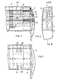
- Figure 1 shows a hollow body 1 having the shape of a part of a rotating shutter blade, comprising a plug 2, which is shown in Figure 2 in a view from above.
- the rotating shutter blade has two parallel axial chambers 3, 4, separated from each other by a wall 5.
- the hollow body 1 is extruded and is made of synthetic material or of light metal.
- the plug 2 has a bottom 6 and an extension 7 formed in one piece with the bottom 6 and having two rods corresponding to the chambers 3, 4.
- the extension 7 comprises in particular, for each of the chambers 3, 4, a rod 8 relatively thin provided, at its free end, with a piston plate 9 closing the cross section of the corresponding chamber 3 or 4.
- filling orifices 10 are provided as well as air discharge orifices 11 in the bottom 6 of the plug 2.
- the orifices 10 are provided for the introduction of a filling mass 13 retaining a permanent elasticity, preferably a synthetic material of the type generally known among sealing materials.
- a filling mass 13 retaining a permanent elasticity, preferably a synthetic material of the type generally known among sealing materials.
- Air filling and elimination orifices 10 ′ and 11 ′ may also, as shown in FIG. 3, be provided direc ment in one of the side walls of the hollow body 1 and in reality in the region of the chamber 12 formed between the piston plate 9 and the bottom 6 of the plug 2. In this case also, a single orifice can be envisaged each time.
Landscapes
- Engineering & Computer Science (AREA)
- Mechanical Engineering (AREA)
- Architecture (AREA)
- Civil Engineering (AREA)
- Structural Engineering (AREA)
- Building Environments (AREA)
- Coating Apparatus (AREA)
- Pressure Vessels And Lids Thereof (AREA)
- Extrusion Moulding Of Plastics Or The Like (AREA)
- Examining Or Testing Airtightness (AREA)
- Toys (AREA)
Abstract
Description
- La présente invention concerne un corps creux en matière synthétique ou en métal comportant une fermeture étanche à l'eau à chacune de ses extrémités, ladite fermeture étant constituée par un bouchon pouvant être emboîté à l'extrémité ouverte du corps creux et comportant un prolongement s'insérant dans le corps creux, ainsi qu'un orifice destiné à l'introduction d'une colle ou autre substance similaire.
- Dans la pratique, il est souvent problématique de rendre étanche à l'eau les extrémités des profilés creux en matière synthétique ou en métal léger, afin de permettre à ces corps creux de flotter. Cette étanchéité est importante lors de la fabrication d'engins nautiques, mais également en particulier lors de la réalisation de couvertures de piscines au moyen de volets roulants de protection, lesquels sont déroulés à la surface de l'eau.
- Le problème est particulièrement important pour les couvertures de piscines en matière synthétique extrudée transparente et colorée, où le côté inférieur est de teinte noire et le côté supérieur est transparent. Il est également important que la surface supérieure de telles couvertures ne soit pas de teinte sombre aux extrémités des lames, étant donné qu'une éventuelle accumulation de chaleur produite par la radiation solaire peut aisément provoquer une dilatation de la matière et un défaut d'étanchéité.
- Différentes tentatives d'installation de bouchons d'étanchéité à l'eau sur de tels profilés creux ont déjà été faites, mais ne donnèrent pas de résultats satisfaisants sur le plan des techniques de fabrication et en particulier pour des raisons thermiques.
- Dans le brevet DE-GM 85 18 954.5, le demandeur proposait une forme de réalisation où une tige venait substantiellement obturer la section transversale du corps creux et présentait périphériquement une gorge ou rainure pouvant être remplie de colle. Cette forme de réalisation requiert une application excessivement précise de la colle et n'offre malgré tout pas une sécurité suffisante.
- L'objet de la présente invention, en se basant sur cet état de la technique, est dés lors de fournir une possibilité plus économique et techniquement plus sûre de réaliser une fermeture étanche à l'eau d'un corps creux.
- A cet effet, il est prévu les caractéristiques énoncées à la revendication 1.
- Les plaques-pistons forment simplement une délimitation interne des chambres au sein desquelles la masse de remplissage est introduite et représentent en même temps un plan contre lequel la masse de remplissage vient appuyer. Cette masse de remplissage peut combler entièrement la chambre formée entre la plaque- piston et le bouchon, de sorte qu'une meilleure sécurité d'étanchéité à l'eau est obtenue même lors d'une fabrication imprécise du profilé ou lors de tolérances importantes entre le bouchon et le corps creux, ainsi que lors d'une dilatation thermique.
- Le remplissage peut avoir lieu par le bouchon ou par une des parois latérales du corps creux. Un deuxième orifice permet de vérifier si la chambre de remplissage est entièrement remplie. En même temps, un tel orifice supplémentaire permet d'évacuer l'air contenu au sein de la chambre.
- La présente invention est exposée par la suite de manière plus détaillée, par référence au dessin. Il y est représenté :
- Figure 1 une coupe longitudinale d'une partie d'une lame de volet roulant, suivant la ligne I-I à la figure 2,
- Figure 2 une vue d'en haut d'un bouchon et
- Figure 3 une vue de côté d'une partie d'une autre lame de volet roulant.
- La figure 1 montre un corps creux 1 possédant la forme d'une partie d'une lame de volet tournant, comportant un bouchon 2, lequel est représenté à la figure 2 suivant une vue d'en haut. La lame de volet tournant présente deux chambres 3, 4 axiales parallèles, séparées l'une de l'autre par une paroi 5. Le corps creux 1 est extrudé et est en matière synthétique ou en métal léger.
- Le bouchon 2 présente un fond 6 et un prolongement 7 formé d'une seule pièce avec le fond 6 et présentant deux tiges correspondant aux chambres 3, 4. Le prolongement 7 comporte en particulier, pour chacune des chambres 3, 4, une tige 8 relativement mince pourvue, à son extrémité libre, d'une plaque-piston 9 obturant la section transversale de la chambre 3 ou 4 correspondante.
- Dans l'exemple de réalisation suivant les figures 1 et 2, il est prévu des orifices de remplissage 10 ainsi que des orifices d'évacuation d'air 11 dans le fond 6 du bouchon 2.
- Les orifices 10 sont prévus pour l'introduction d'une masse de remplissage 13 conservant une élasticité permanente, de préférence une matière synthétique du type généralement connu parmi les matériaux d'étanchéité. Lorsque la chambre 12 formée entre le bouchon 2 et la plaque-piston 9 est remplie de cette masse de remplissage 13, il est obtenu une fermeture étanche à l'eau. La masse de remplissage vient appuyer contre la plaque-piston 9 et n'aboutit pas dans l'autre partie du corps creux 1. Le remplissage complet de la chambre 3, 4 est obtenu avec certitude dès qu'un excès de masse de remplissage 13 sort hors de l'orifice d'élimination d'air 11.
- Au lieu de prévoir chaque fois un orifice de remplissage 10 et un orifice d'élimination d'air 11, il peut également être envisagé un seul orifice. De même, il n'est pas indispensable que les orifices se situent dans le fond 6 du bouchon 2. Des orifices de remplissage et d'élimination d'air 10′ et 11′ peuvent également, comme le montre la figure 3, être prévus direc tement dans une des parois latérales du corps creux 1 et en réalité dans la région de la chambre 12 formée entre la plaque-piston 9 et le fond 6 du bouchon 2. Dans ce cas également, il peut être envisagé chaque fois un seul orifice.
Claims (3)
Priority Applications (1)
| Application Number | Priority Date | Filing Date | Title |
|---|---|---|---|
| AT86870163T ATE50817T1 (de) | 1985-11-06 | 1986-11-05 | Hohlkoerper mit einem wasserdichten verschluss an seinen aeusseren enden. |
Applications Claiming Priority (2)
| Application Number | Priority Date | Filing Date | Title |
|---|---|---|---|
| DE8531338U DE8531338U1 (de) | 1985-11-06 | 1985-11-06 | Hohlkörper mit wasserdichtem Bodenverschluss |
| DE8531338U | 1985-11-06 |
Publications (2)
| Publication Number | Publication Date |
|---|---|
| EP0225862A1 true EP0225862A1 (fr) | 1987-06-16 |
| EP0225862B1 EP0225862B1 (fr) | 1990-03-07 |
Family
ID=6786980
Family Applications (1)
| Application Number | Title | Priority Date | Filing Date |
|---|---|---|---|
| EP86870163A Expired - Lifetime EP0225862B1 (fr) | 1985-11-06 | 1986-11-05 | Corps creux comportant une fermeture étanche à l'eau à ses extrémités |
Country Status (4)
| Country | Link |
|---|---|
| EP (1) | EP0225862B1 (fr) |
| AT (1) | ATE50817T1 (fr) |
| DE (2) | DE8531338U1 (fr) |
| ES (1) | ES2014253B3 (fr) |
Cited By (6)
| Publication number | Priority date | Publication date | Assignee | Title |
|---|---|---|---|---|
| FR2697271A1 (fr) * | 1992-10-28 | 1994-04-29 | Belpaume Charles | Panneau souple enroulable de fermeture, notamment pour recouvrir une piscine extérieure. |
| DE19508953C1 (de) * | 1995-03-13 | 1996-06-20 | Helge Hans Heinz | Hohlkörper mit wasserdichtem Verschluß |
| FR2820771A1 (fr) | 2001-02-14 | 2002-08-16 | Distrib Et D Equipement Soc De | Couverture flottante de piscine |
| NL1021102C2 (nl) | 2002-07-18 | 2004-01-20 | Pooltechnics B V | Afdichtorgaan voor een hol profiel. |
| US6910233B2 (en) | 2002-08-15 | 2005-06-28 | Hans Heinz Helge | Elongated roller shutter profile made of plastic or metal for swimming pool covers |
| BE1015882A3 (nl) | 2004-02-04 | 2005-10-04 | Zwembadafdekking. |
Families Citing this family (1)
| Publication number | Priority date | Publication date | Assignee | Title |
|---|---|---|---|---|
| DE102018003137A1 (de) * | 2018-04-06 | 2019-10-10 | Siegfried Binder | Aufrollbare schwimmbeckenabdeckung mit einer vielzahl von paralell zueinander angeordneten lamellenblätter |
Citations (4)
| Publication number | Priority date | Publication date | Assignee | Title |
|---|---|---|---|---|
| FR2223587A1 (fr) * | 1973-03-30 | 1974-10-25 | Harke Alfons | |
| GB2012649A (en) * | 1977-12-22 | 1979-08-01 | Gkn Transmissions Ltd | Tubular shaft and universal joint assembly |
| FR2551792A1 (fr) * | 1983-09-14 | 1985-03-15 | Gautheron Lucien | Procede d'etanchement des profiles en caisson pour couvertures de piscine, et profile ainsi rendu etanche |
| DE8518954U1 (de) * | 1985-06-29 | 1985-10-10 | Helge, Hans Heinz, Dison | Vorrichtung zur Herstellung eines wasserdichten Verschlußes bei einem Hohlkörper |
-
1985
- 1985-11-06 DE DE8531338U patent/DE8531338U1/de not_active Expired
-
1986
- 1986-11-05 ES ES86870163T patent/ES2014253B3/es not_active Expired - Lifetime
- 1986-11-05 DE DE8686870163T patent/DE3669337D1/de not_active Expired - Lifetime
- 1986-11-05 AT AT86870163T patent/ATE50817T1/de not_active IP Right Cessation
- 1986-11-05 EP EP86870163A patent/EP0225862B1/fr not_active Expired - Lifetime
Patent Citations (4)
| Publication number | Priority date | Publication date | Assignee | Title |
|---|---|---|---|---|
| FR2223587A1 (fr) * | 1973-03-30 | 1974-10-25 | Harke Alfons | |
| GB2012649A (en) * | 1977-12-22 | 1979-08-01 | Gkn Transmissions Ltd | Tubular shaft and universal joint assembly |
| FR2551792A1 (fr) * | 1983-09-14 | 1985-03-15 | Gautheron Lucien | Procede d'etanchement des profiles en caisson pour couvertures de piscine, et profile ainsi rendu etanche |
| DE8518954U1 (de) * | 1985-06-29 | 1985-10-10 | Helge, Hans Heinz, Dison | Vorrichtung zur Herstellung eines wasserdichten Verschlußes bei einem Hohlkörper |
Cited By (10)
| Publication number | Priority date | Publication date | Assignee | Title |
|---|---|---|---|---|
| FR2697271A1 (fr) * | 1992-10-28 | 1994-04-29 | Belpaume Charles | Panneau souple enroulable de fermeture, notamment pour recouvrir une piscine extérieure. |
| EP0595725A1 (fr) * | 1992-10-28 | 1994-05-04 | Belpaume, Charles | Panneau souple enroulable de fermeture, notamment pour recouvrir une piscine extérieure |
| US5901770A (en) * | 1992-10-28 | 1999-05-11 | Charles Belpaume | Flexible closure cover which can be rolled onto and unrolled from a rotatable support, particularly for covering an outside swimming pool |
| DE19508953C1 (de) * | 1995-03-13 | 1996-06-20 | Helge Hans Heinz | Hohlkörper mit wasserdichtem Verschluß |
| EP0732469A1 (fr) * | 1995-03-13 | 1996-09-18 | Hans Heinz Helge | Corps creux avec une fermeture étanche |
| US5732846A (en) * | 1995-03-13 | 1998-03-31 | Helge; Hans-Heinz | Hollow body with watertight closure |
| FR2820771A1 (fr) | 2001-02-14 | 2002-08-16 | Distrib Et D Equipement Soc De | Couverture flottante de piscine |
| NL1021102C2 (nl) | 2002-07-18 | 2004-01-20 | Pooltechnics B V | Afdichtorgaan voor een hol profiel. |
| US6910233B2 (en) | 2002-08-15 | 2005-06-28 | Hans Heinz Helge | Elongated roller shutter profile made of plastic or metal for swimming pool covers |
| BE1015882A3 (nl) | 2004-02-04 | 2005-10-04 | Zwembadafdekking. |
Also Published As
| Publication number | Publication date |
|---|---|
| ATE50817T1 (de) | 1990-03-15 |
| DE3669337D1 (de) | 1990-04-12 |
| EP0225862B1 (fr) | 1990-03-07 |
| DE8531338U1 (de) | 1985-12-19 |
| ES2014253B3 (es) | 1990-07-01 |
Similar Documents
| Publication | Publication Date | Title |
|---|---|---|
| CH631010A5 (fr) | Douille de cartouches. | |
| FR2512921A1 (fr) | Systeme pour l'assemblage de plaques a double paroi transparentes | |
| CA1239354A (fr) | Dispositif d'equilibrage de pression etanche aux eaux de pluie ou de ruissellement, notamment pour conteneur de transport | |
| EP0225862B1 (fr) | Corps creux comportant une fermeture étanche à l'eau à ses extrémités | |
| CA2389350C (fr) | Verseur ameliore et capsule a verseur incorpore | |
| FR2961659A1 (fr) | Pot creux comportant une reserve d'eau | |
| EP0961861A1 (fr) | Dispositif de refroidissement pour ensemble compact de pompage et de filtration pour bassin de piscine | |
| EP1028217A1 (fr) | Cadre de fenêtre et son procédé de réalisation | |
| EP2406093B1 (fr) | Profile pour element de fermeture de benne de vehicule et element de fermeture correspondant | |
| WO2005035336A1 (fr) | Obturateur pour partie creuse de vehicule automobile | |
| EP1233125B1 (fr) | Couverture flottante de piscine | |
| FR2813624A1 (fr) | Profile de raccord et d'etancheite, dispositif de raccord, panneau a structure sandwich, et ensemble de facade, de cloison ou de couverture | |
| BE1023830B1 (fr) | Volet de piscine solaire | |
| WO1980002273A1 (fr) | Coiffe en matiere plastique pour fut | |
| FR2480074A1 (fr) | Pot en matiere synthetique thermoplastique, pour plantes | |
| FR2666636A1 (fr) | Dispositif pour isoler, eclairer et reflechir les infra-rouges, des toitures. | |
| EP0695625A1 (fr) | Pièce en résine synthétique en deux parties et son procédé de fabrication | |
| FR2678806A1 (fr) | Aquarium de structure partiellement souple, apte a le rendre pliable sur lui-meme dans une position de stockage ou de transport. | |
| EP0034551B1 (fr) | Procédé de fermeture étanche de récipients par opercules minces | |
| FR2632348A1 (fr) | Profile d'encadrement de vitrage | |
| FR2551481A1 (fr) | Dispositif de maintien et de blocage des elements constituant la structure d'une couverture realisee notamment au moyen d'une bache | |
| FR2695589A1 (fr) | Procédé de fabrication par moulage d'éléments creux tels que des éléments de canalisation en béton à joint d'étanchéité intégré, et dispositif pour la mise en Óoeuvre de ce procédé. | |
| FR2737242A1 (fr) | Embout pour lames tubulaires destinees a etre juxtaposees les unes aux autres et reliees par un systeme de charniere de facon a former un panneau developpable de fermeture ou couverture | |
| FR2614262A1 (fr) | Dispositif de pinoche fonctionnelle auto-etancheiseuse. | |
| BE1000728A7 (fr) | Garniture associee a la base d'un poteau pour couvrir une zone de sol entourant cette derniere. |
Legal Events
| Date | Code | Title | Description |
|---|---|---|---|
| PUAI | Public reference made under article 153(3) epc to a published international application that has entered the european phase |
Free format text: ORIGINAL CODE: 0009012 |
|
| AK | Designated contracting states |
Kind code of ref document: A1 Designated state(s): AT BE CH DE ES FR GB LI NL |
|
| 17P | Request for examination filed |
Effective date: 19871125 |
|
| 17Q | First examination report despatched |
Effective date: 19881118 |
|
| GRAA | (expected) grant |
Free format text: ORIGINAL CODE: 0009210 |
|
| AK | Designated contracting states |
Kind code of ref document: B1 Designated state(s): AT BE CH DE ES FR GB LI NL |
|
| REF | Corresponds to: |
Ref document number: 50817 Country of ref document: AT Date of ref document: 19900315 Kind code of ref document: T |
|
| GBT | Gb: translation of ep patent filed (gb section 77(6)(a)/1977) | ||
| REF | Corresponds to: |
Ref document number: 3669337 Country of ref document: DE Date of ref document: 19900412 |
|
| RAP4 | Party data changed (patent owner data changed or rights of a patent transferred) |
Owner name: HELGE, HANS HEINZ |
|
| PLBE | No opposition filed within time limit |
Free format text: ORIGINAL CODE: 0009261 |
|
| STAA | Information on the status of an ep patent application or granted ep patent |
Free format text: STATUS: NO OPPOSITION FILED WITHIN TIME LIMIT |
|
| BECA | Be: change of holder's address |
Free format text: 900307 *HELGE HANS HEINZ:MANAIHANT 32, B-4822 PETIT-RECHAIN |
|
| 26N | No opposition filed | ||
| REG | Reference to a national code |
Ref country code: GB Ref legal event code: IF02 |
|
| REG | Reference to a national code |
Ref country code: FR Ref legal event code: CL |
|
| PGFP | Annual fee paid to national office [announced via postgrant information from national office to epo] |
Ref country code: BE Payment date: 20051031 Year of fee payment: 20 |
|
| PGFP | Annual fee paid to national office [announced via postgrant information from national office to epo] |
Ref country code: FR Payment date: 20051107 Year of fee payment: 20 |
|
| PGFP | Annual fee paid to national office [announced via postgrant information from national office to epo] |
Ref country code: GB Payment date: 20051108 Year of fee payment: 20 |
|
| PGFP | Annual fee paid to national office [announced via postgrant information from national office to epo] |
Ref country code: DE Payment date: 20051110 Year of fee payment: 20 |
|
| PGFP | Annual fee paid to national office [announced via postgrant information from national office to epo] |
Ref country code: CH Payment date: 20051114 Year of fee payment: 20 |
|
| PGFP | Annual fee paid to national office [announced via postgrant information from national office to epo] |
Ref country code: AT Payment date: 20051115 Year of fee payment: 20 |
|
| PGFP | Annual fee paid to national office [announced via postgrant information from national office to epo] |
Ref country code: NL Payment date: 20051129 Year of fee payment: 20 |
|
| PGFP | Annual fee paid to national office [announced via postgrant information from national office to epo] |
Ref country code: ES Payment date: 20051216 Year of fee payment: 20 |
|
| PG25 | Lapsed in a contracting state [announced via postgrant information from national office to epo] |
Ref country code: GB Free format text: LAPSE BECAUSE OF EXPIRATION OF PROTECTION Effective date: 20061104 |
|
| PG25 | Lapsed in a contracting state [announced via postgrant information from national office to epo] |
Ref country code: NL Free format text: LAPSE BECAUSE OF EXPIRATION OF PROTECTION Effective date: 20061105 |
|
| PG25 | Lapsed in a contracting state [announced via postgrant information from national office to epo] |
Ref country code: ES Free format text: LAPSE BECAUSE OF EXPIRATION OF PROTECTION Effective date: 20061106 |
|
| REG | Reference to a national code |
Ref country code: GB Ref legal event code: PE20 |
|
| REG | Reference to a national code |
Ref country code: CH Ref legal event code: PL |
|
| NLV7 | Nl: ceased due to reaching the maximum lifetime of a patent |
Effective date: 20061105 |
|
| REG | Reference to a national code |
Ref country code: ES Ref legal event code: FD2A Effective date: 20061106 |
|
| BE20 | Be: patent expired |
Owner name: *HELGE HANS HEINZ Effective date: 20061105 |