EP0226076A1 - Automatischer Greifer zum Handhaben von Gegenständen und ein mit diesem Greifer versehener Roboter - Google Patents
Automatischer Greifer zum Handhaben von Gegenständen und ein mit diesem Greifer versehener Roboter Download PDFInfo
- Publication number
- EP0226076A1 EP0226076A1 EP86116249A EP86116249A EP0226076A1 EP 0226076 A1 EP0226076 A1 EP 0226076A1 EP 86116249 A EP86116249 A EP 86116249A EP 86116249 A EP86116249 A EP 86116249A EP 0226076 A1 EP0226076 A1 EP 0226076A1
- Authority
- EP
- European Patent Office
- Prior art keywords
- plate
- grapple
- bricks
- axes
- claw
- Prior art date
- Legal status (The legal status is an assumption and is not a legal conclusion. Google has not performed a legal analysis and makes no representation as to the accuracy of the status listed.)
- Granted
Links
Images

Classifications
-
- B—PERFORMING OPERATIONS; TRANSPORTING
- B25—HAND TOOLS; PORTABLE POWER-DRIVEN TOOLS; MANIPULATORS
- B25J—MANIPULATORS; CHAMBERS PROVIDED WITH MANIPULATION DEVICES
- B25J15/00—Gripping heads and other end effectors
- B25J15/02—Gripping heads and other end effectors servo-actuated
-
- B—PERFORMING OPERATIONS; TRANSPORTING
- B25—HAND TOOLS; PORTABLE POWER-DRIVEN TOOLS; MANIPULATORS
- B25J—MANIPULATORS; CHAMBERS PROVIDED WITH MANIPULATION DEVICES
- B25J17/00—Joints
- B25J17/02—Wrist joints
- B25J17/0208—Compliance devices
-
- B—PERFORMING OPERATIONS; TRANSPORTING
- B25—HAND TOOLS; PORTABLE POWER-DRIVEN TOOLS; MANIPULATORS
- B25J—MANIPULATORS; CHAMBERS PROVIDED WITH MANIPULATION DEVICES
- B25J9/00—Program-controlled manipulators
- B25J9/02—Program-controlled manipulators characterised by movement of the arms, e.g. cartesian coordinate type
- B25J9/04—Program-controlled manipulators characterised by movement of the arms, e.g. cartesian coordinate type by rotating at least one arm, excluding the head movement itself, e.g. cylindrical coordinate type or polar coordinate type
-
- B—PERFORMING OPERATIONS; TRANSPORTING
- B65—CONVEYING; PACKING; STORING; HANDLING THIN OR FILAMENTARY MATERIAL
- B65G—TRANSPORT OR STORAGE DEVICES, e.g. CONVEYORS FOR LOADING OR TIPPING, SHOP CONVEYOR SYSTEMS OR PNEUMATIC TUBE CONVEYORS
- B65G61/00—Use of pick-up or transfer devices or of manipulators for stacking or de-stacking articles not otherwise provided for
-
- C—CHEMISTRY; METALLURGY
- C21—METALLURGY OF IRON
- C21C—PROCESSING OF PIG-IRON, e.g. REFINING, MANUFACTURE OF WROUGHT-IRON OR STEEL; TREATMENT IN MOLTEN STATE OF FERROUS ALLOYS
- C21C5/00—Manufacture of carbon-steel, e.g. plain mild steel, medium carbon steel or cast steel or stainless steel
- C21C5/28—Manufacture of steel in the converter
- C21C5/42—Constructional features of converters
- C21C5/44—Refractory linings
- C21C5/441—Equipment used for making or repairing linings
-
- Y—GENERAL TAGGING OF NEW TECHNOLOGICAL DEVELOPMENTS; GENERAL TAGGING OF CROSS-SECTIONAL TECHNOLOGIES SPANNING OVER SEVERAL SECTIONS OF THE IPC; TECHNICAL SUBJECTS COVERED BY FORMER USPC CROSS-REFERENCE ART COLLECTIONS [XRACs] AND DIGESTS
- Y10—TECHNICAL SUBJECTS COVERED BY FORMER USPC
- Y10S—TECHNICAL SUBJECTS COVERED BY FORMER USPC CROSS-REFERENCE ART COLLECTIONS [XRACs] AND DIGESTS
- Y10S294/00—Handling: hand and hoist-line implements
- Y10S294/907—Sensor controlled device
Definitions
- the present invention relates to an automatic gripper for handling objects, mounted at the end of a control arm and comprising a plate provided with a pair of claws mounted, face to face, on the plate, one so sliding, the other pivotally.
- the invention also relates to a robot provided with such a grapple.
- the present invention relates more particularly to a grapple for handling refractory bricks for the production of an interior refractory lining of a metallurgical enclosure, such as a converter and the invention will be described in more detail detail with reference to this advantageous application.
- the object of the present invention is to fill this gap by providing an automatic gripper for handling objects as well as a robot provided with such a grab for the application to the automatic laying of a refractory brickwork on the inner wall. a metallurgical enclosure.
- the grapple proposed by the present invention is essentially characterized in that the attachment between the arm and the plate comprises a first and a second pivot axis, mutually parallel and perpendicular to the surface of the plate, means for pivoting the plate around at least one of said axes, means for blocking or releasing the plate with respect to the other of said axes, as well as feelers for measuring the angle of pivoting of the plate around each of said axes.
- the tray is preferably also movable parallel to its pivot axes, i.e. perpendicular to its main surface.
- the binding preferably comprises a third pivot axis orthogonal to said first and second pivot axis, as well as a motor for pivoting the plate around this third axis and a feeler for measuring the angular position of the plate. around the third axis relative to a reference plane.
- Each claw is provided with at least one contact probe to check the correct grip of an object.
- the plate comprises on at least one of the longitudinal sides at least one folding segment, movable longitudinally with the sliding claw and also provided with at least one feeler.
- the plate is also provided with a rangefinder with radiation or mechanical action.
- the pivoting claw is preferably mounted on two pivoting levers to reduce the faces necessary for the movement of this claw.
- the grapple is advantageously designed to be able to grasp and place, at the same time, two superimposed bricks, which increases, of course, its work rate.
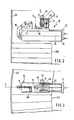
- FIG. 1 shows a grapple 10 according to the present invention mounted at the end of an arm 8 of a robot or other handling machine.
- the grapple 10 comprises a plate 12 which, in the embodiment shown, has a rectangular shape, and which is provided, on the two opposite short sides, with two claws 14,16 for holding an object, in this case two bricks superimposed, 18.20.
- the end of the arm 8 is designed, for example, in the form of a fork with two branches 8a, 8b, the branch 8b being shown only partially so as not to hide other elements.
- the grapple 10 is mounted between these two branches 8a, 8b using a cradle 22 consisting of a section 24 having a "U" shaped section with two lateral flanks, of which only the side 26 is visible, the other side, opposite side 26 being identical to the latter has not been shown so as not to overload the drawings.
- the sidewalls 26 are pivotally mounted between the branches 8a and 8b by means of pivots 28.
- One of these pivots 28 forms part of the axis of a motor, for example an electric motor 30 step by step in order to be able to rotate the cradle 22 around the axis of this suspension pivot 28.
- the motor 30 comprises a feeler for measuring the angular position of the cradle 22 and of the plate 10 relative to an axis or a reference plane, by example, the longitudinal axis of the arm 8.
- a housing 32 Between the two sides 26 of the cradle 22 is a housing 32 provided with a flange 34 held by two rods 36, 38 between the two branches of the section 24 of the cradle 22.
- a motor 40 for example an electric motor or a jack, allows movement of the flange 34 and of the casing 32 along the rods 36, 38 inside the section 24 of the cradle 22. This movement of the housing 32 perpendicular to the pivot axis 28 is controlled by a feeler 42.
- the mounting is preferably such that the central axis of the cylindrical housing 32 is perpendicular to the pivot axis 28.
- This connecting rod 46 can be turned around the vertical axis Y1 of the casing 32 by means of a motor 48 (see also FIG. 2) mounted on the casing 32 and associated with a feeler not shown to measure and control the rotation of the rod 46 around the axis of the housing 32.
- the plate 12 is pivotally mounted at the end of the horizontal branch of the connecting rod 46 so as to be able to rotate relative to the connecting rod 46 about an axis Y2 parallel to the axis of rotation of the connecting rod 46 in the housing 32.
- This pivoting of the plate 12 relative to the connecting rod 46 is measured and controlled by a probe 50.
- This possibility of pivoting can however be hampered by two small jacks 52, 54 secured to the connecting rod 46, the rods, when they come out, bear on a crosspiece 56 secured to the plate 12.
- the plate 12 thus has, when the rods of the cylinders 52 and 54 are retracted, four degrees of freedom relative to the arm 8, namely two axes Y1, Y2 of pivoting parallel perpendicular to the surface of the plate, a horizontal pivot axis and constituted by the suspension 28 in the branches 8a and 8b as well as the possibility of displacement perpendicularly with respect to its main surface under the action of the jack 40.
- the pivoting claw 16 comprises a main arm 58 mounted by means of two pivoting levers 60, 62 on the plate 12.
- the end of the arm 58 carries a pivoting jaw 64 making it possible to grasp two superimposed bricks.
- This jaw has, on the inner side, contact probes not shown.
- the claw 16 is actuated by means of a motor 68, for example electric acting on one of the levers, in this case the lever 60 to move the jaw between a closed position and an open position (see Figure 4).
- the presence of the two pivoting levers 60, 62 makes it possible to superimpose on the rotational movement a translational movement in order to reduce the space necessary for the opening of the claw 16 and thus to be able to advance the bricks 18 and 20 as close as possible to 'a wall as shown in Figure 4.
- the second claw 14 which is a sliding claw, is essentially constituted by a flat jaw 70 fixed on rods 72, 74 which can slide longitudinally in the plate 12 under the action of a motor or a jack 76.
- the action of this motor or jack 76 is also under the control of a position probe 78.
- the jaw 70 is provided with two contact probes 80 and 82, controlling the correct closing of the sliding claw 14.
- the two prongs 14 and 16 can be replaced easily and quickly by corresponding prongs which are designed only for gripping a single brick, if necessary.
- the plate 12 further comprises at least on one of the longitudinal sides, at least one, preferably two positioning segments 84,86.
- These segments 84,86 are mounted on the rods 72 and / or 74 for supporting the sliding claw 14 and can be moved longitudinally with the latter.
- the segments 84 and 86 are, moreover, pivotally mounted on these rods so that they can be moved, under the action of automatic means not shown between the position shown in FIG. 1 and a horizontal position along the flank of the plate 12
- the segments 84,86 are, like all the moving parts of the grapple 10, provided with feelers 88,90,92,94 to check the correct positioning of the plate relative to the bricks 18,20 and vice versa.
- the grab 10 is also provided with a radiation rangefinder 96, known per se, for measuring the distance separating the grab from a wall, for example, from the wall of the converter.
- This rangefinder 96 operates with a diverging beam as opposed to a point source which, aiming at a point on a surface can cause errors if this surface is not very smooth. This distance can also be measured using a mechanical contact probe.
- the robot automatically brings the bricks into the position of Figure 2 from pallets located on a platform of an operating station in the converter, not shown in the figure.
- the robot is programmed by computer, according to the location of the pallets and the arrangement of the bricks on them in order to go and get them automatically and according to a predetermined depalletization program.
- the robot is also programmed to automatically choose between the two pallets, to take the right type of bricks, this according to the measurements made during previous poses.
- the grapple 10 is positioned so as to grip a pair of superimposed bricks, the claw 16 being in the closed position, while the claw 14 is sufficiently extended so that the plate 12 of the grapple 10 can be lowered onto the upper brick .
- the sliding claw 14 is retracted until its feelers 80 and 82 detect contact with each of the bricks. The claw 14 is then retracted further, the grapple 10 remaining stationary.
- the two bricks are moved in the direction of the jaw 64 of the claw 16 and are detached from the brick below if they were glued to it before.
- the sliding claw 14 is automatically stopped when each of the two feelers provided in the jaw 64 of the claw 16 signals the contact with each of the bricks.
- Another possibility of detaching the bricks is to increase the mass of the claw 14, in order to produce, when it is closed, a shock effect which detaches the one or two upper bricks as a result of the inertia of the lower brick.
- Another possibility, which can possibly be combined with one of those mentioned above, is to provide the claw 14 with a vibrator.
- the functions of depalletizing and transporting the bricks have been separated, on the one hand, and the placing of the bricks, on the other hand.
- the arm 12 of the robot brings the bricks automatically to a well-determined reference point from which the positioning is taken over by the grapple 10 which performs most of the movements relative to this reference point.
- This reference point can for example be the point O represented in FIG. 2 and which constitutes the intersection between the horizontal suspension axis between the branches 8a and 8b of the arm 8 and the vertical pivot axis of the connecting rod 46 in the housing 32.
- This reference point O will be at predetermined distances from the wall 98, from the upper surface of the covering 100 already laid, as well as from the brick or from the pair of neighboring bricks 102 previously deposited.
- the distance from the wall 98 will be determined so that the pivoting claw 16 can be opened.
- the vertical distance from the upper surface of the covering 100 will be determined so that the height separating this surface from the lower brick 18 is less than the thickness of a brick to prevent the upper brick 20 from catching on the neighboring brick 102 during the descent and when the upper brick 20 is not perfectly positioned on the lower brick 18.
- the reference point O thus determined is recalculated after each laying of a pair of bricks, in particular as a function of the measurements provided by the positioning probes and of the type of bricks laid.
- the robot control program takes these corrections into account in order to bring the gripper 10 each time into the reference position thus calculated.
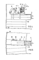
- Figures 2 and 3 show the grapple 10 with a pair of bricks 18, 20 occupying the reference position, respectively in elevation and in plan.
- the median longitudinal axis represented by X in FIG. 3 passes approximately through the non-visible vertical central axis of the converter.
- the first phase consists in actuating the motor 48 to rotate the connecting rod 46 anticlockwise as seen in FIG. 3.
- the plate 12 being blocked by the jacks 52 and 54 relative to the connecting rod 46, that -this rotates the plate 12 with the bricks around the vertical axis Y1 until the outer corner of the bricks comes into contact with the neighboring brick 102.
- the amplitude of this pivoting until contact with the neighboring brick 102 is measured by the probe associated with the motor 48.
- the resistance to continued pivoting is automatically detected by the motor 48 and controls the withdrawal of the rods from the jacks 52 and 54 to release the pivot axis between the plate 12 and the connecting rod 46 represented by Y2 in FIGS. 2 and 3.
- the continuation of the pivoting of the connecting rod 46 under the action of the motor 48 generates, consequently, a rotation of the plate and the bricks in a clockwise direction around the vertical axis Y2 until the two bricks 18 and 20 touch the entire neighboring brick 102 over the entire length.
- the amplitude of pivoting of this second phase around Y2 detected by the probe 50 must theoretically correspond approximately to the amplitude of the pivoting of the first phase around the Y1 axis.
- the grapple 10 After having thus been moved laterally against the brick 102, the grapple 10 is lowered onto the surface of the covering 100 under the action of the motor 40. As soon as the bricks are supported on the covering 100, which is automatically detected by the motor 40, the pivoting claw 16 is opened under the action of the motor 68 as shown in FIG. 4. At this stage, it is planned to lower the segments 84, 86 which, until now, were in the raised position along of the plate 12. However, it is not certain that these segments can be folded down to the position shown in Figure 1 because it is possible that, when taking the bricks 18 and 20 on the pallet, these were gripped so that the upper edge of the brick 20 exceeds the longitudinal edge of the plate 12 on the side of the segments 84 and 86.
- the plate freed from the bricks by the 'opening of the claws, is first pivoted slightly clockwise in Figures 3 and 5 by rotating the connecting rod in the opposite direction to its previous rotation. After the segments 84 and 86 have been folded back into the position shown in FIG. 1, the plate 12 is again pivoted, under the action of the motor 48 and of the connecting rod 46 anticlockwise in the figure. 5 until the segments 84 and 86 are in contact with the lateral sides of the bricks 18 and 20, which is detected by the probes 88, 90, 92 and 94.
- the motor 76 is actuated to return the sliding claw 14 into the plate 12 and push the two bricks 18 and 20 against the wall 98.
- the two segments 84 and 86 which advance with the sliding claw 14 must guide the two bricks and keep them during this sliding contact previously established with the neighboring brick 102.
- the two bricks are advanced in this way until they occupy the final position either against the wall 98, or at a certain distance from this one.
- the amplitude of the movement of the sliding clamp 14 should, in theory, always be the same, the path traveled being controlled by the probe 78 which automatically controls the stopping of the motor 76 according to the initial program.
- the rangefinder 97 measures, when the bricks are pushed towards the wall, the distance separating the bricks of the wall and thus controls the approximation thereof. The rangefinder 96 can thus command the premature stop of the motor 76 if the bricks were in the final position before the position fixed by the program.
- the rangefinder 96 can control the continuation of the movement of the clamp 14 and transmit corresponding information to the central unit to modify the calculation of the reference point accordingly for the next pose.
- the robot returns to the pallets to take a new pair of bricks.
- the claw 16 is closed while the claw 14 is opened by releasing the plate 12.
- a cleaning device for example a suction or blower with or without brushes and which is actuated as soon as the grapple has reached its reference point or already during the approach.
Landscapes
- Engineering & Computer Science (AREA)
- Robotics (AREA)
- Mechanical Engineering (AREA)
- Chemical & Material Sciences (AREA)
- Manufacturing & Machinery (AREA)
- Materials Engineering (AREA)
- Metallurgy (AREA)
- Organic Chemistry (AREA)
- Manipulator (AREA)
- Furnace Housings, Linings, Walls, And Ceilings (AREA)
- Carbon Steel Or Casting Steel Manufacturing (AREA)
- Stacking Of Articles And Auxiliary Devices (AREA)
Priority Applications (1)
| Application Number | Priority Date | Filing Date | Title |
|---|---|---|---|
| AT86116249T ATE50937T1 (de) | 1985-12-03 | 1986-11-24 | Automatischer greifer zum handhaben von gegenstaenden und ein mit diesem greifer versehener roboter. |
Applications Claiming Priority (2)
| Application Number | Priority Date | Filing Date | Title |
|---|---|---|---|
| LU86188 | 1985-12-03 | ||
| LU86188A LU86188A1 (fr) | 1985-12-03 | 1985-12-03 | Grappin automatique de manutention d'objets et robot pourvu d'un tel grappin |
Publications (2)
| Publication Number | Publication Date |
|---|---|
| EP0226076A1 true EP0226076A1 (de) | 1987-06-24 |
| EP0226076B1 EP0226076B1 (de) | 1990-03-14 |
Family
ID=19730591
Family Applications (1)
| Application Number | Title | Priority Date | Filing Date |
|---|---|---|---|
| EP86116249A Expired - Lifetime EP0226076B1 (de) | 1985-12-03 | 1986-11-24 | Automatischer Greifer zum Handhaben von Gegenständen und ein mit diesem Greifer versehener Roboter |
Country Status (7)
| Country | Link |
|---|---|
| US (1) | US4758036A (de) |
| EP (1) | EP0226076B1 (de) |
| JP (1) | JPS62134488A (de) |
| AT (1) | ATE50937T1 (de) |
| DE (1) | DE3669452D1 (de) |
| ES (1) | ES2013709B3 (de) |
| LU (1) | LU86188A1 (de) |
Cited By (3)
| Publication number | Priority date | Publication date | Assignee | Title |
|---|---|---|---|---|
| EP0432565A1 (de) * | 1989-12-11 | 1991-06-19 | Leifeld und Lemke Maschinenfabrik GmbH | Vorrichtung zum Stapeln bzw. Entstapeln |
| EP0477661A1 (de) * | 1990-09-26 | 1992-04-01 | Arbed S.A. | Vorrichtung zur automatischen Handhabung von Gegenständen |
| EP0860356A1 (de) * | 1997-02-25 | 1998-08-26 | Cat System S.r.l. | Vorrichtung zum Stellen von Gruppen von Gegenständen auf Paletten |
Families Citing this family (19)
| Publication number | Priority date | Publication date | Assignee | Title |
|---|---|---|---|---|
| LU87381A1 (fr) * | 1988-11-09 | 1990-06-12 | Wurth Paul Sa | Installation automatisee pour la pose d'une maconnerie sur une paroi |
| US5102280A (en) | 1989-03-07 | 1992-04-07 | Ade Corporation | Robot prealigner |
| US5489184A (en) * | 1994-09-13 | 1996-02-06 | Westinghouse Electric Corporation | Pellet loader |
| ITMO20020050A1 (it) * | 2002-02-28 | 2003-08-28 | Ferrari & Cigarini Srl | Dispositivo per la depalletizzazione di pacchi di piastrelle |
| US8965571B2 (en) | 2010-08-12 | 2015-02-24 | Construction Robotics, Llc | Brick laying system |
| JP6245218B2 (ja) * | 2015-01-29 | 2017-12-13 | Jfeスチール株式会社 | コークス炉定型耐火物積みシステムおよびコークス炉定型耐火物積み方法 |
| JP6471721B2 (ja) * | 2016-04-20 | 2019-02-20 | Jfeスチール株式会社 | コークス炉用定型耐火物把持装置およびコークス炉用定型耐火物把持方法 |
| ES2899585T3 (es) | 2016-07-15 | 2022-03-14 | Fastbrick Ip Pty Ltd | Pluma para transporte de material |
| JP7061119B2 (ja) | 2016-07-15 | 2022-04-27 | ファストブリック・アイピー・プロプライエタリー・リミテッド | 車両に組み込まれた煉瓦/ブロック敷設機 |
| CN111095355B (zh) | 2017-07-05 | 2023-10-20 | 快砖知识产权私人有限公司 | 实时定位和定向跟踪器 |
| US11958193B2 (en) | 2017-08-17 | 2024-04-16 | Fastbrick Ip Pty Ltd | Communication system for an interaction system |
| AU2018317941B2 (en) | 2017-08-17 | 2023-11-09 | Fastbrick Ip Pty Ltd | Laser tracker with improved roll angle measurement |
| CN111212799B (zh) | 2017-10-11 | 2023-04-14 | 快砖知识产权私人有限公司 | 用于传送物体的机器以及与其一起使用的多隔间转盘 |
| CN108149934B (zh) * | 2017-12-20 | 2024-01-26 | 孙清鹏 | 路砖夹取铺设器及其使用方法 |
| WO2020014737A1 (en) | 2018-07-16 | 2020-01-23 | Fastbrick Ip Pty Ltd | Backup tracking for an interaction system |
| US12311546B2 (en) | 2018-07-16 | 2025-05-27 | Fastbrick Ip Pty Ltd | Active damping system |
| CN110640760A (zh) * | 2019-10-08 | 2020-01-03 | 苏州恒地智能科技有限公司 | 一种半自动机械手装置 |
| CN115443363A (zh) | 2020-04-22 | 2022-12-06 | 快砖知识产权私人有限公司 | 块传送装置及用于与其一起使用的改进的夹紧组件 |
| AU2021304545B2 (en) | 2020-07-08 | 2025-12-04 | Fastbrick Ip Pty Ltd | Adhesive application system |
Citations (6)
| Publication number | Priority date | Publication date | Assignee | Title |
|---|---|---|---|---|
| US2370528A (en) * | 1942-07-15 | 1945-02-27 | Robert A Fontaine | Material handling device |
| US3586176A (en) * | 1969-04-09 | 1971-06-22 | George C Devol | Palletizing apparatus |
| FR2070868A1 (de) * | 1969-12-15 | 1971-09-17 | Koninkl Nederland Ch | |
| EP0001686A1 (de) * | 1977-10-20 | 1979-05-02 | Imperial Chemical Industries Plc | Industrieller Manipulator zum dicht gegeneinander Stapeln von Gegenständen und Stapelnverfahren unter Verwendung des Manipulators |
| GB2129086A (en) * | 1982-10-26 | 1984-05-10 | Marconi Co Ltd | Co-ordinate tables |
| DE3312483A1 (de) * | 1983-04-07 | 1984-10-11 | Blohm + Voss Ag, 2000 Hamburg | Greifer fuer industrieroboter |
Family Cites Families (4)
| Publication number | Priority date | Publication date | Assignee | Title |
|---|---|---|---|---|
| US3604745A (en) * | 1969-06-23 | 1971-09-14 | Anderson Clayton & Co | Toggle arm clamp for lift trucks |
| US4254984A (en) * | 1978-04-05 | 1981-03-10 | Imc-Carver Foundry Products, Inc. | Mold handler |
| US4318562A (en) * | 1980-03-03 | 1982-03-09 | Libbey-Owens-Ford Company | Grasping apparatus for handling heated articles |
| US4533167A (en) * | 1984-02-13 | 1985-08-06 | Honeywell Inc. | Robotics manipulator with gripping force control means |
-
1985
- 1985-12-03 LU LU86188A patent/LU86188A1/fr unknown
-
1986
- 1986-11-24 AT AT86116249T patent/ATE50937T1/de not_active IP Right Cessation
- 1986-11-24 EP EP86116249A patent/EP0226076B1/de not_active Expired - Lifetime
- 1986-11-24 ES ES86116249T patent/ES2013709B3/es not_active Expired - Lifetime
- 1986-11-24 DE DE8686116249T patent/DE3669452D1/de not_active Expired - Lifetime
- 1986-12-01 JP JP61286559A patent/JPS62134488A/ja active Pending
- 1986-12-03 US US06/937,646 patent/US4758036A/en not_active Expired - Fee Related
Patent Citations (6)
| Publication number | Priority date | Publication date | Assignee | Title |
|---|---|---|---|---|
| US2370528A (en) * | 1942-07-15 | 1945-02-27 | Robert A Fontaine | Material handling device |
| US3586176A (en) * | 1969-04-09 | 1971-06-22 | George C Devol | Palletizing apparatus |
| FR2070868A1 (de) * | 1969-12-15 | 1971-09-17 | Koninkl Nederland Ch | |
| EP0001686A1 (de) * | 1977-10-20 | 1979-05-02 | Imperial Chemical Industries Plc | Industrieller Manipulator zum dicht gegeneinander Stapeln von Gegenständen und Stapelnverfahren unter Verwendung des Manipulators |
| GB2129086A (en) * | 1982-10-26 | 1984-05-10 | Marconi Co Ltd | Co-ordinate tables |
| DE3312483A1 (de) * | 1983-04-07 | 1984-10-11 | Blohm + Voss Ag, 2000 Hamburg | Greifer fuer industrieroboter |
Non-Patent Citations (2)
| Title |
|---|
| IBM TECHNICAL DISCLOSURE BULLETIN, vol. 27, no. 7B, décembre 1984, pages 4294-4295, New York, US; R.L. KAFTAN et al.: "Gripper with integral parts transfer" * |
| IBM TECHNICAL DISCLOSURE BULLETIN, vol. 28, no. 7, décembre 1985, pages 2992-2997, New York, US; "End effector with diagonal and rotational compliance mechanism" * |
Cited By (5)
| Publication number | Priority date | Publication date | Assignee | Title |
|---|---|---|---|---|
| EP0432565A1 (de) * | 1989-12-11 | 1991-06-19 | Leifeld und Lemke Maschinenfabrik GmbH | Vorrichtung zum Stapeln bzw. Entstapeln |
| EP0477661A1 (de) * | 1990-09-26 | 1992-04-01 | Arbed S.A. | Vorrichtung zur automatischen Handhabung von Gegenständen |
| TR25348A (tr) * | 1990-09-26 | 1993-03-01 | Wurth Paul Sa | CISIMLERIN OTOMATIK SEKILDE YERLESTIRILMELERINI SAGLAYAN DüZEN |
| EP0860356A1 (de) * | 1997-02-25 | 1998-08-26 | Cat System S.r.l. | Vorrichtung zum Stellen von Gruppen von Gegenständen auf Paletten |
| US6238173B1 (en) | 1997-02-25 | 2001-05-29 | Cat System S.R.L. | Apparatus for placing groups of products on pallets |
Also Published As
| Publication number | Publication date |
|---|---|
| US4758036A (en) | 1988-07-19 |
| DE3669452D1 (de) | 1990-04-19 |
| EP0226076B1 (de) | 1990-03-14 |
| LU86188A1 (fr) | 1987-07-24 |
| JPS62134488A (ja) | 1987-06-17 |
| ATE50937T1 (de) | 1990-03-15 |
| ES2013709B3 (es) | 1990-06-01 |
Similar Documents
| Publication | Publication Date | Title |
|---|---|---|
| EP0226076B1 (de) | Automatischer Greifer zum Handhaben von Gegenständen und ein mit diesem Greifer versehener Roboter | |
| EP0392926B1 (de) | Telemanipulator, vorgesehen zum Aufhängen an einem Hebezeug | |
| BE1006857A3 (fr) | Installation pour garnir d'une maconnerie de briques une paroi interieure d'une enceinte. | |
| FR2583727A1 (fr) | Appareil de positionnement et chargeur pour dispositif transporteur utilisable notamment pour des isolateurs de bougies d'allumage avant frittage. | |
| FR2541920A1 (fr) | Manipulateur a bras telescopique | |
| CH652954A5 (fr) | Appareil pour prelever des pieces en forme de tiges ou baguettes a partir d'une pile de telles pieces. | |
| FR2494617A1 (fr) | Robot universel | |
| EP4204332B1 (de) | Container-display-station | |
| EP0248251B1 (de) | Automatisierte Vorrichtung zum Ausmauern eines Gefässes | |
| EP4551486A1 (de) | Palettierungsanlage | |
| EP3520957B1 (de) | Fördervorrichtung für auf paletten gelagerten teilen, die in der nähe eines verabeitungszentrums positionierbar ist | |
| EP3750841A1 (de) | Vorrichtung zur handhabung eines starren panels und handhabungsverfahren mit solchen vorrichtung | |
| FR3125452A1 (fr) | Outil de préhension de caisse et système de palettisation et/ou de dépalettisation le comprenant | |
| FR2699836A1 (fr) | Procédé et dispositif de tri automatique de pastilles de combustible nucléaire. | |
| EP0477661A1 (de) | Vorrichtung zur automatischen Handhabung von Gegenständen | |
| EP0425331B1 (de) | Vorrichtung zum Entleeren durch Untertauchen von Kästen, welche schwimmfähige Gegenstände enthalten, insbesondere Obst | |
| FR2747660A1 (fr) | Dispositif pour saisir et manipuler des charges | |
| EP3179194A1 (de) | Haltevorrichtung einer granate für artilleriewaffe | |
| WO2021229092A1 (fr) | Dispositif d'interface pour bras rotatif robotisé, procédé de commande, dispositif d'intervention | |
| EP0855251A1 (de) | Gestell für Verkleidung von Sofas oder dergleichen | |
| FR2599994A1 (fr) | Procede et dispositif de selection et de manipulation d'objets parmi une collection de ceux-ci | |
| EP0262003B1 (de) | Einrichtung zur Kontrolle und Behandlung von Gegenständen | |
| FR2731979A1 (fr) | Dispositif de vidange par immersion dans une cuve contenant un liquide d'au moins une caisse contenant des produits flottants | |
| EP0329527A1 (de) | Zu- und Abführvorrichtung der Werkzeuge einer vertikalen Räummaschine | |
| FR2491891A1 (fr) | Procede de manutention et de stockage d'objets a symetrie axiale, notamment de tourets et dispositif trans-stockeur de mise en oeuvre |
Legal Events
| Date | Code | Title | Description |
|---|---|---|---|
| PUAI | Public reference made under article 153(3) epc to a published international application that has entered the european phase |
Free format text: ORIGINAL CODE: 0009012 |
|
| AK | Designated contracting states |
Kind code of ref document: A1 Designated state(s): AT BE DE ES FR GB IT NL SE |
|
| 17P | Request for examination filed |
Effective date: 19871029 |
|
| 17Q | First examination report despatched |
Effective date: 19881024 |
|
| GRAA | (expected) grant |
Free format text: ORIGINAL CODE: 0009210 |
|
| AK | Designated contracting states |
Kind code of ref document: B1 Designated state(s): AT BE DE ES FR GB IT NL SE |
|
| REF | Corresponds to: |
Ref document number: 50937 Country of ref document: AT Date of ref document: 19900315 Kind code of ref document: T |
|
| GBT | Gb: translation of ep patent filed (gb section 77(6)(a)/1977) | ||
| REF | Corresponds to: |
Ref document number: 3669452 Country of ref document: DE Date of ref document: 19900419 |
|
| ITF | It: translation for a ep patent filed | ||
| PLBE | No opposition filed within time limit |
Free format text: ORIGINAL CODE: 0009261 |
|
| STAA | Information on the status of an ep patent application or granted ep patent |
Free format text: STATUS: NO OPPOSITION FILED WITHIN TIME LIMIT |
|
| 26N | No opposition filed | ||
| ITTA | It: last paid annual fee | ||
| PGFP | Annual fee paid to national office [announced via postgrant information from national office to epo] |
Ref country code: SE Payment date: 19920714 Year of fee payment: 7 |
|
| PGFP | Annual fee paid to national office [announced via postgrant information from national office to epo] |
Ref country code: FR Payment date: 19921007 Year of fee payment: 7 |
|
| PGFP | Annual fee paid to national office [announced via postgrant information from national office to epo] |
Ref country code: BE Payment date: 19921021 Year of fee payment: 7 |
|
| PGFP | Annual fee paid to national office [announced via postgrant information from national office to epo] |
Ref country code: DE Payment date: 19921102 Year of fee payment: 7 |
|
| PGFP | Annual fee paid to national office [announced via postgrant information from national office to epo] |
Ref country code: GB Payment date: 19921104 Year of fee payment: 7 |
|
| PGFP | Annual fee paid to national office [announced via postgrant information from national office to epo] |
Ref country code: ES Payment date: 19921118 Year of fee payment: 7 |
|
| PGFP | Annual fee paid to national office [announced via postgrant information from national office to epo] |
Ref country code: AT Payment date: 19921126 Year of fee payment: 7 |
|
| PGFP | Annual fee paid to national office [announced via postgrant information from national office to epo] |
Ref country code: NL Payment date: 19921130 Year of fee payment: 7 |
|
| PG25 | Lapsed in a contracting state [announced via postgrant information from national office to epo] |
Ref country code: GB Effective date: 19931124 Ref country code: AT Effective date: 19931124 |
|
| PG25 | Lapsed in a contracting state [announced via postgrant information from national office to epo] |
Ref country code: SE Effective date: 19931125 Ref country code: ES Free format text: LAPSE BECAUSE OF NON-PAYMENT OF DUE FEES Effective date: 19931125 |
|
| PG25 | Lapsed in a contracting state [announced via postgrant information from national office to epo] |
Ref country code: BE Effective date: 19931130 |
|
| BERE | Be: lapsed |
Owner name: S.A. PAUL WURTH Effective date: 19931130 |
|
| PG25 | Lapsed in a contracting state [announced via postgrant information from national office to epo] |
Ref country code: NL Effective date: 19940601 |
|
| NLV4 | Nl: lapsed or anulled due to non-payment of the annual fee | ||
| GBPC | Gb: european patent ceased through non-payment of renewal fee |
Effective date: 19931124 |
|
| PG25 | Lapsed in a contracting state [announced via postgrant information from national office to epo] |
Ref country code: FR Effective date: 19940729 |
|
| PG25 | Lapsed in a contracting state [announced via postgrant information from national office to epo] |
Ref country code: DE Effective date: 19940802 |
|
| REG | Reference to a national code |
Ref country code: FR Ref legal event code: ST |
|
| EUG | Se: european patent has lapsed |
Ref document number: 86116249.3 Effective date: 19940610 |
|
| REG | Reference to a national code |
Ref country code: ES Ref legal event code: FD2A Effective date: 19941214 |
|
| PG25 | Lapsed in a contracting state [announced via postgrant information from national office to epo] |
Ref country code: IT Free format text: LAPSE BECAUSE OF NON-PAYMENT OF DUE FEES;WARNING: LAPSES OF ITALIAN PATENTS WITH EFFECTIVE DATE BEFORE 2007 MAY HAVE OCCURRED AT ANY TIME BEFORE 2007. THE CORRECT EFFECTIVE DATE MAY BE DIFFERENT FROM THE ONE RECORDED. Effective date: 20051124 |