EP0226216A2 - Destilliervorrichtung - Google Patents
Destilliervorrichtung Download PDFInfo
- Publication number
- EP0226216A2 EP0226216A2 EP86117607A EP86117607A EP0226216A2 EP 0226216 A2 EP0226216 A2 EP 0226216A2 EP 86117607 A EP86117607 A EP 86117607A EP 86117607 A EP86117607 A EP 86117607A EP 0226216 A2 EP0226216 A2 EP 0226216A2
- Authority
- EP
- European Patent Office
- Prior art keywords
- vapor
- raw water
- porous film
- hydrophobic porous
- water
- Prior art date
- Legal status (The legal status is an assumption and is not a legal conclusion. Google has not performed a legal analysis and makes no representation as to the accuracy of the status listed.)
- Granted
Links
Images

Classifications
-
- C—CHEMISTRY; METALLURGY
- C02—TREATMENT OF WATER, WASTE WATER, SEWAGE, OR SLUDGE
- C02F—TREATMENT OF WATER, WASTE WATER, SEWAGE, OR SLUDGE
- C02F1/00—Treatment of water, waste water, or sewage
- C02F1/02—Treatment of water, waste water, or sewage by heating
- C02F1/04—Treatment of water, waste water, or sewage by heating by distillation or evaporation
- C02F1/045—Treatment of water, waste water, or sewage by heating by distillation or evaporation for obtaining ultra-pure water
-
- B—PERFORMING OPERATIONS; TRANSPORTING
- B01—PHYSICAL OR CHEMICAL PROCESSES OR APPARATUS IN GENERAL
- B01D—SEPARATION
- B01D1/00—Evaporating
- B01D1/30—Accessories for evaporators ; Constructional details thereof
-
- B—PERFORMING OPERATIONS; TRANSPORTING
- B01—PHYSICAL OR CHEMICAL PROCESSES OR APPARATUS IN GENERAL
- B01D—SEPARATION
- B01D3/00—Distillation or related exchange processes in which liquids are contacted with gaseous media, e.g. stripping
- B01D3/06—Flash distillation
-
- B—PERFORMING OPERATIONS; TRANSPORTING
- B01—PHYSICAL OR CHEMICAL PROCESSES OR APPARATUS IN GENERAL
- B01D—SEPARATION
- B01D5/00—Condensation of vapours; Recovering volatile solvents by condensation
- B01D5/0003—Condensation of vapours; Recovering volatile solvents by condensation by using heat-exchange surfaces for indirect contact between gases or vapours and the cooling medium
- B01D5/0006—Coils or serpentines
-
- B—PERFORMING OPERATIONS; TRANSPORTING
- B01—PHYSICAL OR CHEMICAL PROCESSES OR APPARATUS IN GENERAL
- B01D—SEPARATION
- B01D5/00—Condensation of vapours; Recovering volatile solvents by condensation
- B01D5/0057—Condensation of vapours; Recovering volatile solvents by condensation in combination with other processes
- B01D5/006—Condensation of vapours; Recovering volatile solvents by condensation in combination with other processes with evaporation or distillation
-
- B—PERFORMING OPERATIONS; TRANSPORTING
- B01—PHYSICAL OR CHEMICAL PROCESSES OR APPARATUS IN GENERAL
- B01D—SEPARATION
- B01D5/00—Condensation of vapours; Recovering volatile solvents by condensation
- B01D5/0078—Condensation of vapours; Recovering volatile solvents by condensation characterised by auxiliary systems or arrangements
- B01D5/009—Collecting, removing and/or treatment of the condensate
-
- B—PERFORMING OPERATIONS; TRANSPORTING
- B01—PHYSICAL OR CHEMICAL PROCESSES OR APPARATUS IN GENERAL
- B01D—SEPARATION
- B01D61/00—Processes of separation using semi-permeable membranes, e.g. dialysis, osmosis or ultrafiltration; Apparatus, accessories or auxiliary operations specially adapted therefor
- B01D61/36—Pervaporation; Membrane distillation; Liquid permeation
- B01D61/364—Membrane distillation
-
- Y—GENERAL TAGGING OF NEW TECHNOLOGICAL DEVELOPMENTS; GENERAL TAGGING OF CROSS-SECTIONAL TECHNOLOGIES SPANNING OVER SEVERAL SECTIONS OF THE IPC; TECHNICAL SUBJECTS COVERED BY FORMER USPC CROSS-REFERENCE ART COLLECTIONS [XRACs] AND DIGESTS
- Y10—TECHNICAL SUBJECTS COVERED BY FORMER USPC
- Y10S—TECHNICAL SUBJECTS COVERED BY FORMER USPC CROSS-REFERENCE ART COLLECTIONS [XRACs] AND DIGESTS
- Y10S159/00—Concentrating evaporators
- Y10S159/27—Micropores
-
- Y—GENERAL TAGGING OF NEW TECHNOLOGICAL DEVELOPMENTS; GENERAL TAGGING OF CROSS-SECTIONAL TECHNOLOGIES SPANNING OVER SEVERAL SECTIONS OF THE IPC; TECHNICAL SUBJECTS COVERED BY FORMER USPC CROSS-REFERENCE ART COLLECTIONS [XRACs] AND DIGESTS
- Y10—TECHNICAL SUBJECTS COVERED BY FORMER USPC
- Y10S—TECHNICAL SUBJECTS COVERED BY FORMER USPC CROSS-REFERENCE ART COLLECTIONS [XRACs] AND DIGESTS
- Y10S159/00—Concentrating evaporators
- Y10S159/28—Porous member
Definitions
- the present invention relates to a distilling apparatus which is adapted to obtain extremely pure distilled water containing a very small amount of impurities from raw water.
- Distilled water of a high purity (also called “ultrapure water") which contains a very small amount of impurities is conventionally demanded by the electronics industry for manufacturing semiconductors and the pharmaceutical industry for manufacturing pharmaceutical substances.
- heated raw water is supplied to a hydrophobic porous film and is brought into contact therewith, and vapor generated from the raw water filters through the hydrophobic porous film.
- the raw water is directly supplied to one surface of the hydrophobic porous film, the proportion of vapor generated on the side of that surface is small, thus making it difficult for a large amount of vapor to filter through the film.
- the hydrophobic porous film has a large number of small holes formed therein, and vapor which is generated from the surface of the raw water, which is in a state wherein it slightly penetrates the holes, filters therethrough. Thereafter, the filtered vapor is condensed by means of cooling water so as to obtain distilled water.
- gases e.g., carbonic dioxide gas and oxygen gas
- volatile substances which are dissolved in the raw water also evaporate and pass through the film. Therefore, the gases and volatile substances are dissolved in the condensed product, thus impeding the effort of increasing the degree of purity. In conventional apparatuses, no particular attention has been paid to this problem.
- One example of the prior art relating to this type of apparatus is that disclosed in U.S.P. No. 3,563,860.
- An object of the invention is to provide a distilling apparatus which is capable of obtaining a large amount of distilled water from raw water at a high degree of efficiency.
- Another object of the invention is to provide a distilling apparatus which is capable of obtaining extremely pure distilled water.
- a further object of the invention is to provide a distilling apparatus which is designed to reduce its energy consumption.
- a distilling apparatus provided with an evaporation section which heats raw water and causes the generation of vapor from the raw water, a hydrophobic porous film through which the thus generated vapor is filtered, and a condensation section which allows the condensation of the thus filtered vapor; wherein the evaporation section for causing the generation of the vapor and the hydrophobic porous film located downstream thereof are separately provided, and the vapor filtered through the film is allowed to condense.
- the apparatus comprises a main distilling apparatus body 50, a heater l0, a recirculation pump 20, and a heat economizer 35.
- the main body 50 is divided into an evaporation chamber 5l and condensation chamber 52 by a hydrophobic porous film 30.
- a nozzle 60 which discharges heated raw water l00 is disposed in the evaporation chamber 5l whose bottom forms a raw water tank 6l.
- a cooling pipe 80 is disposed in the condensation chamber 52 whose bottom is formed into a distilled water tank 8l.
- the raw water l00 is introduced into the heat economizer 35 wherein it exchanges heat with distilled water 500 and is heated thereby, and is then led to the heater l0 through the pump 20 to be heated.
- the raw water l00 is heated to a temperature which is a few degrees higher than the saturated vapor temperature within the evaporation chamber 5l (the difference between the water temperature and the saturated vapor temperature is called “the flash temperature” which is normally about 3 to 5°C, and the state of vapor in which it is heated to a temperature above the saturation temperature is called “the superheated state").
- the thus heated raw water l00 is discharged into the evaporation chamber 5l through the nozzle 60 and instantly self-evaporates, generating a large amount of fine water droplets. Evaporation proceeds on the surface of the water droplets, and the temperature of the droplets drops to the vapor saturation temperature within the evaporation chamber 5l. Vapor 200 generated in the chamber 5l flows into the condensation chamber 52 together with the water droplets ll0, but when they filter through the hydrophobic porous film 30, the water droplets ll0 are completely separated, so that the vapor 200 alone is introduced into the condensation chamber 52. In the chamber 52, the vapor 200 is cooled and allowed to condense on the surface of the cooling pipe 80 through which cooling water 600 flows, so as to become distilled water 500 which is collected in the distilled water tank 8l.
- the apparatus is arranged in such a manner that only vapor and water droplets which have been separated from the raw water are supplied to one surface of the hydrophobic porous film. Therefore, the proportion of vapor relative to the fluid supplied to that one surface of the film can be increased, thus enabling the efficient filtering of a large amount of the vapor through the film.
- the distilled water 500 in the distilled water tank 8l is discharged by means of a valve 40 located at a point of use and is used for washing, etc.
- a valve 40 located at a point of use and is used for washing, etc.
- the distilled water 500 stored in the tank 8l has a relatively high temperature on the order of several tens of degrees, when it is discharged from the valve 40, it is cooled by utilizing the raw water l00 in the heat economizer 35.
- the raw water l00 in the evaporation chamber 5l has a temperature on the order of l00°C, having been heated to a temperature of about l05°C by the heater l0. Because the interior of the evaporation chamber 5l is filled with the saturated vapor 200 and the water droplets ll0, the distilled water 500 within the adjacent distilled water tank 8l has a temperature of about l00°C which is the boiling point of water.
- the apparatus since the apparatus is operated at an internal temperature in the vicinity of l00°C, any bacteria and the like contained in the raw water are killed by the high temperature, thus providing a sterilization effect.
- the flash evaporation which takes place in the apparatus causes the small amounts of air and carbonic dioxide gas dissolved in the raw water to be discharged.
- the evaporation chamber 5l when the vapor evaporates from the raw water at a temperature on the order of l00°C, a small amount of volatile organic substances (which have boiling points of below l00°C) are also discharged.
- the distilled water 500 in the tank 8l has the same temperature as that within the evaporation chamber 5l, as described before, the thus discharged volatile organic substances are not readily re-absorbed by the distilled water 500.
- air and carbonic acid dissolved in the raw water and generated in the evaporation chamber 5l the air and carbonic acid are not readily dissolved in the distilled water in the tank 8l and hence are not re-absorbed. Instead, they are discharged to the outside through an exhaust valve 70.
- This exhaust valve 70 is of the check valve type which has a body whose interior is pressurized to a pressure sightly higher than that of the outside so as to prevent any backward flow of air, etc., from the otuside.
- part of the cooling water 600 may be used as the raw water.
- the distilled water tank 8l is positioned at a level higher than the valve 40 to provide a head which facilitates the discharge of distilled water 500 from the valve 40, this is not limitative. If it is necessary to discharge distilled water at a high pressure from the valve located at the point of use, a pump may be provided.
- distilled water of a high degree of purity can be obtained by a single evaporation and condensation operation; at the same time, by virtue of the phenomenon of flash evaporation and the provision of the hydrophobic porous film, extremely pure distilled water can be obtained by means of a compact apparatus with a high evaporation efficiency.
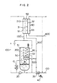
- Fig. 2 shows a second embodiment of the invention in which the heating capacity of the heater is reduced to achieve a reduction in energy consumption.
- An apparatus in accordance with this embodiment is adapted to recover the heat which is generated when vapor is, in the same way as in the embodiment shown in Fig. l, cooled and condensed by means of the cooling pipe 80, and to produce distilled water 500′ by further employing a thermobar vaporization device 90. Therefore, this device consists of only the thermobar vaporization device 90 in addition to the arrangement in accordance with the first embodiment shown in Fig. l.
- the thermobar vaporization device 90 comprises a hydrophobic porous film 3l, a cooling surface 32, a number of raw water chambers 9l, a cooling chamber 93, and an air chamber 92, the chambers being separated by the film 3l and the surface 32.
- Raw water l00 at a high temperature is introduced into the raw water chamber 9l and is supplied to a surface of the porous film 3l on which vapor 2l0 evaporates, and the vapor 2l0 thus generated from the water l00 passes through the air chamber 92 and is then cooled and condensed on the cooling surface 32, thereby producing distilled water 500′.
- the main body 50 and the thermobar vaporization device 90 are connected in the following manner.
- raw water l00′ is heated by utilizing the cooling heat obtained from the cooling pipe 80 in the condensation chamber 52 of the main body 50, and the raw water l00′ is sent to the raw water chamber 9l of the thermobar vaporization device 90 wherein the water l00′ is allowed to evaporate on the surface of the hydrophobic porous film 3l.
- Part of the raw water l00′, whose temperature is now reduced, is drained away while the remainder is returned to the cooling pipe 80 of the main body 50, in which it is heated again by the condensation heat, and is then recirculated to the raw water chamber 9l by means of the pump 20.
- the heat supplied to the apparatus is used in the flash evaporation in the main body, via the heater l0, so as to obtain distilled water 500 from the condensation of vapor resulting from the flash evaporation; and, at the same time, the condensation heat resulting from the above condensation is recovered by the cooling pipe 80 to heat the raw water l00′ which is then allowed to evaporate in the thermobar vaporization device 90 so as to obtain distilled water 500′.
- the amount of heat consumed can be reduced to a level which is about half as that with the first embodiment.
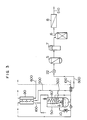
- Fig. 3 shows a distilling apparatus in accordance with a third embodiment of the invention which is adapted to perform ultra-distillation to obtain an ultra-high degree of purity (this operation is normally called "ultra-ultra distillation").
- a conventionally-known secondary pure water system is combined with the embodiment shown in Fig. 2.
- distilled water 500 obtained by the main body 50 and the thermobar vaporization device 90 is further passed by means of a pump 22 through an activated carbon absorption tower 5, an ultraviolet sterilizer 7, a polisher 6, and an ultrafilter 8.
- an activated carbon absorption tower 5 an ultraviolet sterilizer 7, a polisher 6, and an ultrafilter 8.
- the invention provides the following advantage.
- the activated carbon absorption device, the polisher, and the ultrafilter which are disposed downstream of the apparatus, need to be replaced periodically because of their limited effective life relative to their absorption and ion-exchange capacities and to the degree of clogging of the ultrafilter.
- these elements are disposed after the distilling apparatus which forms the main part of the invention, their effective life can be considerably lengthened.
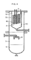
- Fig. 4 shows an example of a specific structure of the main body 50 of the distilling apparatus.
- the main apparatus body 50 has a vertical structure in which a flash evaporation nozzle 60 and a tank 6l for storing water which has not yet been evaporated are disposed in a lower portion, and a condensation chamber 52 including a hydrophobic porous film 30, a cooling pipe 80 for condensation, and a distilled water tank 8l are disposed in an upper portion.
- the main body 50 is thus adapted to achieve the advantages and effects hereinbefore described, as well as to require a minimum of mounting area.
- the nozzle 60 comprises one or more pipes which have the following dimensions determined from fundamental experiments: a diameter which is suitable for realizing a flow speed of the fluid being discharged of not more than 30 m/s., and a length of not more than 300 mm.
- the direction of the discharge is not specifically limited, it is not preferable, at least, to have it in a direction that helps to increase the speed at which the generated spray advances upward in the direction of the condensation chamber 52. In this case, it is possible to use a member for reversing the direction of advancement.
- the film 30 In order to increase the efficiency of the film 30 which is made of a hydrophobic porous material, the film 30 should have a wider area within a smaller volume. From this view point, the film 30 should preferably have a pleated structure which is disposed vertically. By virture of this structure, spray accompanying the vapor can be separated therefrom on the surface of the hydrophobic porous film 30 and can immediately drop downward in the vertical direction, and be received in the tank 6l for storing unvaporized water. Therefore, a condition which enables the filteration of the vapor can always be maintained on the surface of the hydrophobic film 30.
- the cooling pipe 80 may either be of a winding type or a straight type, but basically, an extraction pipe 7l should be disposed in a region at which the temperature is lowest in the condensation chamber 52.
- the surfaces of members which are in contact with the distilled water should have a surface roughness of not more than 0.l ⁇ m in order to prevent any microscopic retention of fluid and thus to prevent any reduction in the degree of purity. Therefore, such members should preferably be made of a material which is either SUS304 or SUS3l6, subjected to surface finishing and the formation of an oxidation film.
- the nozzle 60 and the condensation chamber 52 may be arranged in the horizontal direction.
- a large amount of vapor can be efficiently filtered through the hydrophobic porous film, whereby the efficiency of the production of ultrapure distilled water can be enhanced.
Landscapes
- Chemical & Material Sciences (AREA)
- Chemical Kinetics & Catalysis (AREA)
- Engineering & Computer Science (AREA)
- Water Supply & Treatment (AREA)
- Life Sciences & Earth Sciences (AREA)
- Hydrology & Water Resources (AREA)
- Environmental & Geological Engineering (AREA)
- Organic Chemistry (AREA)
- Heat Treatment Of Water, Waste Water Or Sewage (AREA)
- Vaporization, Distillation, Condensation, Sublimation, And Cold Traps (AREA)
- Separation Using Semi-Permeable Membranes (AREA)
Applications Claiming Priority (4)
| Application Number | Priority Date | Filing Date | Title |
|---|---|---|---|
| JP282901/85 | 1985-12-18 | ||
| JP28290185A JPS62144702A (ja) | 1985-12-18 | 1985-12-18 | 蒸留装置 |
| JP2193886A JPS62180790A (ja) | 1986-02-05 | 1986-02-05 | 超純水の製造方法 |
| JP21938/86 | 1986-02-05 |
Publications (3)
| Publication Number | Publication Date |
|---|---|
| EP0226216A2 true EP0226216A2 (de) | 1987-06-24 |
| EP0226216A3 EP0226216A3 (en) | 1988-08-03 |
| EP0226216B1 EP0226216B1 (de) | 1992-05-06 |
Family
ID=26359092
Family Applications (1)
| Application Number | Title | Priority Date | Filing Date |
|---|---|---|---|
| EP86117607A Expired EP0226216B1 (de) | 1985-12-18 | 1986-12-17 | Destilliervorrichtung |
Country Status (3)
| Country | Link |
|---|---|
| US (1) | US4953694A (de) |
| EP (1) | EP0226216B1 (de) |
| DE (1) | DE3685205D1 (de) |
Cited By (6)
| Publication number | Priority date | Publication date | Assignee | Title |
|---|---|---|---|---|
| EP0346739A3 (en) * | 1988-06-15 | 1990-06-13 | Lignyte Co., Ltd. | Method for separating a liquid component from a solution containing two or more liquid components |
| EP0284052A3 (en) * | 1987-03-25 | 1990-07-25 | Hitachi, Ltd. | Process for producing ultra-pure water and process for using said ultra-pure water |
| US7267803B2 (en) | 2000-06-19 | 2007-09-11 | Borealis Technology Oy | Degassing apparatus |
| EP1864708A1 (de) * | 2006-06-09 | 2007-12-12 | Air Products and Chemicals, Inc. | Verfahren zur Trennung von Komponenten in einem Zufuhrstrom mit mehreren Komponenten |
| CN102398895A (zh) * | 2010-09-16 | 2012-04-04 | 上海化学试剂研究所 | 一种超纯电子级化学试剂的生产方法 |
| CN107551791A (zh) * | 2017-09-30 | 2018-01-09 | 世源科技工程有限公司 | 一种废气处理设备的循环液系统及废气处理设备 |
Families Citing this family (34)
| Publication number | Priority date | Publication date | Assignee | Title |
|---|---|---|---|---|
| JP3107215B2 (ja) * | 1990-08-01 | 2000-11-06 | 株式会社日立製作所 | 蒸留装置 |
| US5268150A (en) * | 1991-12-18 | 1993-12-07 | Corning Incorporated | Concentrator/extractor apparatus having a hydrophobic membrane |
| JP2814041B2 (ja) * | 1992-10-21 | 1998-10-22 | 三菱電機株式会社 | 超純水の製造方法およびその装置 |
| DE4326842A1 (de) * | 1993-08-10 | 1995-02-16 | Matthias Mauz | Verfahren und Vorrichtung zur Abtrennung von Lösemitteln aus Fluidgemischen |
| US5496778A (en) * | 1994-01-07 | 1996-03-05 | Startec Ventures, Inc. | Point-of-use ammonia purification for electronic component manufacture |
| US6001223A (en) * | 1995-07-07 | 1999-12-14 | Air Liquide America Corporation | On-site ammonia purification for semiconductor manufacture |
| IL127737A (en) * | 1996-06-27 | 2004-09-27 | Robert R Holcomb | Facility and method for treating wastewater |
| US6932889B1 (en) * | 1996-06-27 | 2005-08-23 | Robert R. Holcomb | Water treatment device and method |
| WO1998051394A1 (en) * | 1997-05-16 | 1998-11-19 | Pure Water, Inc. | Water distiller system for medical applications |
| US6071383A (en) * | 1998-11-20 | 2000-06-06 | Tsai; Chin-Chren | Distillator |
| US6656361B1 (en) * | 2000-10-15 | 2003-12-02 | Osmotek, Inc. | Membrane assisted evaporation process and device for brine concentration |
| US6740205B2 (en) * | 2000-11-30 | 2004-05-25 | The United States Of America As Represented By The Secretary Of The Navy | Processing of shipboard wastewater |
| US6699369B1 (en) * | 2001-08-10 | 2004-03-02 | Aquasonics International | Apparatus and method for thermal desalination based on pressurized formation and evaporation of droplets |
| EP1541217A4 (de) * | 2002-08-30 | 2011-10-26 | Mitsubishi Heavy Ind Ltd | TRENNVORRICHTUNG, REAKTOR UND VERFAHREN ZUR HERSTELLUNG VON AROMATISCHER CARBONSûURE |
| ATE457818T1 (de) * | 2003-02-21 | 2010-03-15 | Mitsubishi Chem Corp | Verfahren zur konzentration von wasserlöslichem organischem material |
| US20040231970A1 (en) * | 2003-05-21 | 2004-11-25 | Lang Chou | Fluid distillation apparatus having improved efficiency |
| DE10325230A1 (de) * | 2003-06-04 | 2004-12-23 | GMBU Gesellschaft zur Förderung von Medizin-, Bio- und Umwelttechnologien e.V. | Verfahren und Vorrichtung zur Aufbereitung von Flüssigkeiten |
| EP1638405A1 (de) * | 2003-07-02 | 2006-03-29 | DSM IP Assets B.V. | Bleichung von milchprodukten |
| US20060076226A1 (en) * | 2004-10-07 | 2006-04-13 | Michael Thomas Marcellus | Machine for desalinating salt water, brine water and impure water and the process for making same and a plant for making same |
| US7608171B2 (en) * | 2005-11-14 | 2009-10-27 | Samuel Okwaja Otukol | Distillation system and process |
| NL1033253C2 (nl) * | 2007-01-18 | 2008-07-22 | Stichting Wetsus Ct Of Excellence | Werkwijze en inrichting voor het zuiveren van een vloeistof. |
| US8915453B1 (en) | 2007-06-01 | 2014-12-23 | Raymond C. Sherry | Expansion nozzle with continuous rotating stem |
| US8097128B1 (en) | 2007-06-01 | 2012-01-17 | Sherry Raymond C | Method and apparatus for purifying water |
| JP5210604B2 (ja) * | 2007-11-21 | 2013-06-12 | 東京電力株式会社 | 蒸発器及び冷却装置 |
| US8268132B2 (en) * | 2010-06-14 | 2012-09-18 | Long-Ming Wang | Distillation-type drinking fountain |
| US8394241B2 (en) * | 2010-08-16 | 2013-03-12 | Shanghai Ariba Electric Co., Ltd. | Distillation-type drinking fountain and energy-saving heating unit thereof |
| CN102399140B (zh) * | 2010-09-17 | 2015-04-15 | 联仕(上海)电子化学材料有限公司 | 一种超纯电子级醋酸的生产方法 |
| CN103938484B (zh) * | 2014-05-09 | 2016-03-23 | 浙江汉普新材料技术有限公司 | 一种用于纸张增湿设备上的蒸汽处理器 |
| DE102016208571A1 (de) * | 2015-06-08 | 2016-12-08 | Robert Bosch Gmbh | Anordnung für die Bereitstellung von keimfreiem Wasser für Injektionszwecke |
| US11685680B2 (en) * | 2019-11-18 | 2023-06-27 | Your Rain Systems, Inc. | System and method of rain water collection and purification |
| SE543848C2 (en) | 2019-12-10 | 2021-08-10 | Nanosized Sweden Ab | Membrane distiller and operation method therefore |
| CN112337121A (zh) * | 2020-11-04 | 2021-02-09 | 鹤壁市恒力橡塑股份有限公司 | 一种防止环己胺蒸馏暴沸的装置和环己胺蒸馏的方法 |
| CN114212848A (zh) * | 2021-12-06 | 2022-03-22 | 河南中烟工业有限责任公司 | 一种新型蒸馏水制备装置和制备方法 |
| AU2022462878B2 (en) * | 2022-06-09 | 2026-01-29 | Guangdong University Of Technology | Special solar vacuum water jacket heating furnace for oil field and crude oil heating method |
Family Cites Families (23)
| Publication number | Priority date | Publication date | Assignee | Title |
|---|---|---|---|---|
| FR1027314A (fr) * | 1950-11-07 | 1953-05-11 | Evaporation Nouvelle L | Procédé et dispositif pour la concentration de systèmes aqueux |
| US2788316A (en) * | 1953-07-20 | 1957-04-09 | Bjorksten Johan | Solar still |
| US2893926A (en) * | 1957-06-13 | 1959-07-07 | Bethlehem Steel Corp | Combined flash type distilling plant and back-pressure turbo-generator |
| US3276458A (en) * | 1963-01-16 | 1966-10-04 | Arthur H Iversen | Ultra pure water recirculating system |
| US3340186A (en) * | 1964-05-14 | 1967-09-05 | Research Corp | Recovery of demineralized water from saline waters |
| US3878054A (en) * | 1964-12-09 | 1975-04-15 | Pactide Corp | Distillation apparatus and process |
| US3455792A (en) * | 1966-05-12 | 1969-07-15 | Daikin Ind Ltd | Removal of liquid particles during distillation from gases with porous polytetrafluoroethylene paper |
| DE1619932A1 (de) * | 1967-02-13 | 1971-03-25 | Varta Ag | Vorrichtung vorzugsweise zur Ausbringung des Reaktionswassers aus Brennstoffelementen |
| US3418214A (en) * | 1967-02-16 | 1968-12-24 | Westinghouse Electric Corp | Integral make-up deaerator for flash evaporator |
| DE1642833A1 (de) * | 1967-03-16 | 1971-04-29 | Yves Henderyckx | Verfahren und Vorrichtung zum Abtrennen eines oder mehrerer Bestandteile aus einer Loesung |
| US3540986A (en) * | 1967-05-15 | 1970-11-17 | Louis Joseph Guarino | Distillation condensation apparatus with vapor compression and semipermeable membrane |
| US3860492A (en) * | 1973-06-27 | 1975-01-14 | Jr Alvin Lowi | Liquid separation system |
| US4105505A (en) * | 1976-06-25 | 1978-08-08 | Risto Saari | Flash evaporators |
| JPS5392373A (en) * | 1976-11-09 | 1978-08-14 | Kanegafuchi Chem Ind Co Ltd | Separating method |
| US4326923A (en) * | 1980-01-09 | 1982-04-27 | Mortenson Carl W | Purification apparatus |
| US4308111A (en) * | 1980-02-19 | 1981-12-29 | Pampel Leonard F | Distillation process |
| US4430226A (en) * | 1981-03-09 | 1984-02-07 | Millipore Corporation | Method and apparatus for producing ultrapure water |
| US4545862A (en) * | 1981-03-17 | 1985-10-08 | W. L. Gore & Associates, Inc. | Desalination device and process |
| JPS60125203A (ja) * | 1983-12-13 | 1985-07-04 | Nitto Electric Ind Co Ltd | サ−モパ−ペ−パレ−シヨン装置 |
| JPS60132693A (ja) * | 1983-12-20 | 1985-07-15 | Nippon Paint Co Ltd | 脱イオン装置 |
| US4610790A (en) * | 1984-02-10 | 1986-09-09 | Sterimatics Company Limited Partnership | Process and system for producing sterile water and sterile aqueous solutions |
| US4595498A (en) * | 1984-12-27 | 1986-06-17 | Thomson Components-Mostek Corporation | Water-polishing loop |
| SE448085B (sv) * | 1985-07-04 | 1987-01-19 | Svenska Utvecklings Ab | Anordning for avsaltning av saltvatten med membrandestillation |
-
1986
- 1986-12-17 DE DE8686117607T patent/DE3685205D1/de not_active Expired - Lifetime
- 1986-12-17 EP EP86117607A patent/EP0226216B1/de not_active Expired
-
1988
- 1988-06-17 US US07/208,212 patent/US4953694A/en not_active Expired - Fee Related
Cited By (9)
| Publication number | Priority date | Publication date | Assignee | Title |
|---|---|---|---|---|
| EP0284052A3 (en) * | 1987-03-25 | 1990-07-25 | Hitachi, Ltd. | Process for producing ultra-pure water and process for using said ultra-pure water |
| EP0346739A3 (en) * | 1988-06-15 | 1990-06-13 | Lignyte Co., Ltd. | Method for separating a liquid component from a solution containing two or more liquid components |
| US7267803B2 (en) | 2000-06-19 | 2007-09-11 | Borealis Technology Oy | Degassing apparatus |
| EP1864708A1 (de) * | 2006-06-09 | 2007-12-12 | Air Products and Chemicals, Inc. | Verfahren zur Trennung von Komponenten in einem Zufuhrstrom mit mehreren Komponenten |
| KR100929298B1 (ko) * | 2006-06-09 | 2009-11-27 | 에어 프로덕츠 앤드 케미칼스, 인코오포레이티드 | 다중 성분 공급물 스트림의 성분들을 분리시키는 방법 |
| US7837877B2 (en) | 2006-06-09 | 2010-11-23 | Air Products And Chemicals, Inc. | Process for separating components of a multi-component feed stream |
| CN102398895A (zh) * | 2010-09-16 | 2012-04-04 | 上海化学试剂研究所 | 一种超纯电子级化学试剂的生产方法 |
| CN102398895B (zh) * | 2010-09-16 | 2014-09-24 | 上海化学试剂研究所 | 一种超纯电子级化学试剂的生产方法 |
| CN107551791A (zh) * | 2017-09-30 | 2018-01-09 | 世源科技工程有限公司 | 一种废气处理设备的循环液系统及废气处理设备 |
Also Published As
| Publication number | Publication date |
|---|---|
| US4953694A (en) | 1990-09-04 |
| EP0226216B1 (de) | 1992-05-06 |
| DE3685205D1 (de) | 1992-06-11 |
| EP0226216A3 (en) | 1988-08-03 |
Similar Documents
| Publication | Publication Date | Title |
|---|---|---|
| EP0226216A2 (de) | Destilliervorrichtung | |
| US4788043A (en) | Process for washing semiconductor substrate with organic solvent | |
| US3245883A (en) | Closed circuit distillant feed with indirect heat exchange condensation | |
| KR100269906B1 (ko) | 증류 장치 및 증류 방법(apparatus and method for distilling waste liquids) | |
| JPH0677728B2 (ja) | 廃液濃縮器および廃液処理装置 | |
| US3214349A (en) | Recovering pure solvent by film distillation | |
| US4659347A (en) | Method of and device for purging water from certain contaminants | |
| US3488261A (en) | Vapor compression evaporation with vent condenser and engine exhaust gas boiler | |
| WO2004074187A1 (en) | A process, system and design for desalination of sea water | |
| CN207462990U (zh) | 脱附蒸汽有机物回收与不凝气净化一体化装置 | |
| TW202120162A (zh) | 異種物質之分離裝置及分離方法 | |
| JPH0510964B2 (de) | ||
| KR100243518B1 (ko) | 고순도 증류수 제조를 위한 증류장치 | |
| JP2004521055A (ja) | 超低金属含量のアンモニア製造方法 | |
| US3803001A (en) | Combination condenser-degasser-deaerator for a desalination plant | |
| RU2399617C2 (ru) | Устройство и способ для получения этиленоксида | |
| US3901768A (en) | Distillation method and apparatus | |
| US3385768A (en) | Vapor-compression water distillation apparatus | |
| US3528890A (en) | Distillation of saline water to recover fresh water | |
| KR20030074098A (ko) | 폐수증발처리장치 | |
| US3214350A (en) | Falling film still | |
| JP2814041B2 (ja) | 超純水の製造方法およびその装置 | |
| JP3865217B2 (ja) | 蒸発装置 | |
| US4608119A (en) | Apparatus for concentrating aqueous solutions | |
| JP3348469B2 (ja) | 真空脱気塔の操作方法 |
Legal Events
| Date | Code | Title | Description |
|---|---|---|---|
| PUAI | Public reference made under article 153(3) epc to a published international application that has entered the european phase |
Free format text: ORIGINAL CODE: 0009012 |
|
| AK | Designated contracting states |
Kind code of ref document: A2 Designated state(s): DE FR GB |
|
| PUAL | Search report despatched |
Free format text: ORIGINAL CODE: 0009013 |
|
| AK | Designated contracting states |
Kind code of ref document: A3 Designated state(s): DE FR GB |
|
| 17P | Request for examination filed |
Effective date: 19880808 |
|
| 17Q | First examination report despatched |
Effective date: 19890921 |
|
| GRAA | (expected) grant |
Free format text: ORIGINAL CODE: 0009210 |
|
| AK | Designated contracting states |
Kind code of ref document: B1 Designated state(s): DE FR GB |
|
| REF | Corresponds to: |
Ref document number: 3685205 Country of ref document: DE Date of ref document: 19920611 |
|
| ET | Fr: translation filed | ||
| PGFP | Annual fee paid to national office [announced via postgrant information from national office to epo] |
Ref country code: FR Payment date: 19921019 Year of fee payment: 7 |
|
| PGFP | Annual fee paid to national office [announced via postgrant information from national office to epo] |
Ref country code: GB Payment date: 19921207 Year of fee payment: 7 |
|
| PGFP | Annual fee paid to national office [announced via postgrant information from national office to epo] |
Ref country code: DE Payment date: 19930224 Year of fee payment: 7 |
|
| PLBE | No opposition filed within time limit |
Free format text: ORIGINAL CODE: 0009261 |
|
| STAA | Information on the status of an ep patent application or granted ep patent |
Free format text: STATUS: NO OPPOSITION FILED WITHIN TIME LIMIT |
|
| 26N | No opposition filed | ||
| PG25 | Lapsed in a contracting state [announced via postgrant information from national office to epo] |
Ref country code: GB Effective date: 19931217 |
|
| GBPC | Gb: european patent ceased through non-payment of renewal fee |
Effective date: 19931217 |
|
| PG25 | Lapsed in a contracting state [announced via postgrant information from national office to epo] |
Ref country code: FR Effective date: 19940831 |
|
| PG25 | Lapsed in a contracting state [announced via postgrant information from national office to epo] |
Ref country code: DE Effective date: 19940901 |
|
| REG | Reference to a national code |
Ref country code: FR Ref legal event code: ST |