EP0226326A2 - Drucker mit Traktormechanismus für Formularzufuhr - Google Patents
Drucker mit Traktormechanismus für Formularzufuhr Download PDFInfo
- Publication number
- EP0226326A2 EP0226326A2 EP86308770A EP86308770A EP0226326A2 EP 0226326 A2 EP0226326 A2 EP 0226326A2 EP 86308770 A EP86308770 A EP 86308770A EP 86308770 A EP86308770 A EP 86308770A EP 0226326 A2 EP0226326 A2 EP 0226326A2
- Authority
- EP
- European Patent Office
- Prior art keywords
- printer
- housing member
- paper
- platen
- lower housing
- Prior art date
- Legal status (The legal status is an assumption and is not a legal conclusion. Google has not performed a legal analysis and makes no representation as to the accuracy of the status listed.)
- Withdrawn
Links
Images

Classifications
-
- B—PERFORMING OPERATIONS; TRANSPORTING
- B41—PRINTING; LINING MACHINES; TYPEWRITERS; STAMPS
- B41J—TYPEWRITERS; SELECTIVE PRINTING MECHANISMS, i.e. MECHANISMS PRINTING OTHERWISE THAN FROM A FORME; CORRECTION OF TYPOGRAPHICAL ERRORS
- B41J11/00—Devices or arrangements of selective printing mechanisms, e.g. ink-jet printers or thermal printers, for supporting or handling copy material in sheet or web form
- B41J11/26—Pin feeds
- B41J11/30—Pin traction elements other than wheels, e.g. pins on endless bands
-
- B—PERFORMING OPERATIONS; TRANSPORTING
- B41—PRINTING; LINING MACHINES; TYPEWRITERS; STAMPS
- B41J—TYPEWRITERS; SELECTIVE PRINTING MECHANISMS, i.e. MECHANISMS PRINTING OTHERWISE THAN FROM A FORME; CORRECTION OF TYPOGRAPHICAL ERRORS
- B41J11/00—Devices or arrangements of selective printing mechanisms, e.g. ink-jet printers or thermal printers, for supporting or handling copy material in sheet or web form
- B41J11/48—Apparatus for condensed record, tally strip, or like work using two or more papers, or sets of papers, e.g. devices for switching over from handling of copy material in sheet form to handling of copy material in continuous form and vice versa or point-of-sale printers comprising means for printing on continuous copy material, e.g. journal for tills, and on single sheets, e.g. cheques or receipts
-
- B—PERFORMING OPERATIONS; TRANSPORTING
- B41—PRINTING; LINING MACHINES; TYPEWRITERS; STAMPS
- B41J—TYPEWRITERS; SELECTIVE PRINTING MECHANISMS, i.e. MECHANISMS PRINTING OTHERWISE THAN FROM A FORME; CORRECTION OF TYPOGRAPHICAL ERRORS
- B41J29/00—Details of, or accessories for, typewriters or selective printing mechanisms not otherwise provided for
- B41J29/02—Framework
Definitions
- This invention generally relates to printers of the type used as computer output devices for printing on individual paper forms.
- it provides an attractive and utilitarian arrangement of the printer parts while yet providing easy access for loading of continuous form paper and viewing of the document as it is being printed.
- Printers which respond to external digital data sources e.g. a computer system
- printers generally are designed with improved print speed or accuracy in mind.
- Some may even include hinged or otherwise movable multi-part housings to improve access for servicing and/or for paper engagement with driving mechanisms or the like.
- driving mechanisms or the like e.g. a computer system
- tractor drives located above or generally at the same elevation as the printing platen (which may itself serve to drive single sheet forms through the print station). If such tractor drives have been mounted below the platen in the past, it is believed that access to them for paper loading has been extremely cumbersome.
- the exemplary embodiment uses upper and lower printer housings which are hingedly connected toward the lower rear of the lower housing member.
- the paper drive and printing components are all affixed to the upper housing portion with the continuous form tractor drive depending therefrom such that, when the upper and lower housing portions are rotated to an opened position, there is ready access to the tractor drive for paper loading operations.
- the upper and lower housings are also angularly configured with respect to one another at the rear so as to accommodate the rotational opening movement of the two housing members even though the rotational hinged connection point is not located at the parting line between the two housing structures but, rather, is located toward the lower rear portion of the lower housing member so as to obtain additional opened access space.
- the lower housing typically includes an elongated slot for feeding continuous form paper upwardly therethrough and into the continuous form tractor drive mechanism which, in turn, drives the paper further upwardly into contact with the front side of a printing platen at a printing station before passing on out through an elongated exit slot in the upper portion of the upper housing.
- the same or another elongated opening is also provided in the upper housing (together with suitable paper guiding mechanism) for feeding single form sheets into the rear side of the platen and on around the bottom of the platen to the front side at the printing station and then out the paper exit slot in the upper housing.
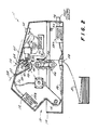
- FIGURES 1-4 An exemplary embodiment of the printer 10 is depicted at FIGURES 1-4. It generally includes an upper housing member 12 and a lower housing member 14 hingedly connected at 16 near the lower rear portion of the lower housing member 14. A rear portion of the housings include an angular configuration at 18 so as to accommodate a rotational opening motion to the open position shown in FIGURES 3 and 4. As will be observed, in the open position the rear relatively angled portion of the housings 12, 14 fit in abutting relationship. However, rather than to place the rotational connection near the parting line between the upper and lower housings (e.g.
- the preferred embodiment places the rotatable connection 16 at a lower rear location within the lower housing member 14 thus providing a rearward "over center” type of movement which provides an even wider open mouth in the paper loading access position depicted at FIGURES 3 and 4.
- the printer 10 includes the usual rotatable platen 20 which has a print station 22 located at its front side where printed indicia are imparted to a paper surface carried by the front side of the platen.
- Suitable guides 24, 26 may be conventionally provided for directing individual form sheets 28 input through an entrance slot 30 into engagement with the rear side of the platen 20 such that, upon rotation of the platen, the paper is directed around the past print station 22, under paper bail 32 and out paper exit slot 34.
- Printing may be performed at print station 22 by any conventional printing mechanism such as, for example, a conventional driven print ribbon 36 and a dot matrix print head 38 which is driven transversely along carriage 40 by conventional carriage drive mechanism 42.
- a continuous form tractor drive 44 (of conventional design) is mounted below the platen 20 and includes suitable paper guides 46, 48 so as to pull continuous form fan fold paper 50 or the like through a paper entrance slot 52 in the bottom of the lower housing member 14 and upwardly into engagement with the front side of platen 20 past the print station 22, under bail 32 and through paper exit slot 34.
- One or more conventional motors may be utilized for individually driving the print head along the carriage, the ribbon with respect to the print head, the platen 20 and the tractor drive 44.
- a single motor 54 has been schematically depicted for simplicity.
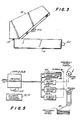
- the electronic printer controller may be housed where convenient. As depicted in FIGURE 2, the printer controller might comprise two printer circuit boards, one of which (board number 1) is mounted in the lower housing member 14 while the other (printer control board number 2) may be mounted in the upper housing member 12. Multiconductor cabling 56 may then be routed around the interior edges of the printer housings and in proximity with the rotational point 16 so as to interconnect the printer controller boards, the various drive motors 54, wire driving electromagnets and the print head 38, the carriage drive, etc.
- a transparent section 60 is also preferably provided so as to permit viewing of the print station area (or at least a view of the line that has just previously been printed) before the paper exits from slot 34.
- a sharp edge 62 may be provided in the transparent member 60 along the front of the exit slot 34 so as to provide a convenient tear off position for paper that has previously been printed (this is especially useful for the continuous form paper 50 as will be appreciated).
- the printer controller 58a, 58b may be connected to a convenience switch 64 that is actuated to a predetermined opened or closed position whenever the hinged housing members 12, 14 are opened such that the printer controller can be conditioned to automatically cease any printing operation whenever the housing members are rotated away from the closed position.
- a convenience switch 64 is also depicted schematically in FIGURE 2.
- the printer controller may also accept plug in font control modules 66 so as to permit convenient operator control of the printing font.
- the usual operator control switch panel 68 is also provided and interconnected via multiconductor cabling 56 to the appropriate printer control boards.
- a manual drive knob 70 may also be provided for the platen 20.
- the tractor drive mechanism 44 when the printer housing is rotated to its normal operative closed position, the tractor drive mechanism 44 is completely out of sight and out of the way. Nevertheless, it conveniently may be accessed for paper loading operations by merely rotating the upper housing upwardly and rearwardly to its opened position because the tractor drive 44 is also carried by the rotatable upper housing member and depends therefrom so as to provide ready access when the housing members are rotated to the open position.
Landscapes
- Handling Of Sheets (AREA)
Applications Claiming Priority (2)
| Application Number | Priority Date | Filing Date | Title |
|---|---|---|---|
| US79711985A | 1985-11-12 | 1985-11-12 | |
| US797119 | 1985-11-12 |
Publications (2)
| Publication Number | Publication Date |
|---|---|
| EP0226326A2 true EP0226326A2 (de) | 1987-06-24 |
| EP0226326A3 EP0226326A3 (de) | 1988-06-08 |
Family
ID=25169957
Family Applications (1)
| Application Number | Title | Priority Date | Filing Date |
|---|---|---|---|
| EP86308770A Withdrawn EP0226326A3 (de) | 1985-11-12 | 1986-11-11 | Drucker mit Traktormechanismus für Formularzufuhr |
Country Status (1)
| Country | Link |
|---|---|
| EP (1) | EP0226326A3 (de) |
Cited By (1)
| Publication number | Priority date | Publication date | Assignee | Title |
|---|---|---|---|---|
| WO1991005667A1 (de) * | 1989-10-13 | 1991-05-02 | Siemens Aktiengesellschaft | Druckeinrichtung |
Family Cites Families (3)
| Publication number | Priority date | Publication date | Assignee | Title |
|---|---|---|---|---|
| DE1937333U (de) * | 1966-03-08 | 1966-04-28 | Olympia Werke Ag | Einschaltsperre fuer kraftangetriebene schreib-, buchungs- oder aehnliche maschinen. |
| US3722655A (en) * | 1970-11-09 | 1973-03-27 | Ibm | Semi automatic form loading for printers |
| DE3208111C2 (de) * | 1982-03-06 | 1984-05-30 | Kienzle Apparate Gmbh, 7730 Villingen-Schwenningen | Druckeinrichtung in modularer Bauweise |
-
1986
- 1986-11-11 EP EP86308770A patent/EP0226326A3/de not_active Withdrawn
Cited By (2)
| Publication number | Priority date | Publication date | Assignee | Title |
|---|---|---|---|---|
| WO1991005667A1 (de) * | 1989-10-13 | 1991-05-02 | Siemens Aktiengesellschaft | Druckeinrichtung |
| US5238317A (en) * | 1989-10-13 | 1993-08-24 | Siemens Aktiengesellschaft | Printer providing a freely accessible printer frame |
Also Published As
| Publication number | Publication date |
|---|---|
| EP0226326A3 (de) | 1988-06-08 |
Similar Documents
| Publication | Publication Date | Title |
|---|---|---|
| US4806036A (en) | Printer mechanism carried by upper portion of hinged housing | |
| US5312196A (en) | Portable printer and sheet feeder | |
| US4828416A (en) | Vertical stand-alone printer | |
| US4761087A (en) | Printer with automatic printed paper advancement to tear-off position and subsequent retraction to new first print line | |
| US4830525A (en) | Typewriter with pivoting keyboard | |
| EP0811502B1 (de) | Hybrider Drucker und seine Bestandteile | |
| US5951181A (en) | Spaced-apart deflector structure for allowing manual insertion control of both sheet and rollfeed media | |
| EP0226326A2 (de) | Drucker mit Traktormechanismus für Formularzufuhr | |
| US5456540A (en) | Paper feed mechanism for interior drum type printer | |
| KR970003655B1 (ko) | 문서작성 인자장치 | |
| KR910019383A (ko) | 원고판독장치 | |
| US5035521A (en) | Envelope printing mechanism | |
| US12047539B2 (en) | Method and system for cable management within hinge mechanisms of rotating units in an image reading apparatus and printing apparatus | |
| JPS62220056A (ja) | 画像形成装置 | |
| JP2004322464A (ja) | 電子機器および記録装置 | |
| JP3289767B2 (ja) | プリンタ・スキャナ複合装置 | |
| JPH05257577A (ja) | 情報処理装置、プリンタあるいはこれらの情報処理装置とプリンタの組合せ装置 | |
| JPS6327283A (ja) | 印字装置 | |
| JP2685763B2 (ja) | 文書編集装置 | |
| JPH05181564A (ja) | 情報処理装置,文書処理装置、あるいは表示装置 | |
| JP2871999B2 (ja) | 用紙送り装置 | |
| JPS63270171A (ja) | プリンタにおける記録紙排出機構 | |
| JP2541414Y2 (ja) | 連続用紙カット機構 | |
| JPH04269567A (ja) | 文書編集装置 | |
| JPH04332671A (ja) | 自動給紙装置及び自動給紙装置とプリンタ、情報処理装置の組合せ装置 |
Legal Events
| Date | Code | Title | Description |
|---|---|---|---|
| PUAI | Public reference made under article 153(3) epc to a published international application that has entered the european phase |
Free format text: ORIGINAL CODE: 0009012 |
|
| AK | Designated contracting states |
Kind code of ref document: A2 Designated state(s): DE FR GB IT SE |
|
| RIN1 | Information on inventor provided before grant (corrected) |
Inventor name: WARD, DAVID O. Inventor name: HADTKE, FREDERICK B. Inventor name: ZAJAC, THEODORE S., JR. |
|
| PUAL | Search report despatched |
Free format text: ORIGINAL CODE: 0009013 |
|
| AK | Designated contracting states |
Kind code of ref document: A3 Designated state(s): DE FR GB IT SE |
|
| 17P | Request for examination filed |
Effective date: 19881027 |
|
| 17Q | First examination report despatched |
Effective date: 19900717 |
|
| STAA | Information on the status of an ep patent application or granted ep patent |
Free format text: STATUS: THE APPLICATION IS DEEMED TO BE WITHDRAWN |
|
| 18D | Application deemed to be withdrawn |
Effective date: 19910827 |
|
| RIN1 | Information on inventor provided before grant (corrected) |
Inventor name: ZAJAC, THEODORE S., JR. Inventor name: HADTKE, FREDERICK B. Inventor name: WARD, DAVID O. |