EP0226327A2 - Mechanismus zur Bogenhandhabung in einem Drucker - Google Patents
Mechanismus zur Bogenhandhabung in einem Drucker Download PDFInfo
- Publication number
- EP0226327A2 EP0226327A2 EP86308771A EP86308771A EP0226327A2 EP 0226327 A2 EP0226327 A2 EP 0226327A2 EP 86308771 A EP86308771 A EP 86308771A EP 86308771 A EP86308771 A EP 86308771A EP 0226327 A2 EP0226327 A2 EP 0226327A2
- Authority
- EP
- European Patent Office
- Prior art keywords
- paper
- tear
- bail
- printer
- control signal
- Prior art date
- Legal status (The legal status is an assumption and is not a legal conclusion. Google has not performed a legal analysis and makes no representation as to the accuracy of the status listed.)
- Granted
Links
Images


Classifications
-
- B—PERFORMING OPERATIONS; TRANSPORTING
- B41—PRINTING; LINING MACHINES; TYPEWRITERS; STAMPS
- B41J—TYPEWRITERS; SELECTIVE PRINTING MECHANISMS, i.e. MECHANISMS PRINTING OTHERWISE THAN FROM A FORME; CORRECTION OF TYPOGRAPHICAL ERRORS
- B41J11/00—Devices or arrangements of selective printing mechanisms, e.g. ink-jet printers or thermal printers, for supporting or handling copy material in sheet or web form
- B41J11/36—Blanking or long feeds; Feeding to a particular line, e.g. by rotation of platen or feed roller
- B41J11/42—Controlling printing material conveyance for accurate alignment of the printing material with the printhead; Print registering
- B41J11/44—Controlling printing material conveyance for accurate alignment of the printing material with the printhead; Print registering by devices, e.g. program tape or contact wheel, moved in correspondence with movement of paper-feeding devices, e.g. platen rotation
-
- B—PERFORMING OPERATIONS; TRANSPORTING
- B41—PRINTING; LINING MACHINES; TYPEWRITERS; STAMPS
- B41J—TYPEWRITERS; SELECTIVE PRINTING MECHANISMS, i.e. MECHANISMS PRINTING OTHERWISE THAN FROM A FORME; CORRECTION OF TYPOGRAPHICAL ERRORS
- B41J11/00—Devices or arrangements of selective printing mechanisms, e.g. ink-jet printers or thermal printers, for supporting or handling copy material in sheet or web form
- B41J11/66—Applications of cutting devices
- B41J11/70—Applications of cutting devices cutting perpendicular to the direction of paper feed
-
- B—PERFORMING OPERATIONS; TRANSPORTING
- B41—PRINTING; LINING MACHINES; TYPEWRITERS; STAMPS
- B41J—TYPEWRITERS; SELECTIVE PRINTING MECHANISMS, i.e. MECHANISMS PRINTING OTHERWISE THAN FROM A FORME; CORRECTION OF TYPOGRAPHICAL ERRORS
- B41J13/00—Devices or arrangements of selective printing mechanisms, e.g. ink-jet printers or thermal printers, specially adapted for supporting or handling copy material in short lengths, e.g. sheets
- B41J13/10—Sheet holders, retainers, movable guides, or stationary guides
- B41J13/20—Bails
Definitions
- This application relates generally to printers of the type commonly used as output devices in computer control data processing systems and the like.
- tear-off station so that a printed page or other portion of the paper may be neatly and conveniently torn off (or separated at a line of pre-formed perforations or the like).
- the tear-off station is coincident with the bail. In other printers the tear-off station may be located a substantial distance downstream from the bail member.
- the bail is manually operated and the tear-off function is manually achieved by manual manipulation of the platen, for example, so as to advance the paper as desired to the tear-off position and/or to retract the paper after tear-off to a desired new line of print position.
- the present invention includes a power driven bail member which, in conjunction with the paper drive mechanism, is programmed so as to automatically facilitate the paper tear-off function in an efficient and advantageous manner.
- the novel tear-off function is initiated by a first control signal which may, for example, be generated by an operator manipulated switch.
- the first control signal might be generated by the printer control circuits when an end-of-printed-document signal or the like is generated.
- the paper In response to this first control signal, the paper is advanced so that the last printed line is moved downstream of the tear-off station leaving the paper in a position where it can be immediately severed and used by an operator.
- a second control signal is generated (e.g. after some predetermined time lapse from the first control signal and/or in response to manual operator switch actuation or the like) so as to retract the new leading edge of the remaining paper into a desired new first print line position at the printing station.
- a power-driven bail is provided so that it may be released at least after such paper retraction until the paper is again advanced (e.g. during subsequent printing operations) to the point where paper is again disposed between the bail position and the platen whereupon the bail again may be actuated.
- a more complex bail actuation/de-actuation sequence may also be employed so as to even further facilitate the tear-off function.
- the paper bail is additionally released during paper advancement to the tear-off station and then re-applied to more firmly hold the paper in position during the tear-off operation.
- the bail bias may also be released again during retraction of the paper to the new desired print line position.
- the bail bias may immediately be applied once the paper is in the new print line position. Otherwise, the bail bias should remain deactivated until sufficient new printing has. occurred to again pass paper between the bail and the platen.
- FIGURES 1-2 An exemplary embodiment of the printer 10 is depicted at FIGURES 1-2. It generally includes an upper housing member 12 and a lower housing member 14 hingedly connected at 16 near the lower rear portion of the lower housing member 14. A rear portion of the housings include an angular configuration at 18 so as to accommodate a rotational opening motion to the open position. As will be observed, in the open position the rear relatively angled portions of the housings 12, 14 fit in abutting relationship. However, rather than to place the rotational connection near the parting line between the upper and lower housings (e.g. near the apex of the angled section 18), the preferred embodiment places the rotatable connection 16 at a lower rear location within the lower housing member 14 thus providing a rearward "over center" type of movement which provides an even wider open mouth in the paper loading access position.
- the printer 10 includes the usual rotatable platen 20 which has a print station 22 located at its front side where printed indicia are imparted to a paper surface carried by the front side of the platen.
- Suitable guides 24, 26 may be conventionally provided for directing individual form sheets 28 input through an entrance slot 30 into engagement with the rear side of the platen 20 such that, upon rotation of the platen, the paper is directed around and past print station 22, under paper bail 32 and out paper exit slot 34.
- Printing may be performed at print station 22 by any convention printing mechanism such as, for example, a conventional driven print ribbon 36 and a dot matrix print head 38 which is driven transversely along carriage 40 by conventional carriage drive mechanism 42.
- a continuous form tractor drive 44 (of conventional design) is mounted below the platen 20 and includes suitable paper guides 46, 48 so as to pull continuous form fan fold paper 50 or the like through a paper entrance slot 52 in the bottom of the lower housing member 14 and upwardly into engagement with the front side of platen 20 past the print station 22, under bail 32 and through paper exit slot 34.
- One or more conventional motors may be utilized for individually driving the print head along the carriage, the ribbon with respect to the print head, the platen 20 and the tractor drive 544.
- a single motor 54 has been schematically depicted for simplicity.
- the electronic printer controller may be housed where convenient. As depicted in FIGURE 1, the printer controller might comprise two printer circuit boards, one of which (board number 1) is mounted in the lower housing member 14 while the other ( printer control board number 2) may be mounted in the upper housing member 12. Multiconductor cabling 56 may then be routed around the interior edges of the printer housings and in proximity with the rotational point 16 so as to interconnect the printer controller boards, the various drive motors 54, wire driving electromagnets and the print head 38, the carriage drive, etc.
- a transparent section 60 is also preferably provided so as to permit viewing of the print station area (or at least a view of the line that has previously been printed) before the paper exits from slot 34.
- a sharp edge 62 may be provided in the transparent member 60 along the front of the exit slot 34 so as to provide a convenient tear off position for paper that has previously been printed (this is especially useful for the continuous form paper 50 as will be appreciated).
- the printer controller 58a, 58b may be connected to a convenience switch 64 that is actuated to a predetermined opened or closed position whenever the hinged housing members 12, 14 are opened such that the printer controller can be conditioned to automatically cease any printing operation whenever the housing members are rotated away from the closed position.
- a convenience switch 64 is also depicted schematically in FIGURE 1.
- the printer controller may also accept plug in font control modules 66 so as to permit convenient operator control of the printing font.
- the usual operator control switch panel 68 is also provided and interconnected via multiconductor cabling 56 to the appropriate printer control boards.
- a manual drive knob 70 may also be provided for the platen 20.
- the exemplary embodiment includes an electro-mechanical bail drive mechanism 100 (e.g. a motor, electromagnetic actuator, etc.) which is capable of physically moving the bail 32 into a pressure biased position against the platen 20 or away there from so as permit paper to freely pass between the bail and the platen.
- the bail is energized into engagement with the platen so as to engage in intermediate paper whenever there is paper present at that location and either (a) a printing operation is underway or (b) the paper is in position for operator tear-off.
- the bail may be left in engagement with the paper at all times except in the event that the new leading edge of the paper (i.e.
- bail drive 100 is deactivated so as to retract the bail and permit free paper movements thereunder during subsequent printing/paper advancement times until paper once again is present between bail 32 and the platen 20 whereupon the bail drive member 100 may again be actuated.
- the paper bail 32 and the paper tear-off station 62 there may be a significant distance between the paper bail 32 and the paper tear-off station 62 (e.g. it might be as much as six lines or so of print positions).
- the distance between the bail 32 and the tear-off station 62 will, of course, vary from one embodiment to the next in accordance with the printer design criteria.
- the printer controller 58A, 58B which drives all of the printer mechanisms including the bail drive 100 is in the exemplary embodiment an microprocessor-based device.
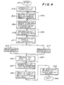
- the microprocessor controller may be of conventional design except for the tear-off function which may be embodied in a suitable computer program of the type depicted in the flow chart of FIGURE 4.
- this tear-off function program may be embodied as a separate sub-routine or embodied directly within other printer controller program routines.
- Entry to the tear-off function 300 may actually occur as a result of an interrupt signal or the like which may occur at step 302 as a result of depression of an operator control switch (e.g. one of switched 68 on the control panel).
- an end of document control signal or the like may suffice for creation of a first control signal which causes entry to the tear-off function routine.
- the paper bail is released at step 304 and the paper is thereafter advanced at step 306 to a desired tear-off position via the conventional paper drive mechanism.
- the paper bail bias is re-applied at step 308 and time is provided for an operator manual tear-off function (or automatic tear-off, cutting, etc.) at step 310 either by a predetermined time delay 312 or until depression of a second switch at step 314 (or otherwise generating a second control signal by program or other means) before progressing further in a tear-off function flow Chart of FIGURE 4.
- the bail bias is again released at step 316 and the new leading edge of the paper is retracted at step 318 to a desired new print position.
- step 320 if six lines of normal printing operations are to occur at step 320 before the bail bias is re-applied at step 322, then 322 may actually be embodied within the normal print routine in conjunction with suitable data flags or the like indicating that a new printing operation has been initiated just subsequent to a tear-off function so that step 322 is to be performed after six lines worth of paper advancement have occurred.
Landscapes
- Handling Of Sheets (AREA)
Applications Claiming Priority (2)
| Application Number | Priority Date | Filing Date | Title |
|---|---|---|---|
| US797121 | 1985-11-12 | ||
| US06/797,121 US4761087A (en) | 1985-11-12 | 1985-11-12 | Printer with automatic printed paper advancement to tear-off position and subsequent retraction to new first print line |
Publications (3)
| Publication Number | Publication Date |
|---|---|
| EP0226327A2 true EP0226327A2 (de) | 1987-06-24 |
| EP0226327A3 EP0226327A3 (en) | 1988-06-08 |
| EP0226327B1 EP0226327B1 (de) | 1991-07-24 |
Family
ID=25169965
Family Applications (1)
| Application Number | Title | Priority Date | Filing Date |
|---|---|---|---|
| EP86308771A Expired EP0226327B1 (de) | 1985-11-12 | 1986-11-11 | Mechanismus zur Bogenhandhabung in einem Drucker |
Country Status (3)
| Country | Link |
|---|---|
| US (1) | US4761087A (de) |
| EP (1) | EP0226327B1 (de) |
| DE (1) | DE3680489D1 (de) |
Cited By (6)
| Publication number | Priority date | Publication date | Assignee | Title |
|---|---|---|---|---|
| US4925325A (en) * | 1987-04-23 | 1990-05-15 | Brother Kogyo Kabushiki Kaisha | Recording paper transporting device in a recording apparatus |
| US4957381A (en) * | 1987-10-30 | 1990-09-18 | Brother Kogyo Kabushiki Kaisha | Paper feeding and cutting control device in a recording apparatus |
| US4968165A (en) * | 1987-08-24 | 1990-11-06 | Brother Kogyo Kabushiki Kaisha | Sheet feed control device and method in a printer with a tear bar |
| DE4023499A1 (de) * | 1989-08-24 | 1991-02-28 | Sato Kk | Kontinuierlicher papierselbstlademechanismus fuer thermodrucker |
| US6712253B2 (en) | 2001-06-04 | 2004-03-30 | American Games, Inc. | Apparatus and method for dispensing tickets |
| CN109455563A (zh) * | 2018-12-27 | 2019-03-12 | 常州汉威信科技股份有限公司 | 撕纸张装置及方法 |
Families Citing this family (10)
| Publication number | Priority date | Publication date | Assignee | Title |
|---|---|---|---|---|
| US5069565A (en) * | 1986-06-24 | 1991-12-03 | Jeffrey Ayd | Computer printer for printing labels and tags having vertically orientated tractor feed |
| US5199806A (en) * | 1987-06-30 | 1993-04-06 | Seiko Epson Corporation | Apparatus for feeding individual sheets of paper as well as continuous fan fold paper utilizing a platen |
| US5221150A (en) * | 1987-06-30 | 1993-06-22 | Seiko Epson Corporation | Paper feeding apparatus for printers having a bail roller means |
| EP0311980A3 (de) * | 1987-10-14 | 1990-01-03 | Tokyo Electric Co., Ltd. | Thermodrucker |
| JPH01103472A (ja) * | 1987-10-16 | 1989-04-20 | Brother Ind Ltd | 印字用シート頭出し機能付印字装置 |
| DE68903233T2 (de) * | 1988-03-14 | 1993-04-08 | Seiko Epson Corp | Verfahren und vorrichtung zur papierzufuhr in dem drucker. |
| US6981254B2 (en) * | 2001-02-01 | 2005-12-27 | Hewlett-Packard Development Company, L.P. | Delay timer for printing from the driver |
| US6827515B2 (en) * | 2003-03-04 | 2004-12-07 | Transact Technologies Incorporated | Stacker for a printer |
| US7066670B2 (en) | 2004-02-10 | 2006-06-27 | Tallygenicom Lp | Printing method and apparatus |
| US8177224B2 (en) * | 2009-12-15 | 2012-05-15 | Transact Technologies Incorporated | Methods and apparatus for shingle stacking of tickets in a ticket printer |
Family Cites Families (17)
| Publication number | Priority date | Publication date | Assignee | Title |
|---|---|---|---|---|
| US3075626A (en) * | 1960-02-04 | 1963-01-29 | Victor Adding Machine Co | Record tape feed mechanism for business machines |
| CH412414A (de) * | 1961-03-02 | 1966-04-30 | Walther Bueromasch Gmbh | Zeilenschalteinrichtung an Zehntasten-Addier- und Vierspezies-Rechenmaschinen |
| BE756419A (fr) * | 1969-11-19 | 1971-03-01 | Ibm | Dispositif d'alimentation verticale du support d'impression pour machine imprimante telle que machine a ecrire |
| US3844395A (en) * | 1973-09-12 | 1974-10-29 | Extel Corp | Text display control for data printer |
| DE2633498A1 (de) * | 1976-07-26 | 1978-02-02 | Siemens Ag | Anordnung zum einstellen der querspalten eines formulars fuer drucker, insbesondere fernschreibmaschinen |
| US4234261A (en) * | 1977-04-04 | 1980-11-18 | Mannesmann Aktiengesellschaft | Printer |
| JPS5784885A (en) * | 1980-11-14 | 1982-05-27 | Usac Electronics Ind Co Ltd | Leading-end protruding method for slip form medium in printer |
| JPS57107873A (en) * | 1980-12-25 | 1982-07-05 | Ricoh Co Ltd | Printer |
| DE3112461A1 (de) * | 1981-03-28 | 1982-10-14 | Kienzle Apparate Gmbh, 7730 Villingen-Schwenningen | Abreissvorrichtung fuer randgelochte formularbahnen |
| JPS57167283A (en) * | 1981-04-09 | 1982-10-15 | Fujitsu Ltd | Printer |
| US4452543A (en) * | 1982-01-15 | 1984-06-05 | Florida Data Corporation | High speed printer with multiple paper paths |
| IT1155264B (it) * | 1982-02-25 | 1987-01-28 | Olivetti & Co Spa | Introduttore di documenti |
| DE3306083A1 (de) * | 1982-02-22 | 1983-09-01 | Ricoh Co., Ltd., Tokyo | Papierzufuhr-steuersystem |
| US4422787A (en) * | 1982-05-10 | 1983-12-27 | Guthrie George L | Tear bar for a printer |
| JPS59118481A (ja) * | 1982-12-25 | 1984-07-09 | Fujitsu Ltd | 媒体送り機構 |
| JPS59176064A (ja) * | 1983-03-25 | 1984-10-05 | Ricoh Co Ltd | カラ−プリンタの記録制御方式 |
| JPS60155478A (ja) * | 1984-01-25 | 1985-08-15 | Sharp Corp | プリンタにおける用紙送り装置 |
-
1985
- 1985-11-12 US US06/797,121 patent/US4761087A/en not_active Expired - Lifetime
-
1986
- 1986-11-11 EP EP86308771A patent/EP0226327B1/de not_active Expired
- 1986-11-11 DE DE8686308771T patent/DE3680489D1/de not_active Expired - Fee Related
Cited By (9)
| Publication number | Priority date | Publication date | Assignee | Title |
|---|---|---|---|---|
| US4925325A (en) * | 1987-04-23 | 1990-05-15 | Brother Kogyo Kabushiki Kaisha | Recording paper transporting device in a recording apparatus |
| US5071274A (en) * | 1987-04-23 | 1991-12-10 | Brother Kogyo Kabushiki Kaisha | Recording paper transporting device for aligning top print line margin and cutting line |
| US4968165A (en) * | 1987-08-24 | 1990-11-06 | Brother Kogyo Kabushiki Kaisha | Sheet feed control device and method in a printer with a tear bar |
| US4957381A (en) * | 1987-10-30 | 1990-09-18 | Brother Kogyo Kabushiki Kaisha | Paper feeding and cutting control device in a recording apparatus |
| EP0314517B1 (de) * | 1987-10-30 | 1993-09-01 | Brother Kogyo Kabushiki Kaisha | Einrichtung zum Steuern der Papierzufuhr in einem Registrierapparat |
| DE4023499A1 (de) * | 1989-08-24 | 1991-02-28 | Sato Kk | Kontinuierlicher papierselbstlademechanismus fuer thermodrucker |
| US6712253B2 (en) | 2001-06-04 | 2004-03-30 | American Games, Inc. | Apparatus and method for dispensing tickets |
| CN109455563A (zh) * | 2018-12-27 | 2019-03-12 | 常州汉威信科技股份有限公司 | 撕纸张装置及方法 |
| CN109455563B (zh) * | 2018-12-27 | 2024-02-23 | 常州汉威信科技股份有限公司 | 撕纸张装置及方法 |
Also Published As
| Publication number | Publication date |
|---|---|
| US4761087A (en) | 1988-08-02 |
| EP0226327A3 (en) | 1988-06-08 |
| EP0226327B1 (de) | 1991-07-24 |
| DE3680489D1 (de) | 1991-08-29 |
Similar Documents
| Publication | Publication Date | Title |
|---|---|---|
| EP0226327B1 (de) | Mechanismus zur Bogenhandhabung in einem Drucker | |
| US4806036A (en) | Printer mechanism carried by upper portion of hinged housing | |
| JP3012431B2 (ja) | テープ切断装置及び印字装置 | |
| EP0137892B1 (de) | Handetikettiergerät | |
| US5159350A (en) | Tape printing apparatus | |
| JP2943314B2 (ja) | プリンタ | |
| EP0416507A2 (de) | Etikettenausgabevorrichtung | |
| EP0404538A1 (de) | Papiertransportapparat | |
| JPS60137675A (ja) | プリンタ装置 | |
| JP3332244B2 (ja) | テープ印字装置 | |
| JPS6274673A (ja) | 印字用紙カツト機構 | |
| JPS6244471A (ja) | 印字装置の用紙搬送機構 | |
| JP2844821B2 (ja) | 記録担体の切り離し装置 | |
| JPS59158281A (ja) | 印字制御装置 | |
| JPH0582829B2 (de) | ||
| JPH03224764A (ja) | 連続記録紙の記録装置 | |
| JPS5828289Y2 (ja) | 印字兼表示装置 | |
| JPS6345073A (ja) | 卓上形ラベルプリンタ | |
| JP2526697B2 (ja) | 給紙機構を備えた印字装置 | |
| JP2685763B2 (ja) | 文書編集装置 | |
| JPS643672B2 (de) | ||
| JP3001706B2 (ja) | 記録装置 | |
| JPS58145480A (ja) | プリンタの駆動制御装置 | |
| JP2511763Y2 (ja) | 発券機 | |
| JP2582417B2 (ja) | プリンタ |
Legal Events
| Date | Code | Title | Description |
|---|---|---|---|
| PUAI | Public reference made under article 153(3) epc to a published international application that has entered the european phase |
Free format text: ORIGINAL CODE: 0009012 |
|
| AK | Designated contracting states |
Kind code of ref document: A2 Designated state(s): DE FR GB IT SE |
|
| RIN1 | Information on inventor provided before grant (corrected) |
Inventor name: WARD, DAVID O. Inventor name: ZAJAC, THEODORE S, JR. |
|
| PUAL | Search report despatched |
Free format text: ORIGINAL CODE: 0009013 |
|
| AK | Designated contracting states |
Kind code of ref document: A3 Designated state(s): DE FR GB IT SE |
|
| 17P | Request for examination filed |
Effective date: 19881031 |
|
| 17Q | First examination report despatched |
Effective date: 19900717 |
|
| GRAA | (expected) grant |
Free format text: ORIGINAL CODE: 0009210 |
|
| AK | Designated contracting states |
Kind code of ref document: B1 Designated state(s): DE FR GB IT SE |
|
| PG25 | Lapsed in a contracting state [announced via postgrant information from national office to epo] |
Ref country code: IT Free format text: LAPSE BECAUSE OF FAILURE TO SUBMIT A TRANSLATION OF THE DESCRIPTION OR TO PAY THE FEE WITHIN THE PRESCRIBED TIME-LIMIT;WARNING: LAPSES OF ITALIAN PATENTS WITH EFFECTIVE DATE BEFORE 2007 MAY HAVE OCCURRED AT ANY TIME BEFORE 2007. THE CORRECT EFFECTIVE DATE MAY BE DIFFERENT FROM THE ONE RECORDED. Effective date: 19910724 Ref country code: SE Effective date: 19910724 |
|
| REF | Corresponds to: |
Ref document number: 3680489 Country of ref document: DE Date of ref document: 19910829 |
|
| EN | Fr: translation not filed | ||
| PG25 | Lapsed in a contracting state [announced via postgrant information from national office to epo] |
Ref country code: FR Effective date: 19911213 |
|
| PLBE | No opposition filed within time limit |
Free format text: ORIGINAL CODE: 0009261 |
|
| STAA | Information on the status of an ep patent application or granted ep patent |
Free format text: STATUS: NO OPPOSITION FILED WITHIN TIME LIMIT |
|
| 26N | No opposition filed | ||
| REG | Reference to a national code |
Ref country code: FR Ref legal event code: ST |
|
| REG | Reference to a national code |
Ref country code: GB Ref legal event code: 732E |
|
| PGFP | Annual fee paid to national office [announced via postgrant information from national office to epo] |
Ref country code: GB Payment date: 20011114 Year of fee payment: 16 |
|
| PGFP | Annual fee paid to national office [announced via postgrant information from national office to epo] |
Ref country code: DE Payment date: 20011126 Year of fee payment: 16 |
|
| REG | Reference to a national code |
Ref country code: GB Ref legal event code: IF02 |
|
| PG25 | Lapsed in a contracting state [announced via postgrant information from national office to epo] |
Ref country code: GB Free format text: LAPSE BECAUSE OF NON-PAYMENT OF DUE FEES Effective date: 20021111 |
|
| PG25 | Lapsed in a contracting state [announced via postgrant information from national office to epo] |
Ref country code: DE Free format text: LAPSE BECAUSE OF NON-PAYMENT OF DUE FEES Effective date: 20030603 |
|
| GBPC | Gb: european patent ceased through non-payment of renewal fee |