EP0226374A2 - Luminomètre - Google Patents
Luminomètre Download PDFInfo
- Publication number
- EP0226374A2 EP0226374A2 EP86309341A EP86309341A EP0226374A2 EP 0226374 A2 EP0226374 A2 EP 0226374A2 EP 86309341 A EP86309341 A EP 86309341A EP 86309341 A EP86309341 A EP 86309341A EP 0226374 A2 EP0226374 A2 EP 0226374A2
- Authority
- EP
- European Patent Office
- Prior art keywords
- cuvette
- luminometer
- carrier
- cuvettes
- construction
- Prior art date
- Legal status (The legal status is an assumption and is not a legal conclusion. Google has not performed a legal analysis and makes no representation as to the accuracy of the status listed.)
- Withdrawn
Links
- 238000010276 construction Methods 0.000 title claims abstract description 26
- 238000012360 testing method Methods 0.000 claims abstract description 39
- 238000011068 loading method Methods 0.000 claims abstract description 12
- 230000003287 optical effect Effects 0.000 claims abstract description 7
- 238000002360 preparation method Methods 0.000 claims description 6
- 238000012545 processing Methods 0.000 claims description 6
- 238000004458 analytical method Methods 0.000 claims description 2
- 238000003780 insertion Methods 0.000 claims description 2
- 230000037431 insertion Effects 0.000 claims description 2
- 238000012544 monitoring process Methods 0.000 claims description 2
- 238000010998 test method Methods 0.000 claims 3
- 238000002203 pretreatment Methods 0.000 claims 1
- 239000000523 sample Substances 0.000 description 25
- 239000000126 substance Substances 0.000 description 7
- ZKHQWZAMYRWXGA-KQYNXXCUSA-N Adenosine triphosphate Chemical compound C1=NC=2C(N)=NC=NC=2N1[C@@H]1O[C@H](COP(O)(=O)OP(O)(=O)OP(O)(O)=O)[C@@H](O)[C@H]1O ZKHQWZAMYRWXGA-KQYNXXCUSA-N 0.000 description 6
- ZKHQWZAMYRWXGA-UHFFFAOYSA-N Adenosine triphosphate Natural products C1=NC=2C(N)=NC=NC=2N1C1OC(COP(O)(=O)OP(O)(=O)OP(O)(O)=O)C(O)C1O ZKHQWZAMYRWXGA-UHFFFAOYSA-N 0.000 description 6
- 229960001456 adenosine triphosphate Drugs 0.000 description 6
- 239000003153 chemical reaction reagent Substances 0.000 description 5
- 238000005259 measurement Methods 0.000 description 5
- 238000000034 method Methods 0.000 description 5
- 239000007788 liquid Substances 0.000 description 4
- 238000000429 assembly Methods 0.000 description 3
- 239000006194 liquid suspension Substances 0.000 description 3
- 238000002156 mixing Methods 0.000 description 3
- 230000002411 adverse Effects 0.000 description 2
- 230000000712 assembly Effects 0.000 description 2
- 238000001816 cooling Methods 0.000 description 2
- 238000000605 extraction Methods 0.000 description 2
- 235000013305 food Nutrition 0.000 description 2
- 238000011160 research Methods 0.000 description 2
- 239000004793 Polystyrene Substances 0.000 description 1
- 238000013019 agitation Methods 0.000 description 1
- 230000005540 biological transmission Effects 0.000 description 1
- 238000006243 chemical reaction Methods 0.000 description 1
- 238000004891 communication Methods 0.000 description 1
- 238000004590 computer program Methods 0.000 description 1
- 238000010924 continuous production Methods 0.000 description 1
- 238000007405 data analysis Methods 0.000 description 1
- 238000013480 data collection Methods 0.000 description 1
- 238000001514 detection method Methods 0.000 description 1
- 238000011161 development Methods 0.000 description 1
- 230000000694 effects Effects 0.000 description 1
- 238000010438 heat treatment Methods 0.000 description 1
- 238000011534 incubation Methods 0.000 description 1
- 230000000977 initiatory effect Effects 0.000 description 1
- 238000002347 injection Methods 0.000 description 1
- 239000007924 injection Substances 0.000 description 1
- 210000003141 lower extremity Anatomy 0.000 description 1
- 239000008267 milk Substances 0.000 description 1
- 210000004080 milk Anatomy 0.000 description 1
- 235000013336 milk Nutrition 0.000 description 1
- 238000000465 moulding Methods 0.000 description 1
- 229920002223 polystyrene Polymers 0.000 description 1
- 238000012216 screening Methods 0.000 description 1
- 239000010802 sludge Substances 0.000 description 1
- 239000000243 solution Substances 0.000 description 1
- 238000012421 spiking Methods 0.000 description 1
- XLYOFNOQVPJJNP-UHFFFAOYSA-N water Substances O XLYOFNOQVPJJNP-UHFFFAOYSA-N 0.000 description 1
Images


Classifications
-
- G—PHYSICS
- G01—MEASURING; TESTING
- G01N—INVESTIGATING OR ANALYSING MATERIALS BY DETERMINING THEIR CHEMICAL OR PHYSICAL PROPERTIES
- G01N21/00—Investigating or analysing materials by the use of optical means, i.e. using sub-millimetre waves, infrared, visible or ultraviolet light
- G01N21/75—Systems in which material is subjected to a chemical reaction, the progress or the result of the reaction being investigated
- G01N21/76—Chemiluminescence; Bioluminescence
Definitions
- a luminometer is a device for measuring light photons, particularly at low light levels, produced by bio-luminescent or chemi-luminescent effects.
- the luminometer construction with which the invention is concerned is designed to detect and measure light emission produced as a result of chemical or other reactions, the measurement being translated into a signal which may take one of many forms, according to particular tests being undertaken.
- Typical circumstances in which the luminometer may be used include testing of samples of liquids to determine various factors and the device may be used in medical applications, in the food and drink, pharmaceutical, water treatment, or other industries. It may also be used for research in various fields.
- the luminometer has means for presenting a sample, usually as a liquid or a liquid suspension, to a photo-multiplier device by means of which the actual measurement is carried out.
- This preparation may include extraction of ATP (adenosine-5'-triphosphate) molecules, adding suitable reagents or other processes to produce light emissions of sufficient intensity to be detectable and measurable by the photo-multiplier device. It is also possible to carry out certain functions while the sample is presented to the photo-multiplier device.
- ATP adenosine-5'-triphosphate
- a number of methods have been devised for presenting samples to the photo-multiplier, which is extremely sensitive and must be screened against extraneous influences.
- the requirement for examination of a large number of samples in succession has resulted in the development of various systems for bringing the samples to the apparatus in a conveyor arrangement, each sample being presented in turn for examination and then returned to the conveyor arrangement.
- the samples are, in such a system, contained in individual transparent cuvettes, which are placed, in turn, into a chamber which is open, or in communication, at least at an appropriate time, to the photo-multiplier.
- a luminometer construction including means for supplying samples, contained in respective individual cuvettes, in succession to be examined, to a carrier, whereby they are presented in turn to a photo-multiplier device, the carrier comprising a rotatable structure having a portion defining an examination chamber, and a cuvette gripper arranged to hold a cuvette in a position such that a sample containing portion thereof is within the examination chamber, and the carrier being rotatable between a loading position in which the cuvettes can be inserted into the gripper and a test position in which the chamber is positioned adjacent to the photo-multiplier device.
- the carrier is mounted for rotation about an axis and the cuvette gripper is arranged for insertion of cuvettes in a direction substantially parallel with that axis, the examination chamber being formed in the side of the carrier with an external edge in a plane inclined to the said axis and the photo-mulitplier device being positioned with its own optical axis perpendicular to the said plane of the edge of the examination chamber.
- the examination chamber is in the form of a concave recess or cavity in the side of the carrier, having an edge conforming generally to the shape of the adjacent end of the operative part of the photo-multiplier device.
- the chamber has a single hole through which a cuvette, in use, can extend whereby in the test position, the centre line of the cuvette intersects the optical axis of the photo-mulitplier device at a position close to the said plane of the edge of the examination chamber.
- the cuvette base containing a sample is, in use, positioned close to the photo-multiplier device and on its axis, so that the collection of light photons is optimised.
- the cuvette gripper is preferably situated in a position enabling cuvettes to be introduced through the examination chamber and into the single hole referred to, the cuvettes being withdrawn also in the opposite direction, the examination chamber being shaped and positioned to allow for the introduction and withdrawal of cuvettes without necessity for other holes or cut-outs for the passage of the cuvettes.
- the angle of the plane of the edge of the examination chamber, relatively to the axis of rotation of the carrier is preferably 35 0 , in order to enable the cuvettes to be conveniently introduced and withdrawn.
- the cuvettes may be brought to and carried away from the luminometer by a conveyor arrangement. This may include a number of individual holders which may be brought into the cuvette loading position in turn, a cuvette being extracted from the holder and transferred into the cuvette gripper, the carrier then being rotated to bring the cuvette into the test position and after testing, the carrier being again rotated to the loading position at which the cuvette is returned to its holder.
- the holders may be interconnected to make up a bandolier which is driven in steps to present successive cuvettes to the instrument for test, in turn.
- a drive mechanism is conveniently provided to drive the cuvette holders in sequence with rotational movements of the carrier and with means for transferring cuvettes from their holders into the cuvette gripper and returning them thereto.
- a controller may be provided which is capable of controlling functions of the luminometer or of equipment associated with the luminometer, including identification of a sample provided, setting up or adjusting the luminometer in preparation for a particular test, controlling sample preparation operations, actuation of sample handling equipment, energisation of the photo-multiplier device, and processing of data provided, in use, from the photo-multiplier device to provide an output in a required form.
- the controller preferably includes software which is dedicated to a particular test to be carried out and conveniently carries out all necessary functions to produce a test result.
- the controller includes a means for monitoring the photo-multiplier device.
- accuracy of measurement can be maintained at a high level.
- Functions carried out by the controller may be performed by apparatus within the luminometer construction or externally thereof.
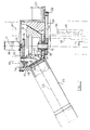
- Figure 1 shows a luminometer construction intended for the test of liquids or liquid suspensions, and wherein the substances are contained within individual transparent cuvettes which are brought to the instrument in turn.
- the substance may be subjected to processes which may be bio-luminescent or chemi-luminescent, creating emission of light photons which are detected by a photo-multiplier device in the instrument.
- the drawing shows a rotatable carrier 10 in the form of a bowl mounted for rotation about a vertical axis 11.
- the bowl is mounted on a short shaft 12 which is carried on a fixed structure 13.
- the fixed structure is shown as an outer bowl with a lid 14 carrying a shaft 15, the centre of which is also on the axis 11.
- the shaft 15 has a gear 16 which is below the lid 14 and therefore within the space also occupied by the bowl 10.
- the gear 16 meshes with a gear 17 journalled by means of a hollow shaft 18 fixed in the upper part of the bowl 10. within the hollow shaft is a cuvette gripper 19 for gripping a cuvette 20, to which reference will be made later.
- the bowl 10 has a generally frustoconical shape with the narrower end downwards and connected to the short shaft 12.
- the circular side of the bowl is therefore inclined downwardly and the angle of the inclination, in this example, is 35° with respect to the vertical axis 11.
- an examination chamber 21 which is also shown in Figure la. This has concave form, the profile being generally ellipsoidal.
- the internal surface is reflective as indicated at 22.
- the edge of the chamber 21 is therefore generally circular and is substantially in a plane which is inclined at 35° to the vertical axis 11.
- the cuvette 20, as shown in Figure 1 can extend into the examination chamber 21.
- the cuvette as shown in Figure 2 is a small transparent test tube having one end closed to form a generally hemi-spherical end portion 23.
- Cuvettes may be made from polystyrene.
- moulded ribs 24 which aid agitation of the contents. These could be omitted, if not required.
- the cuvette is positioned so that the centre of the hemi-spherical end 23 coincides with the cusp of the ellipse formed by the examination chamber 21. This is spaced from the plane defined by the edge of the chamber by a distance approximating to the external radius of the hemi-spherical end of the cuvette.
- a photo-multiplier tube device 25 Positioned adjacent to the chamber 21 when it is in the test position as shown in Figure 1 is a photo-multiplier tube device 25. This is of highly sensitive type and requires to be screened from extraneous light or other discharge sources. It is therefore positioned within the outer structure 13 in a manner sealed from external light emissions.
- the optical axis 26 of the photo-multiplier tube is perpendicular to the plane of the edge of the chamber and is therefore coincident with the central axis of the ellipse formed by the chamber 21. It can be seen from Figure 1 that when a cuvette 20 is in the test position as shown, the hemi-spherical end of the cuvette is very close to the operative end of the photo-multiplier tube and the axes of the cuvette and of the photo-multiplier tube optical system intersect.
- the bowl 10 is rotatable within the fixed structure 13 and to carry out such rotation an electric motor 27 is provided.
- This carries a pulley 28, driving belt 29, engaging over a further pulley 30 which is carried on the short vertical shaft 12 for the bowl 10.
- the bowl 10 is arranged to be rotated through 180° between a cuvette loading position and the test position shown in Figure 1.
- Figure 6 shows a cuvette 20 ready to be loaded into the bowl.
- the cuvettes are lifted vertically to pass through a hole 31 in the fixed structure 13. It is possible to load a cuvette only when the chamber 21 is in the load position, that is, in register with the hole 31.
- the angle of the edge of the chamber 21 is such that the cuvette will pass the lower extremity of that edge with a small clearance.
- the cuvette is lifted so that its upper end registers with a hole 32 in the top of the chamber 21 and this is aligned with the gripper 19.
- a lifting mechanism shown particularly in Figure 6.
- This comprises a vertical rotatable shaft 33, having its ends mounted in bearings in a fixed frame forming part of the structure 13.
- the shaft 33 is screw threaded and a ball nut assembly 34 is engaged on the shaft so that when the shaft is rotated, the ball nut assembly 34 will lift.
- An arm on the ball nut assembly carries a vertical push rod 35 to the top of which is secured a pusher pad 36 which can engage underneath a cuvette 20 to lift it vertically into the loaded position.
- a pulley 37 is secured to the lower end of the shaft. This is driven through a belt drive indicated in outline in Figure 1 at 38.
- the cuvettes are brought to the luminometer by a conveyor arrangement which comprises a bandolier made up from a number of interconnected cuvette holders, one of which is shown in Figure 3.
- the holder 39 is a small tubular moulding with four integral lugs.
- the lug 40 is a hollow eye, whereas the lug 41 is hook-shaped.
- the lug 42 has a small circular spigot and the lug 43 has a flattened spigot. It is possible to join adjacent cuvette holders together by engaging the lugs.
- the lugs 40, 42 are engaged by dropping the pin into the socket, and the pin on the lug 43 can be engaged laterally in the hook-shaped lug 41.
- the individual cuvettes are engaged in their holders by friction, and in the side of the cuvette holder 39 there is a resilient detent 44 which is pressed aside when a cuvette is entered into the holder and which serves to provide the frictional resistance against release of the cuvette out of the holder.
- a resilient detent 44 which is pressed aside when a cuvette is entered into the holder and which serves to provide the frictional resistance against release of the cuvette out of the holder.
- the pusher assembly engages and pushes up on the bottom of a cuvette, it will readily slide out of the holder.
- the cuvette holders 39 are driven, in turn, by means of a mechanism shown in Figures 4, 5, and 6.
- Two vertically mounted star wheels 45, 46, are carried on respective vertical shafts 47, 48.
- a bevel gear 49, 50 engaging with respective bevel gears 51, 52, on a common shaft 53.
- the shaft 53 carries a pulley 54 engaged by a belt 55, also passing over a pulley 56 on a motor shaft 57 of a motor 58.
- the star wheels 45, 46 are relatively close together and have lobes which can engage between the cuvette holders 39 in the bandolier. This arrangement is shown in outline in Figure 4.
- the cuvettes are brought in their holders in turn to the loading position which is in the centre between the two star wheels 45, 46, and at this position the pusher assembly lifts the cuvettes as already described.
- a liquid handling system is positioned in the top of the luminometer. This may be used to inject measured quantities of reagents and/or samples of other substances directly into the cuvettes, as may be required, while the cuvettes are presented to the photo-multiplier device or at other positions.
- the system is generally identified in the drawings at 59.
- the shaft 15 in the centre of the top of the lid 14 may carry an agitator device 60 which drives through the gears 16, 17, which carry the cuvette gripper already described. This serves to agitate the sample to ensure adequate mixing and thus uniformity of the emission of light photons.
- a device 61 To extract the cuvettes from the bowl when tests have been carried out, a device 61 is provided. This includes a pusher arranged to drive cuvettes downwardly into engagement with their respective holders.
- the construction includes appropriate electrical circuits whereby the sample handling apparatus is actuated in the required sequence.
- the three main sub-assemblies comprising the bowl and its housing and the associated parts, the cuvette lift mechanism, and the bandolier system, are all mounted on a common base and are so connected that movement between assemblies is prevented, in order to ensure accuracy of operation and thus reliability of result.
- a suitable cabinet may enclose all the assemblies.
- Figure 7 shows in diagrammatic form, a system layout in which the main sample processing unit which comprises the luminometer construction and its cuvette supply system, is connected to a controller, which in this case includes a micro-computer 61 to which are connected a disc drive 62, a display unit (VDU) 63, and a printer 64.
- a controller which in this case includes a micro-computer 61 to which are connected a disc drive 62, a display unit (VDU) 63, and a printer 64.
- Figure 8 shows an alternative arrangement in which the main sample processing unit 65 is provided with an onboard micro-computer 66, which is controlled through an EPROM.
- the cuvettes, containing samples are brought to the apparatus by- the bandolier system described.
- the samples Prior to measurement in the luminometer, the samples may undergo pretreatment.
- pretreatment processes such as incubation, injection of reagents, and mixing at several possible positions, may be available under control of protocol software.
- a convenient arrangement involves calibration by testing the first five or so samples which would contain a serial solution of ATP standards. This ATP concentration is to be determined by interpolation from a standard curve. Sample concentration can be compared also by spiking with a known ATP concentration.
- Cuvettes are brought to the luminometer by the bandolier system as described, and each cuvette occupies, for the time being, a position in the centre between the two star wheels 45, 46, as indicated in Figure 4.
- the lifting mechanism is actuated and the pusher pad 36 lifts the cuvette into the bowl 10 which, at that time, has the chamber 21 positioned in alignment with the cuvette.
- the bowl 10 is rotated through 180° to bring the chamber 21 into alignment with the photo-multiplier device 25.
- the injector device 59 may be actuated, if required, to inject appropriate quantities of reagents or other substances and the vibrator 60 may be actuated to agitate the contents of the cuvette. Light photons which are emitted from the sample are detected by the photo-multiplier device 25.
- One arrangement is that when all samples in a batch have been tested, the computer program will return to a menu from which the operator may call for data analysis in various forms, such as a graphic representation on the VDU and a printout.
- a self diagnostic program may be run continuously within the apparatus and all control may be through appropriate software.
- the cuvette When the test on a sample has been carried out, the cuvette is returned to the loading position by again rotating the bowl 10 through 180 0 .
- the ejector device 61 is then actuated to push the cuvette down again into its cuvette holder in the bandolier.
- the drive mechanism now advances the bandolier by one space.
- electrical stepping motors may be used for some or all of the functions.
- heating means indicated generally at 62
- a cooling system may be used for cooling the photo-multiplier device 25. Piezo-electric, or other systems are suitable. This can ensure accurate temperature control of the operative portion of the photo-multiplier device 25, thus ensuring accuracy.
- the controller which may include or comprise a computer or equivalent device as already described, may be provided to control the apparatus itself as well as, if appropriate, other associated equipment.
- ATP extraction ATP extraction
- reagent adding reagent adding
- temperature regulation mixing
- other functions appropriate to the test being carried out.
- light emission may be produced prior to presentation of the sample to the test position.
- Timing devices may also be actuated to bring the sample to the test position at a correct time in relation to initiation of the light emissions.
- the controller software also preferably includes means for actuating the instrument, including the sample handling apparatus for introducing and extracting the samples, and also the photo-multiplier energisation, and other apparatus.
- the signal produced by the photo-multiplier device is also processed to provide an output in any required form.
- the controller software is preferably dedicated to the particular test to be conducted, and is capable of controlling all functions from first sample identification to output readout, or other output.
- the whole apparatus may be in one unit which is conveniently protected against external influences, even in a relatively hostile environment.
- a liquid substance to be tested such as milk
- a signal provided which may indicate a result in numerical or other form or in its simplest form, an indication of acceptance or rejection.
- the apparatus may therefore be capable of use by an unskilled operative.
- the output signal may be arranged for transmission to a control unit, whereby, in the event of testing of a sample which is unsatisfactory in a predetermined way, the whole process is stopped.
- Other feed back, on line, uses can also be adopted.
- the apparatus may be used for research in various fields, and in such circumstances an operator may be able to control variables including the sample preparation phase, photo-multiplier performance, or subsequent data processing of the output signal.
Landscapes
- Physics & Mathematics (AREA)
- Chemical & Material Sciences (AREA)
- Biochemistry (AREA)
- General Health & Medical Sciences (AREA)
- Plasma & Fusion (AREA)
- Health & Medical Sciences (AREA)
- Life Sciences & Earth Sciences (AREA)
- Analytical Chemistry (AREA)
- Engineering & Computer Science (AREA)
- Chemical Kinetics & Catalysis (AREA)
- General Physics & Mathematics (AREA)
- Immunology (AREA)
- Pathology (AREA)
- Optical Measuring Cells (AREA)
- Investigating Or Analysing Materials By The Use Of Chemical Reactions (AREA)
- Automatic Analysis And Handling Materials Therefor (AREA)
Applications Claiming Priority (2)
| Application Number | Priority Date | Filing Date | Title |
|---|---|---|---|
| GB858529889A GB8529889D0 (en) | 1985-12-04 | 1985-12-04 | Luminometer construction |
| GB8529889 | 1985-12-04 |
Publications (2)
| Publication Number | Publication Date |
|---|---|
| EP0226374A2 true EP0226374A2 (fr) | 1987-06-24 |
| EP0226374A3 EP0226374A3 (fr) | 1988-08-10 |
Family
ID=10589243
Family Applications (1)
| Application Number | Title | Priority Date | Filing Date |
|---|---|---|---|
| EP86309341A Withdrawn EP0226374A3 (fr) | 1985-12-04 | 1986-12-01 | Luminomètre |
Country Status (8)
| Country | Link |
|---|---|
| US (1) | US4755055A (fr) |
| EP (1) | EP0226374A3 (fr) |
| JP (1) | JPS62209340A (fr) |
| AU (1) | AU6611086A (fr) |
| CA (1) | CA1292627C (fr) |
| DK (1) | DK577186A (fr) |
| FI (1) | FI864960A7 (fr) |
| GB (1) | GB8529889D0 (fr) |
Cited By (7)
| Publication number | Priority date | Publication date | Assignee | Title |
|---|---|---|---|---|
| WO1993009420A1 (fr) * | 1991-10-29 | 1993-05-13 | Perstorp Analytical Ab | Systeme de mesure de luminescence et appareil luminometre |
| EP0502638A3 (en) * | 1991-03-04 | 1994-05-11 | Ciba Corning Diagnostics Corp | Automated analyzer |
| US5599501A (en) * | 1994-11-10 | 1997-02-04 | Ciba Corning Diagnostics Corp. | Incubation chamber |
| EP0753735A3 (fr) * | 1995-07-13 | 1997-05-07 | Ciba Corning Diagnostics Corp | Appareil pour tester un spécimen |
| US6436349B1 (en) | 1991-03-04 | 2002-08-20 | Bayer Corporation | Fluid handling apparatus for an automated analyzer |
| DE10136865A1 (de) * | 2001-07-28 | 2003-02-20 | Berthold Tech Gmbh & Co Kg | Vorrichtung zur Messung der Chemilumineszenz |
| DE10136866A1 (de) * | 2001-07-28 | 2003-02-20 | Berthold Tech Gmbh & Co Kg | Strahlungsmessgerät, insbesondere zur Messung der Lumineszenz |
Families Citing this family (46)
| Publication number | Priority date | Publication date | Assignee | Title |
|---|---|---|---|---|
| US5223218A (en) * | 1987-04-09 | 1993-06-29 | Kabushiki Kaisha Meidensha | Instrument for quantitative analysis |
| GB2211607A (en) * | 1987-10-29 | 1989-07-05 | Cardiff Energy & Resources | Injection systems for luminometers |
| JP2841519B2 (ja) * | 1989-08-11 | 1998-12-24 | ミノルタ株式会社 | 電子機器のicカード制御装置 |
| US5082628A (en) * | 1989-09-19 | 1992-01-21 | Park Pharmaceuticals, Inc. | Luminometer |
| JPH0823559B2 (ja) * | 1990-03-13 | 1996-03-06 | 三共株式会社 | 酵素免疫測定装置における検量線の設定方法 |
| JP2626738B2 (ja) * | 1990-03-13 | 1997-07-02 | 三共株式会社 | 化学発光検出装置 |
| US5086233A (en) * | 1991-01-22 | 1992-02-04 | Dynatech Corporation | Luminometers with sample container displacement controlled by ramped abutment |
| US6498037B1 (en) | 1991-03-04 | 2002-12-24 | Bayer Corporation | Method of handling reagents in a random access protocol |
| CA2092026A1 (fr) * | 1992-04-06 | 1993-10-07 | Burkard Rosenberg | Poste de traitement pour dispositif d'analyse |
| CA2093481A1 (fr) * | 1992-04-30 | 1993-10-31 | Gottlieb Schacher | Poste de traitement pour mesures de la polarisation de la fluorescence dans un analyseur |
| US5443739A (en) * | 1992-09-17 | 1995-08-22 | J. Vogel Premium Water Company | Water purification and dispenser with uncontaminated mineral addition |
| AU687363B2 (en) * | 1993-03-19 | 1998-02-26 | Ciba Corning Diagnostics Corp. | Luminometer |
| US5441891A (en) * | 1994-05-26 | 1995-08-15 | Burkovich; Robert A. | Transfer mechanism within an incubator |
| US5456883A (en) * | 1994-06-27 | 1995-10-10 | Johnson & Johnson Clinical Diagnostics, Inc. | Mechanism for reading and removing reaction cuvettes in an incubator |
| AU6368896A (en) * | 1995-07-10 | 1997-02-10 | Precision System Science Co., Ltd. | Measuring instrument |
| US5657118A (en) * | 1996-01-23 | 1997-08-12 | Lee; John T. S. | Device and method for detection/measurement of light |
| US5714388A (en) * | 1996-08-14 | 1998-02-03 | Bayer Corporation | Apparatus and method for detecting chemiluminescent light |
| US5798263A (en) * | 1996-09-05 | 1998-08-25 | Promega Corporation | Apparatus for quantifying dual-luminescent reporter assays |
| US5856194A (en) | 1996-09-19 | 1999-01-05 | Abbott Laboratories | Method for determination of item of interest in a sample |
| US5795784A (en) | 1996-09-19 | 1998-08-18 | Abbott Laboratories | Method of performing a process for determining an item of interest in a sample |
| US8337753B2 (en) | 1998-05-01 | 2012-12-25 | Gen-Probe Incorporated | Temperature-controlled incubator having a receptacle mixing mechanism |
| ES2286750T3 (es) * | 1998-05-01 | 2007-12-01 | Gen-Probe Incorporated | Dispositivo para agitar el contenido liquido de un contenedor. |
| WO2000036973A1 (fr) | 1998-12-23 | 2000-06-29 | Medispectra, Inc. | Systemes et techniques optiques destines a l'examen du col |
| US6103534A (en) * | 1999-09-28 | 2000-08-15 | The United States Of America As Represented By The Secretary Of The Navy | Cyclone aerosol sampler and biological aerosol chemiluminescent detection system employing the same |
| US7260248B2 (en) | 1999-12-15 | 2007-08-21 | Medispectra, Inc. | Image processing using measures of similarity |
| US20020007122A1 (en) * | 1999-12-15 | 2002-01-17 | Howard Kaufman | Methods of diagnosing disease |
| US7187810B2 (en) | 1999-12-15 | 2007-03-06 | Medispectra, Inc. | Methods and systems for correcting image misalignment |
| BRPI0214680B1 (pt) | 2001-12-06 | 2018-09-18 | Biocontrol Systems, Inc. | instrumento para uso em monitorar um produto, um ingrediente, um ambiente ou processo, instrumento para detectar emissão de luz de uma amostra e método de monitorar uma amostra de um produto, um ingrediente, um processo ou ambiente |
| US20030209653A1 (en) * | 2002-04-24 | 2003-11-13 | Biocontrol Systems, Inc. | Sample collection and testing system |
| US7136518B2 (en) | 2003-04-18 | 2006-11-14 | Medispectra, Inc. | Methods and apparatus for displaying diagnostic data |
| US7309867B2 (en) * | 2003-04-18 | 2007-12-18 | Medispectra, Inc. | Methods and apparatus for characterization of tissue samples |
| US7282723B2 (en) | 2002-07-09 | 2007-10-16 | Medispectra, Inc. | Methods and apparatus for processing spectral data for use in tissue characterization |
| US7459696B2 (en) * | 2003-04-18 | 2008-12-02 | Schomacker Kevin T | Methods and apparatus for calibrating spectral data |
| US7469160B2 (en) | 2003-04-18 | 2008-12-23 | Banks Perry S | Methods and apparatus for evaluating image focus |
| US6768918B2 (en) | 2002-07-10 | 2004-07-27 | Medispectra, Inc. | Fluorescent fiberoptic probe for tissue health discrimination and method of use thereof |
| US7951329B2 (en) * | 2004-03-31 | 2011-05-31 | Siemens Healthcare Diagnostics Inc. | Rotary luminometer |
| US7964413B2 (en) | 2005-03-10 | 2011-06-21 | Gen-Probe Incorporated | Method for continuous mode processing of multiple reaction receptacles in a real-time amplification assay |
| US9046507B2 (en) | 2010-07-29 | 2015-06-02 | Gen-Probe Incorporated | Method, system and apparatus for incorporating capacitive proximity sensing in an automated fluid transfer procedure |
| AU2012222178B2 (en) | 2011-02-24 | 2014-12-18 | Gen-Probe Incorporated | Systems and methods for distinguishing optical signals of different modulation frequencies in an optical signal detector |
| US9446406B2 (en) | 2012-06-29 | 2016-09-20 | Biocontrol Systems, Inc. | Sample collection and bioluminescent analysis system |
| BR112017019454B1 (pt) | 2015-03-13 | 2023-03-07 | 3M Innovative Properties Company | Dispositivo de detecção de luz |
| WO2016148922A1 (fr) | 2015-03-13 | 2016-09-22 | 3M Innovative Properties Company | Système de détection de lumière et son procédé d'utilisation |
| USD758224S1 (en) | 2015-03-13 | 2016-06-07 | 3M Innovative Properties Company | Handheld luminometer |
| WO2016149017A1 (fr) | 2015-03-13 | 2016-09-22 | 3M Innovative Properties Company | Système de détection de lumière et son procédé d'utilisation |
| USD759520S1 (en) | 2015-03-13 | 2016-06-21 | 3M Innovative Properties Company | Handheld luminometer |
| CN115165745B (zh) * | 2022-07-19 | 2025-05-23 | 上海北裕分析仪器股份有限公司 | 比色皿安装机构 |
Family Cites Families (12)
| Publication number | Priority date | Publication date | Assignee | Title |
|---|---|---|---|---|
| GB425602A (en) * | 1933-09-25 | 1935-03-25 | Norman Parker Stoate | Apparatus for detecting the presence of foreign bodies in or on transparent vessels |
| US3745090A (en) * | 1970-08-04 | 1973-07-10 | Nasa | Method of detecting and counting bacteria in body fluids |
| US3756920A (en) * | 1971-04-30 | 1973-09-04 | Nasa | In biological samples my measuring light reactions automatic instrument for chemical processing to dedect microorganisms |
| US3764214A (en) * | 1972-06-19 | 1973-10-09 | Baxter Laboratories Inc | Photometer apparatus |
| US4052161A (en) * | 1974-08-22 | 1977-10-04 | The Perkin-Elmer Corporation | Kinetic analyzer |
| GB1545538A (en) * | 1975-11-17 | 1979-05-10 | Gradient Pty Ltd | Method and apparatus for simultaneously recording reaction times |
| GB2001434A (en) * | 1977-07-19 | 1979-01-31 | Tarkkanen V | Measurement of somatic cells in milk |
| US4385113A (en) * | 1978-03-20 | 1983-05-24 | Nasa | Rapid, quantitative determination of bacteria in water |
| GB2073885B (en) * | 1980-04-15 | 1983-12-21 | Whitlock G D | Method of and apparatus for detecting the presence of live organisms in substances |
| US4319842A (en) * | 1980-07-17 | 1982-03-16 | Baxter Travenol Laboratories, Inc. | Photomultiplier protector for a fluorometer |
| US4472352A (en) * | 1982-09-24 | 1984-09-18 | Biosys S.A. | Device for biochemical quantitative analysis of successive samples |
| DE3239866A1 (de) * | 1982-10-27 | 1984-05-03 | Laboratorium Prof. Dr. Rudolf Berthold, 7547 Wildbad | Abdunkelbare messstation eines photometers |
-
1985
- 1985-12-04 GB GB858529889A patent/GB8529889D0/en active Pending
-
1986
- 1986-12-01 EP EP86309341A patent/EP0226374A3/fr not_active Withdrawn
- 1986-12-01 DK DK577186A patent/DK577186A/da not_active Application Discontinuation
- 1986-12-04 JP JP61289747A patent/JPS62209340A/ja active Granted
- 1986-12-04 AU AU66110/86A patent/AU6611086A/en not_active Abandoned
- 1986-12-04 FI FI864960A patent/FI864960A7/fi not_active Application Discontinuation
- 1986-12-04 CA CA000524598A patent/CA1292627C/fr not_active Expired - Fee Related
- 1986-12-05 US US06/938,522 patent/US4755055A/en not_active Expired - Fee Related
Cited By (20)
| Publication number | Priority date | Publication date | Assignee | Title |
|---|---|---|---|---|
| US5637275A (en) * | 1991-03-04 | 1997-06-10 | Chiron Diagnostics Corporation | Automated analyzer with reagent agitating device |
| US6063340A (en) * | 1991-03-04 | 2000-05-16 | Chiron Diagnostics Corporation | Reagent container for automated analyzer |
| US6436349B1 (en) | 1991-03-04 | 2002-08-20 | Bayer Corporation | Fluid handling apparatus for an automated analyzer |
| US5582796A (en) * | 1991-03-04 | 1996-12-10 | Ciba Corning Diagnostics Corp. | Feed and orientation mechanism in automated analyzer |
| US6074615A (en) * | 1991-03-04 | 2000-06-13 | Bayer Corporation | Reagent container for an automated analyzer |
| US7182912B2 (en) | 1991-03-04 | 2007-02-27 | Bayer Corporation | Fluid handling apparatus for an automated analyzer |
| EP0502638A3 (en) * | 1991-03-04 | 1994-05-11 | Ciba Corning Diagnostics Corp | Automated analyzer |
| US5741708A (en) * | 1991-03-04 | 1998-04-21 | Chiron Diagnostics Corporation | Automated analyzer having magnetic isolation device and method using the same |
| US6555062B1 (en) | 1991-03-04 | 2003-04-29 | Bayer Corporation | Reagent container for an automated analyzer |
| EP0984270A3 (fr) * | 1991-03-04 | 2000-05-31 | Ciba Corning Diagnostics Corp. | Luminomètre |
| US5653940A (en) * | 1991-03-04 | 1997-08-05 | Chiron Diagnostics Corporation | Luminometer for an automated analyzer |
| WO1993009420A1 (fr) * | 1991-10-29 | 1993-05-13 | Perstorp Analytical Ab | Systeme de mesure de luminescence et appareil luminometre |
| US5445794A (en) * | 1991-10-29 | 1995-08-29 | Perstorp Analytical Ab | Luminescence measuring system and luminometer device |
| US5827478A (en) * | 1994-11-10 | 1998-10-27 | Chiron Diagnostics Corporation | Incubation chamber |
| US5599501A (en) * | 1994-11-10 | 1997-02-04 | Ciba Corning Diagnostics Corp. | Incubation chamber |
| US5837195A (en) * | 1995-07-13 | 1998-11-17 | Chiron Diagnostics Corporation | Luminometer |
| EP0753735A3 (fr) * | 1995-07-13 | 1997-05-07 | Ciba Corning Diagnostics Corp | Appareil pour tester un spécimen |
| DE10136866A1 (de) * | 2001-07-28 | 2003-02-20 | Berthold Tech Gmbh & Co Kg | Strahlungsmessgerät, insbesondere zur Messung der Lumineszenz |
| DE10136865A1 (de) * | 2001-07-28 | 2003-02-20 | Berthold Tech Gmbh & Co Kg | Vorrichtung zur Messung der Chemilumineszenz |
| DE10136865B4 (de) * | 2001-07-28 | 2007-11-15 | Berthold Technologies Gmbh & Co. Kg | Vorrichtung zur Messung der Chemilumineszenz |
Also Published As
| Publication number | Publication date |
|---|---|
| FI864960A0 (fi) | 1986-12-04 |
| GB8529889D0 (en) | 1986-01-15 |
| JPS62209340A (ja) | 1987-09-14 |
| CA1292627C (fr) | 1991-12-03 |
| AU6611086A (en) | 1987-06-11 |
| FI864960A7 (fi) | 1987-06-05 |
| EP0226374A3 (fr) | 1988-08-10 |
| JPH0145020B2 (fr) | 1989-10-02 |
| DK577186A (da) | 1987-06-05 |
| US4755055A (en) | 1988-07-05 |
| DK577186D0 (da) | 1986-12-01 |
Similar Documents
| Publication | Publication Date | Title |
|---|---|---|
| US4755055A (en) | Luminometer construction | |
| US5270211A (en) | Sample tube entry port for a chemical analyzer | |
| US5250440A (en) | Cuvette delivery module and turntable for a chemical analyzer | |
| EP0597017B1 (fr) | Appareil automatique a mouvement multi-lineaire servant a effectuer des dosages immunologiques | |
| EP1064531B1 (fr) | Appareil electronique de distribution de petites quantites precises de fluide | |
| CA1296403C (fr) | Instrument automatique d'analyse d'un echantillon de patients | |
| US4952518A (en) | Automated assay machine and assay tray | |
| US3489521A (en) | Automatic laboratory | |
| US4683120A (en) | Biological fluid assay system | |
| EP0246632B1 (fr) | Dispositif de pipettage muni d'un mécanisme automatique de remplacement des embouts | |
| EP0329183A2 (fr) | Procédé et dispositif d'analyse avec possibilité de mélange | |
| RU2359242C2 (ru) | Гематологический анализатор с устройством перемешивания, функционирующий с цельной кровью | |
| JP2003322656A (ja) | 臨床分析機の校正方法および臨床分析機のディスペンサーの自動整合方法 | |
| SK159698A3 (en) | Apparatus for performing laboratory tests | |
| JP2554701B2 (ja) | 歩進回転コンベヤー及びこのようなコンベヤーを組込んだ液体サンプル採取設備 | |
| EP0061317B1 (fr) | Appareil d'échantillonnage | |
| US5292484A (en) | Cuvette and cuvette cartridge for a chemical analyzer | |
| US20030049171A1 (en) | Automatic analyzing apparatus | |
| US4872353A (en) | Automatic sample feeder for suspended samples | |
| JPS58501145A (ja) | 化学分析器の装入移送組立て体 | |
| CN113049800B (zh) | 一种免疫分析仪及其检测方法、计算机可读存储介质 | |
| HUT61810A (en) | Apparatus, process and laboratory plates for laboratory tests | |
| US3484206A (en) | Chemical sampling apparatus | |
| EP0353206B1 (fr) | Analyseur pour la détermination du phénotype et du groupe sanguin ABO | |
| JP2018009990A (ja) | 自動分析装置における液体コンテナの輸送 |
Legal Events
| Date | Code | Title | Description |
|---|---|---|---|
| PUAI | Public reference made under article 153(3) epc to a published international application that has entered the european phase |
Free format text: ORIGINAL CODE: 0009012 |
|
| AK | Designated contracting states |
Kind code of ref document: A2 Designated state(s): AT BE CH DE ES FR GB GR IT LI LU NL SE |
|
| PUAL | Search report despatched |
Free format text: ORIGINAL CODE: 0009013 |
|
| AK | Designated contracting states |
Kind code of ref document: A3 Designated state(s): AT BE CH DE ES FR GB GR IT LI LU NL SE |
|
| 17P | Request for examination filed |
Effective date: 19890120 |
|
| 17Q | First examination report despatched |
Effective date: 19901012 |
|
| STAA | Information on the status of an ep patent application or granted ep patent |
Free format text: STATUS: THE APPLICATION IS DEEMED TO BE WITHDRAWN |
|
| 18D | Application deemed to be withdrawn |
Effective date: 19910423 |
|
| RIN1 | Information on inventor provided before grant (corrected) |
Inventor name: HALL, ROBERT ANTHONY Inventor name: STAFFORD, DAVID ANTHONY Inventor name: JOHNSON, IAN ROY |