EP0226424A2 - Anordnung und Verfahren zum Verteilen von Flüssigkeit - Google Patents
Anordnung und Verfahren zum Verteilen von Flüssigkeit Download PDFInfo
- Publication number
- EP0226424A2 EP0226424A2 EP86309538A EP86309538A EP0226424A2 EP 0226424 A2 EP0226424 A2 EP 0226424A2 EP 86309538 A EP86309538 A EP 86309538A EP 86309538 A EP86309538 A EP 86309538A EP 0226424 A2 EP0226424 A2 EP 0226424A2
- Authority
- EP
- European Patent Office
- Prior art keywords
- bladder
- dispensing means
- engine
- chamber
- housing
- Prior art date
- Legal status (The legal status is an assumption and is not a legal conclusion. Google has not performed a legal analysis and makes no representation as to the accuracy of the status listed.)
- Withdrawn
Links
Images

Classifications
-
- F—MECHANICAL ENGINEERING; LIGHTING; HEATING; WEAPONS; BLASTING
- F01—MACHINES OR ENGINES IN GENERAL; ENGINE PLANTS IN GENERAL; STEAM ENGINES
- F01D—NON-POSITIVE DISPLACEMENT MACHINES OR ENGINES, e.g. STEAM TURBINES
- F01D25/00—Component parts, details, or accessories, not provided for in, or of interest apart from, other groups
- F01D25/18—Lubricating arrangements
-
- F—MECHANICAL ENGINEERING; LIGHTING; HEATING; WEAPONS; BLASTING
- F16—ENGINEERING ELEMENTS AND UNITS; GENERAL MEASURES FOR PRODUCING AND MAINTAINING EFFECTIVE FUNCTIONING OF MACHINES OR INSTALLATIONS; THERMAL INSULATION IN GENERAL
- F16N—LUBRICATING
- F16N7/00—Arrangements for supplying oil or unspecified lubricant from a stationary reservoir or the equivalent in or on the machine or member to be lubricated
- F16N7/30—Arrangements for supplying oil or unspecified lubricant from a stationary reservoir or the equivalent in or on the machine or member to be lubricated the oil being fed or carried along by another fluid
Definitions
- the present invention relates to a method and apparatus for supplying liquid from a reservoir thereof to a place of utilisation.
- the liquid may be lubricant for supply to the bearings of a combustion turbine engine.
- this grace period of thirty seconds is provided by overdesign of the engine bearings so that they may operate without their normal lubricant coolant flow, utilising whatever lubrication may remain in the bearing after the cessation fo this lubricating and cooling flow to sustain bearing operation without damage.
- Each of these conventional emergency lubrication supply systems is recognised as suffering from one or more of several deficiencies.
- These emergency lubrication systems are exceedingly complex in many cases, they are therefore inordinately expensive, and are also subject to failure in common with the main lubrication system or because of modes of failure related uniquely to the emergency lubrication system itself. It is recognised, therefore, as desirable that turbine engines be provided with an emergency lubrication system which is simple in structure, inexpensive, and not subject to many of the causes of failure which may befall the main engine lubrication system.
- liquid (e.g. lubricant) dispensing means comprises a housing defining a chamber, a sealed collapsible bladder within the chamber, and means arranged to open communication between the interior of the bladder and a liquid receiver (e.g. a pipe leading to engine bearings).
- a liquid receiver e.g. a pipe leading to engine bearings
- the housing is preferably mounted in a location on the engine which provides a heat transfer to the housing during the engine's operation.
- a portion of the bladder and the housing may be cooperatively configured to cause penetration of the bladder upon the interior of the housing beingpressurised.
- the housing defines a circular bore wherein is sealingly and captively received a shape retaining portion of the bladder which also defines a penetrable diaphragm.
- a penetrating member or lance confronts the diaphragm, and the lance and diaphragm are resiliently biassed away from one another.
- the shape retaining portion of the bladder acts as a piston to compress the resilient biassing means and impale the diaphragm upon the penentrating lance.
- a passage within the lance provides communication of the liquid lubricant within the bladder to the engine bearings upon penetration of the diaphragm by the lance.
- An advantage of the invention is that the structure of the emergency or expendable lubrication system is very simple and reliable as well as being low in cost.
- This inventive apparatus can well endure storage for indeterminate periods of time without deterioration or a loss of its ability to function.
- the emergency lubrication system may be provided with a lubricant having a higher viscosity than that normally used in the engine bearings.
- the emergency lubrication system is disposed upon a portion of the engine casing which transmits engine operating heat to the lubricant contained within the collapsible bladder, the normally high viscosity lubricant is warmed and decreased in viscosity to an extent which allows its advantageous use in the engine bearings.
- the optionally higher viscosity lubricant used within the emergency lubrication system better provides a lubricant film for the engine bearings, it is believed possible with this invention to provide a safe period of operation without bearing damage well in excess of that required by current FAA regulations.
- this invention in the event that a commercial or general aviation engine suffers loss of its main lubrication system, it is believed possible upon the actuation of the emergency lubrication system herein described to continue normal engine operation for a designed period of fifteen minutes, to as much as twenty minutes without suffering any bearing damage.
- the much increased grace period provided by this invention provides for not only a decision making time, but also a time during which a take-off can be completed, if desired, and the aircraft circled back to land once again on its home runway.
- the dispensing means could be used for dispensing other fluids in other applications.
- FIG. 1 schematically depicts a combustion turbine engine 10 including a rotatable compressor 12 which inducts ambient air as is indicated by arrow 14.
- Compressor 12 delivers the compressed ambient air pressurised to a combustor 16 as is depicted by arrow 18.
- combustor 16 the pressurised ambient air is mixed with fuel as is depicted by arrow 20 to maintain combustion, producing a supply of high temperature, high energy combustion products.
- the combustion products are supplied to a rotatable compressor 22 as is depicted by arrow 24 for expansion to produce shaft power. After expansion within the turbine section of the engine, the combustion products are exhaust to ambient as is depicted by arrow 26.
- Each of the compressor 12 and turbine 22 is drivingly connected to opposite ends of a rotatable shaft 28 which is journalled within a housing (not shown) of the turbine engine 10 by spaced apart bearings 30 and 32.
- a reservoir 34 is provided with a conduit 36 extending therefrom to spray nozzles directed at the bearing 30 and 32, as is depicted by arrows 38 and 40.
- a conduit including a control valve 44 is provided to receive pressurised air from the compressor 12 and to supply this air to the reservoir 34.
- the reservoir 34 is arcuate in configuration to generally conform to a circumferentially extending arcuate wall 46 of the combustion turbine engine 10.
- the reservoir includes a housing 48 which defines a pair of circumferentially oppositely extending bosses 50 and 52 receiving in bores thereof a pair of fasteners 54 and 56 securing the housing 48 to the wall 46.
- the housing 48 also defines a chamber 58 therewithin which extends circumferentially, as depicted, as well as extending axially. That is, the chamber 58 extends perpendicularly to the plane of Figure 2.
- the housing 48 also defines a stepped circular bore 60 opening at its left end to the chamber 58 and being substantially closed at its right end by a wall portion 62.
- a reduced diameter portion 64 of the bore 60 cooperates with the remainder thereof to define a rightwardly directed step or shoulder 66 which confronts the wall portion 62.
- the bladder assembly 76 comprises a collapsible body portion 78 which receives a quantity of liquid lubricant 80.
- the body 78 of bladder 76 is fabricated of a flexible lubricant-impermeable sheet material which is able to withstand the operating environment of a combustion turbine engines.
- the bladder 76 also includes a neck portion 82 projecting outwardly away from the body 78 of the bladder 76.
- the neck portion comprises at one end thereof a radially outwardly extending flange part 84 to which is secured the body portion 78 of bladder 76.
- Neck portion 82 also includes at the opposite end thereof, that is, remote from body portion 78, a radially outwardly extenidng and angularly disposed lip 86 which is continuous circumferentially and at its radially outer edge extends axially towards the body portion 78.
- Neck portion 82 also defines an axially extending through bore 88. Disposed in and closing the through bore 88 is a transverse, penetrable diaphragm 90.
- the diaphragm 90 may be integral with the neck portion 82, or it may be adhesively or heat sealed, for example, within the bore 88.
- the neck portion 82 of bladder 76 is received within the bore 60 rightwardly of the reduced diameter portion 64 thereof so that the radially outer periphery of lip 86 engages the shoulder 66.
- the neck portion 82 is resiliently biassed into engagement with the shoulder 66 by a coil compression spring 92 received within the bore 60 between the neck portion 82 and the end wall 62 in slight preload.
- the penetrable diaphragm 90 is disposed in confronting relationship with but slightly spaced away from, the penetrating tip 72 of the lance assembly 70.
- Figure 4 depicts the sealing relationship of the neck portion 82 and the lip 86 thereof within the bore 60.
- the neck portion of bladder 76 cooperates with the housing 48 to define a chamber 94 which is sealingly separated from chamber 58.
- the housing 48 also defines a vent passage 96 opening outwardly of the chamber 94 to embient.
- the housing 48 also receives a fitting 98 to which is attached the air pressure conduit 42 leading from compressor 12 via the valve 44. Also attached to the housing 48, and more particularly to the lance assembly 70 thereof, is a fitting 100 to which is attached the conduit 36 extending to the spray nozzles 38 and 40 within the engine 10.
- the lance assembly 70 defines a through bore (not illustrated) opening at one end of the lance assembly in the penetrating tip 72 and opening at the other end within the fitting 100 for communication of lubricant through the lance assembly and to the conduit 36.
- the emergency lubrication system herein depicted and described may be brought into operation by automatically or normally opening the normally closed valve 44 during operation of the engine. It will be appreciated that pressurised air from compressor 12 flows via conduit 42 and open valve 44 through the fitting 98 to chamber 58 within housing 48. When the pressure within the chamber 58 reaches a sufficient and predetermined level, the force acting upon the piston-like neck portion 82 within bore 60 is sufficient to overcome the preload of spring 92.
- the neck portion 82 moves rightwardly within the bore 60 to impale the penetrable diaphragm 90 upon the penetrating end 72 and shank 74 of the lance assembly 70.
- the lance assembly 70 at its shank 74 sealingly cooperates therewith to prevent leakage of lubricant 80 there past and into chamber 92 (viewing Figure 3). Consequently, the pressure applied to the exterior of bladder 76 by the air pressure supplied to chamber 58 causes the lubricant 80 to flow through the lance assembly 70, through fitting 100, and via conduit 36 to the spray nozzles 38 and 40, from which the lubricant is supplied to the engine bearing 30 and 32.
- valve 44 may be eliminated so that initiation of engine operation and the attendant pressurised air supplied by the compressor 12 automatically results in the beginning of lubricant supply to the engine bearings in the manner described immediately above.
- the lip 86 of neck portion 82 on bladder 76 extends in its free and unrestrained condition substantially radially outwardly, although it is curved slightly towards the bladder body 78.
- the lip 86 because of its shape-retaining character must be forced into the bore 60 past the reduced diameter portion 64 thereof during assembly of the component parts of the reservoir 10.
- the lip 86 sealingly engages the bore 60 to separate chambers 58 and 94.
- the lip 86 engages the step 66 under bias provided by spring 92 to captively retain the neck portion within bore 60.
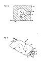
- bladder body 78 may also include a tail portion 102 (viewing Figure 5) whereas the walls of the bladder are closely adjacent during manufacture but prior to filling of the bladder with lubricant 80.
- the tail portion 102 may thus provide an opening for filling of bladder 76 with lubricant, after which the bladder is sealed adhesively or by heat sealing, as depicted at 104.
Landscapes
- Engineering & Computer Science (AREA)
- General Engineering & Computer Science (AREA)
- Mechanical Engineering (AREA)
- Chemical & Material Sciences (AREA)
- Combustion & Propulsion (AREA)
- Oil, Petroleum & Natural Gas (AREA)
- Turbine Rotor Nozzle Sealing (AREA)
- Lubricants (AREA)
- Nozzles (AREA)
- Lubrication Of Internal Combustion Engines (AREA)
- Coating Apparatus (AREA)
Applications Claiming Priority (2)
| Application Number | Priority Date | Filing Date | Title |
|---|---|---|---|
| US806587 | 1985-12-09 | ||
| US06/806,587 US4697414A (en) | 1985-12-09 | 1985-12-09 | Lubrication apparatus |
Publications (2)
| Publication Number | Publication Date |
|---|---|
| EP0226424A2 true EP0226424A2 (de) | 1987-06-24 |
| EP0226424A3 EP0226424A3 (de) | 1988-08-10 |
Family
ID=25194381
Family Applications (1)
| Application Number | Title | Priority Date | Filing Date |
|---|---|---|---|
| EP86309538A Withdrawn EP0226424A3 (de) | 1985-12-09 | 1986-12-08 | Anordnung und Verfahren zum Verteilen von Flüssigkeit |
Country Status (4)
| Country | Link |
|---|---|
| US (1) | US4697414A (de) |
| EP (1) | EP0226424A3 (de) |
| JP (1) | JPS62137494A (de) |
| IL (1) | IL80897A0 (de) |
Cited By (1)
| Publication number | Priority date | Publication date | Assignee | Title |
|---|---|---|---|---|
| EP3242069A1 (de) * | 2016-05-04 | 2017-11-08 | Poly-clip System GmbH & Co. KG | Kartuschenvorrichtung zur schmierung einer maschine |
Families Citing this family (17)
| Publication number | Priority date | Publication date | Assignee | Title |
|---|---|---|---|---|
| US4913196A (en) * | 1987-05-20 | 1990-04-03 | Surgikos, Inc. | Fluid injection system pumping methods |
| US4817800A (en) * | 1987-05-20 | 1989-04-04 | Surgikos, Inc. | Fluid injection system cassette and fluid packaging methods |
| US4941518A (en) * | 1987-05-20 | 1990-07-17 | Johnson & Johnson Medical, Inc. | Fluid injection system |
| US6076496A (en) * | 1997-08-06 | 2000-06-20 | Technology Licensing Company | Captive bag engine pre-oiling apparatus |
| US6076497A (en) * | 1997-08-06 | 2000-06-20 | Technology Licensing Company | Pressurized containers using phase change system |
| US7216473B1 (en) * | 1999-07-09 | 2007-05-15 | Hamilton Sundstrand Corporation | Turbojet engine lubrication system |
| US6986324B2 (en) | 2001-10-19 | 2006-01-17 | Hydropac/Lab Products, Inc. | Fluid delivery valve system and method |
| US9763425B2 (en) | 2001-10-19 | 2017-09-19 | Hydropac/Lab Products, Inc. | Method and system of providing sealed bags of fluid at the clean side of a laboratory facility |
| EP1958501A3 (de) * | 2001-10-19 | 2009-03-04 | Hydropac/Lap Products, Inc. | Fluidzufuhrsystem |
| US6983721B2 (en) * | 2001-10-19 | 2006-01-10 | Hydropac/Lab Products, Inc. | Method and system of providing sealed bags of fluid at the clean side of a laboratory facility |
| JP4689515B2 (ja) * | 2006-03-30 | 2011-05-25 | Thk株式会社 | 運動案内装置用潤滑剤充填容器 |
| US8627705B2 (en) * | 2009-02-26 | 2014-01-14 | Belvac Production Machinery, Inc. | Self compensating sliding air valve mechanism |
| US8651240B1 (en) | 2012-12-24 | 2014-02-18 | United Technologies Corporation | Pressurized reserve lubrication system for a gas turbine engine |
| US9127567B2 (en) | 2012-06-29 | 2015-09-08 | United Technologies Corporation | Non-interrupted turbomachine fluid supply |
| US10458330B2 (en) | 2014-01-20 | 2019-10-29 | United Technologies Corporation | Auxiliary oil system for geared gas turbine engine |
| US10391541B2 (en) | 2014-02-27 | 2019-08-27 | Belvac Production Machinery, Inc. | Recirculation systems and methods for can and bottle making machinery |
| CN114877233B (zh) * | 2022-04-01 | 2023-09-19 | 山东固丝德夫金属制品有限公司 | 一种钢丝绳淋浸涂油装置 |
Family Cites Families (18)
| Publication number | Priority date | Publication date | Assignee | Title |
|---|---|---|---|---|
| DE951790C (de) * | 1952-05-11 | 1956-10-31 | California Research Corp | Entleerungsvorrichtung fuer Metallbehaelter |
| US3075035A (en) * | 1960-01-26 | 1963-01-22 | Yardney International Corp | Fluid-discharge device |
| FR1342107A (fr) * | 1960-04-27 | 1963-11-08 | Dispositif de lubrification à graisse | |
| US3206261A (en) * | 1962-04-04 | 1965-09-14 | Franklin Electric Co Inc | Grease feed device |
| US3231317A (en) * | 1963-03-28 | 1966-01-25 | Walter H Dudar | Emergency lubrication systems for bearings, journal boxes, and the like |
| GB1121611A (en) * | 1964-08-11 | 1968-07-31 | Bristol Siddeley Engines Ltd | Lubrication of bearings |
| DE1536003A1 (de) * | 1965-05-03 | 1969-10-16 | Dow Chemical Co | Abgabegeraet fuer breiige oder halbfluessige Massen |
| US3637048A (en) * | 1969-09-22 | 1972-01-25 | Carrier Corp | Auxiliary lubricating system |
| US4002224A (en) * | 1975-02-26 | 1977-01-11 | Westinghouse Electric Corporation | Turbine lubrication and emergency gas system |
| US4105093A (en) * | 1977-02-03 | 1978-08-08 | Westinghouse Electric Corp. | Control system for pressurized lubricating system |
| US4153141A (en) * | 1977-06-20 | 1979-05-08 | General Electric Company | Auxiliary oil supply system |
| US4157744A (en) * | 1977-07-18 | 1979-06-12 | Capriotti Lawrence J | Lubricating and cooling engine system component |
| SU731170A1 (ru) * | 1978-01-31 | 1980-04-30 | Предприятие П/Я В-2504 | Система смазки подшипников |
| US4284174A (en) * | 1979-04-18 | 1981-08-18 | Avco Corporation | Emergency oil/mist system |
| FR2465079A1 (fr) * | 1979-09-17 | 1981-03-20 | Snecma | Dispositif de graissage de secours par aerosol notamment pour engins volants |
| US4359140A (en) * | 1980-07-07 | 1982-11-16 | Shreve James S | Engine auxiliary oiler |
| US4385714A (en) * | 1980-11-25 | 1983-05-31 | Miklos Szabo | Apparatus for and method of spreading gaseous, liquid and powdered materials |
| US4390082A (en) * | 1980-12-18 | 1983-06-28 | Rotoflow Corporation | Reserve lubricant supply system |
-
1985
- 1985-12-09 US US06/806,587 patent/US4697414A/en not_active Expired - Fee Related
-
1986
- 1986-11-26 JP JP61283029A patent/JPS62137494A/ja active Pending
- 1986-12-07 IL IL80897A patent/IL80897A0/xx unknown
- 1986-12-08 EP EP86309538A patent/EP0226424A3/de not_active Withdrawn
Cited By (3)
| Publication number | Priority date | Publication date | Assignee | Title |
|---|---|---|---|---|
| EP3242069A1 (de) * | 2016-05-04 | 2017-11-08 | Poly-clip System GmbH & Co. KG | Kartuschenvorrichtung zur schmierung einer maschine |
| CN107435806A (zh) * | 2016-05-04 | 2017-12-05 | 复合夹具系统两合公司 | 用于润滑机器的盒式装置 |
| US10663111B2 (en) | 2016-05-04 | 2020-05-26 | Poly-Clip System Gmbh & Co. Kg | Cartridge device for lubricating a machine |
Also Published As
| Publication number | Publication date |
|---|---|
| JPS62137494A (ja) | 1987-06-20 |
| US4697414A (en) | 1987-10-06 |
| IL80897A0 (en) | 1987-03-31 |
| EP0226424A3 (de) | 1988-08-10 |
Similar Documents
| Publication | Publication Date | Title |
|---|---|---|
| EP0226424A2 (de) | Anordnung und Verfahren zum Verteilen von Flüssigkeit | |
| US4741155A (en) | Lubrication method and apparatus | |
| US5809771A (en) | Aircraft engine fuel system | |
| US5845483A (en) | Windmill engine starting system with fluid driven motor and pump | |
| KR101869856B1 (ko) | 파워 변속기 및 항공기 | |
| US20220136442A1 (en) | Systems and methods for preventing fuel leakage in a gas turbine engine | |
| US4717000A (en) | Integrated emergency lubrication system | |
| US5235812A (en) | Integrated power unit | |
| US6877306B2 (en) | Nozzle assembly with flow divider and ecology valve | |
| EP3670863B1 (de) | Hilfsschmiersystem mit durchflussverwaltungsventil | |
| US3722623A (en) | Preliminary lubrication device | |
| US20040025511A1 (en) | Rapid shutdown and ecology system | |
| US20140331639A1 (en) | Turbomachine Lubrication System with an Anti-Siphon Valve for Windmilling | |
| US20050135929A1 (en) | Pressurized oil supply for propeller engine system | |
| US4373421A (en) | Emergency aerosol lubrication device, particularly for airborne engines | |
| GB1597404A (en) | Auxiliary oil supply systems | |
| US11542845B2 (en) | Aircraft engine lubrication system and method | |
| US4433539A (en) | Means for controlling air scavenge pressure in the bearing compartment of gas turbines | |
| US3100964A (en) | Water injection system for a multistage compressor | |
| US5060469A (en) | Integrated power unit control apparatus and method | |
| US5274992A (en) | Integrated power unit combustion apparatus and method | |
| US20120036866A1 (en) | Auxiliary power unit with multiple fuel sources | |
| US4149372A (en) | Fuel reclaiming system | |
| CN111271190B (zh) | 一种冲压空气涡轮微流温控循环结构 | |
| CN210105991U (zh) | 辅助喷射系统、发动机、动力总成 |
Legal Events
| Date | Code | Title | Description |
|---|---|---|---|
| PUAI | Public reference made under article 153(3) epc to a published international application that has entered the european phase |
Free format text: ORIGINAL CODE: 0009012 |
|
| AK | Designated contracting states |
Kind code of ref document: A2 Designated state(s): DE FR GB IT SE |
|
| PUAL | Search report despatched |
Free format text: ORIGINAL CODE: 0009013 |
|
| AK | Designated contracting states |
Kind code of ref document: A3 Designated state(s): DE FR GB IT SE |
|
| STAA | Information on the status of an ep patent application or granted ep patent |
Free format text: STATUS: THE APPLICATION IS DEEMED TO BE WITHDRAWN |
|
| 18D | Application deemed to be withdrawn |
Effective date: 19890211 |
|
| RIN1 | Information on inventor provided before grant (corrected) |
Inventor name: MCCARTY, ROBERT S. |