EP0226476B1 - Dispositif de mesure de tension d'une installation blindée haute tension - Google Patents
Dispositif de mesure de tension d'une installation blindée haute tension Download PDFInfo
- Publication number
- EP0226476B1 EP0226476B1 EP86402121A EP86402121A EP0226476B1 EP 0226476 B1 EP0226476 B1 EP 0226476B1 EP 86402121 A EP86402121 A EP 86402121A EP 86402121 A EP86402121 A EP 86402121A EP 0226476 B1 EP0226476 B1 EP 0226476B1
- Authority
- EP
- European Patent Office
- Prior art keywords
- compartment
- enclosure
- orifice
- measuring device
- filling
- Prior art date
- Legal status (The legal status is an assumption and is not a legal conclusion. Google has not performed a legal analysis and makes no representation as to the accuracy of the status listed.)
- Expired - Lifetime
Links
- 238000009434 installation Methods 0.000 title claims abstract description 18
- 239000003990 capacitor Substances 0.000 claims abstract description 35
- 239000004020 conductor Substances 0.000 claims description 12
- 238000007789 sealing Methods 0.000 claims description 6
- 238000005259 measurement Methods 0.000 abstract description 3
- 230000000994 depressogenic effect Effects 0.000 description 3
- 238000000926 separation method Methods 0.000 description 3
- 229910018503 SF6 Inorganic materials 0.000 description 2
- SFZCNBIFKDRMGX-UHFFFAOYSA-N sulfur hexafluoride Chemical compound FS(F)(F)(F)(F)F SFZCNBIFKDRMGX-UHFFFAOYSA-N 0.000 description 2
- 229960000909 sulfur hexafluoride Drugs 0.000 description 2
- 241001080024 Telles Species 0.000 description 1
- 238000006073 displacement reaction Methods 0.000 description 1
- 229940082150 encore Drugs 0.000 description 1
- 238000004519 manufacturing process Methods 0.000 description 1
- 239000002184 metal Substances 0.000 description 1
- 230000000717 retained effect Effects 0.000 description 1
Images

Classifications
-
- G—PHYSICS
- G01—MEASURING; TESTING
- G01R—MEASURING ELECTRIC VARIABLES; MEASURING MAGNETIC VARIABLES
- G01R15/00—Details of measuring arrangements of the types provided for in groups G01R17/00 - G01R29/00, G01R33/00 - G01R33/26 or G01R35/00
- G01R15/04—Voltage dividers
- G01R15/06—Voltage dividers having reactive components, e.g. capacitive transformer
-
- H—ELECTRICITY
- H02—GENERATION; CONVERSION OR DISTRIBUTION OF ELECTRIC POWER
- H02B—BOARDS, SUBSTATIONS OR SWITCHING ARRANGEMENTS FOR THE SUPPLY OR DISTRIBUTION OF ELECTRIC POWER
- H02B13/00—Arrangement of switchgear in which switches are enclosed in, or structurally associated with, a casing, e.g. cubicle
- H02B13/02—Arrangement of switchgear in which switches are enclosed in, or structurally associated with, a casing, e.g. cubicle with metal casing
- H02B13/035—Gas-insulated switchgear
- H02B13/0356—Mounting of monitoring devices, e.g. current transformers
Definitions
- the invention relates to a device for measuring the voltage of a high voltage conductor, arranged in a sealed enclosure filled with a gas of high dielectric strength, in particular of a shielded high voltage installation, comprising a capacitive divider constituted by a high voltage capacitor, and a low voltage capacitor connected in series, the high voltage capacitor being disposed in said enclosure and comprising said conductor and an electrode surrounding said conductor and the low voltage capacitor being disposed in a sealed compartment outside said enclosure by being electrically connected to said electrode by a conductor passing through the wall of the enclosure, the sealed compartment and the enclosure communicating through a communication orifice.
- Document DE-A 3 243 342 describes a measuring device of the kind mentioned which comprises a low voltage capacitor disposed in a compartment permanently communicating with the enclosure of the shielded installation. This frees up inaccuracies due to variations in temperature and pressure, which simultaneously influence the high voltage capacitor and the low voltage capacitor arranged in the same gas volume.
- the low voltage capacitor is a fragile element and intervention or repair may be necessary periodically. In this case, the entire installation must be switched off and emptied to give access to this low voltage capacitor.
- These emptying operations which subsequently require re-vacuuming and filling with sulfur hexafluoride, are delicate and complicated.
- the object of the present invention is to allow the production of a measuring device with a capacitive divider allowing easy access to the low voltage capacitor while avoiding variations due to the temperature or pressure of the gas in the installation.
- the measuring device is characterized in that the sealed compartment of the low-voltage capacitor comprises a gas filling orifice and that the communication orifice and the filling orifice are provided with valves for placing said communication in communication. compartment selectively with the enclosure and with a filling duct connected to the filling orifice.
- the low voltage capacitor housing compartment In normal operation, the low voltage capacitor housing compartment is in permanent communication with the enclosure containing the high voltage capacitor of the capacitive divider and any pressure and / or temperature variation is automatically transmitted to the compartment, so as to avoid any influence on measure. Housing in a separate compartment makes it possible to isolate the latter from the installation enclosure by simply closing a valve associated with the communication orifice to allow intervention in this compartment. Subsequently, it is of course necessary to create a vacuum in this compartment before putting it back in communication with the enclosure, but this intervention is limited and much simpler than the operation aimed at completely filling the enclosure. The quantities of gas handled are significantly lower and the risks of leaks or pollution are significantly reduced.
- the housing in a separate compartment of the low-voltage capacitor allows other elements of the measuring device to be incorporated into this housing.
- valve of the communication orifice is urged into the closed position, the opening control being actuated by the installation of a cover for closing the filling orifice. It is thus ensured that the compartment is sealed before it is placed in communication with the enclosure of the shielded installation.
- the removal of the obturator cover conversely causes the automatic closing of the valve of the communication orifice as well as the dismantling of the compartment access cover.
- the control of the communication orifice valve advantageously comprises a sliding rod which cooperates with a pusher passing in a sealed manner through the compartment cover.
- the shutter cover is arranged to engage at the end of the shutter stroke the external part of the pusher and move the latter in the opening direction of the valve of the communication orifice.
- the establishment of a filling duct on the coupler associated with the filling orifice does not activate the aforementioned pusher so as to allow emptying and filling of the compartment, the latter remaining isolated from the enclosure.
- the coupler of the filling orifice advantageously comprises a shutter valve urged into the closed position and moved into the open position by the connection of the filling conduit. This arrangement prevents any leakage during the connection and disconnection operations and the installation of the shutter of the filling orifice.
- the low voltage capacitor can be of any type with a capacity varying with temperature in the same way as that of the high voltage capacitor.
- an enclosure 10 of a high-voltage shielded installation is filled with a gas with high dielectric strength, for example pressurized sulfur hexafluoride (SF 6 ).
- a gas with high dielectric strength for example pressurized sulfur hexafluoride (SF 6 ).
- the envelope 12 of the enclosure 10 is cylindrical and coaxially surrounds a conductor 14, for example a bar under high voltage.
- a cylindrical electrode 16 which constitutes with bar 14 a high voltage capacitor whose dielectric is SF s .
- a nozzle 18 which confines a sealed compartment 20.
- a low voltage capacitor 36 one of which 38 of the electrodes is connected to earth, for example to the metal wall of the end piece 18 and the other electrode 40 of which is connected on the one hand by a conductor 42 sealingly passes through the wall 22 to the cylindrical electrode 16 of the high-voltage capacitor and on the other hand by a conductor 44 passing through the wall of the end piece 18 to a measuring device 46.
- the cover 32 carries a coupler 48 having a filling orifice 50, equipped with a valve 52, biased in the closed position by a spring 54.
- On the coupler 48 can be fixed, for example by screwing, a shutter cover 56 ensuring a double sealing, as well as the control of the valve 28 in the manner described below. Only the control of one of the valves 28 is described, the other being identical.
- the cover 32 carries a guide sleeve 58 disposed opposite the valve 28 of the communication orifice 26. In the sleeve 58 is mounted with sealed sliding a pusher 60 carrying on its internal part to the compartment 20 a control rod 62 whose l the free end cooperates with the valve 28 of the communication orifice.
- the head 64 of the pusher 60 disposed outside the compartment 20 cooperates with a plate 66, capable of displacement, limited by guide screws 67, in the sliding direction of the pusher 60.
- An adjustment screw 68 is interposed between the head 64 of the pusher 60 and the movable plate 66.
- the pusher 60 In the position of separation of the plate 66 from the cover 32, shown in FIG. 2, the pusher 60 is in the raised position and the valve 28 is in the closed closing position. the communication orifice 26.
- the depressed pusher 60 actuates by its rod 62 the valve 28 towards the open position of the communication orifice 26.
- the head 64 carries a toric sealing ring 70 which is applied to the cover 32 in the depressed position of the pusher 60 to ensure a double sealing of the compartment 20.
- the movable plate 66 has an opening 72 through which the coupler 48 passes.
- the connector 76 is equipped with a shutter valve 78, biased in position closing by a spring 80 and arranged to cooperate with the valve 52 to release the communication during the installation of the filling duct 74.
- a shutter valve 78 biased in position closing by a spring 80 and arranged to cooperate with the valve 52 to release the communication during the installation of the filling duct 74.
- Such couplers with automatic closure during a disconnection and conversely with automatic opening of the communication during of a connection are well known to specialists.
- the connector 76 is arranged so as not to actuate the movable plate 66 during the connection maneuver in order to avoid any untimely opening of the valve 28 of the communication orifice 26.
- the filling duct can in this case be permanently fixed, any other type of coupler that can also be used.
Landscapes
- Engineering & Computer Science (AREA)
- Power Engineering (AREA)
- Physics & Mathematics (AREA)
- General Physics & Mathematics (AREA)
- Fixed Capacitors And Capacitor Manufacturing Machines (AREA)
- Measuring Fluid Pressure (AREA)
- Measuring Instrument Details And Bridges, And Automatic Balancing Devices (AREA)
- Transformers For Measuring Instruments (AREA)
- Details Of Television Scanning (AREA)
- Measuring Leads Or Probes (AREA)
- Measurement Of Current Or Voltage (AREA)
- Arrangements For Transmission Of Measured Signals (AREA)
- Measuring And Recording Apparatus For Diagnosis (AREA)
Description
- L'invention est relative à un dispositif de mesure de la tension d'un conducteur haute tension, disposé dans une enceinte étanche remplie d'un gaz à rigidité diélectrique élevée, notamment d'une installation blindée haute tension, comprenant un diviseur capacitif constitué par un condensateur haute tension, et un condensateur basse tension connectés en série, le condensateur haute tension étant disposé dans ladite enceinte et comprenant ledit conducteur et une électrode entourant ledit conducteur et le condensateur basse tension étant disposé dans un compartiment étanche à l'extérieur de ladite enceinte en étant relié électriquement à ladite électrode par un conducteur traversant la paroi de l'enceinte, le compartiment étanche et l'enceinte communiquant par un orifice de communication.
- Le document DE-A 3 243 342 décrit un dispositif de mesure du genre mentionné qui comporte un condensateur basse tension disposé dans un compartiment communiquant en permanence avec l'enceinte de l'installation blindée. On s'affranchit ainsi des imprécisions dues aux variations de température et de pression, lesquelles influencent en même temps le condensateur haute tension et le condensateur basse tension disposés dans le même volume gazeux. Le condensateur basse tension est un élément fragile et une intervention ou réparation peut s'imposer périodiquement. Dans ce cas, l'ensemble de l'installation doit être mis hors circuit et vidé pour donner accès à ce condensateur basse tension. Ces opérations de vidange, qui nécessitent par la suite une remise sous vide et un remplissage à l'hexafluorure de soufre, sont délicates et compliquées.
- Le but de la présente invention est de permettre la réalisation d'un dispositif de mesure à diviseur capacitif permettant un accès aisé au condensateur basse tension tout en évitant les variations dues à la température ou à la pression du gaz de l'installation.
- Le dispositif de mesure selon l'invention est caractérisé en ce que le compartiment étanche du condensateur basse tension comprend un orifice de remplissage de gaz et que l'orifice de communication et l'orifice de remplissage sont munis de clapets pour la mise en communication dudit compartiment sélectivement avec l'enceinte et avec un conduit de remplissage connecté à l'orifice de remplissage.
- En fonctionnement normal, le compartiment de logement du condensateur basse tension est en communication permanente avec l'enceinte contenant le condensateur haute tension du diviseur capacitif et toute variation de pression et/ou de température est automatiquement transmise au compartiment, de manière à éviter toute influence sur la mesure. Le logement dans un compartiment séparé permet d'isoler ce dernier de l'enceinte de l'installation par simple fermeture d'un clapet associé à l'orifice de communication pour permettre une intervention dans ce compartiment. Par la suite, il convient bien entendu de faire le vide dans ce compartiment avant de le remettre en communication avec l'enceinte mais cette intervention est limitée et nettement plus simple que l'opération visant le remplissage complet de l'enceinte. Les quantités de gaz manipulées sont notablement inférieures et les risques de fuites ou de pollution sont notablement réduits.
- Le logement dans un compartiment séparé du condensateur basse tension permet d'incorporer dans ce logement d'autres éléments du dispositif de mesure.
- Afin d'éviter toute fausse manoeuvre, le clapet de l'orifice de communication est sollicité en position de fermeture, la commande d'ouverture étant actionnée par la mise en place d'un capot d'obturation de l'orifice de remplissage. On est ainsi assuré d'une fermeture étanche du compartiment avant sa mise en communication avec l'enceinte de l'installation blindée. L'enlèvement du capot obturateur provoque inversement la fermeture automatique du clapet de l'orifice de communication ainsi d'ailleurs que le démontage du couvercle d'accès au compartiment. La commande du clapet de l'orifice de communication comporte avantageusement une tige coulissante qui coopère avec un poussoir traversant d'une manière étanche le couvercle du compartiment. Le capot obturateur est agencé pour engager en fin de course d'obturation la partie externe du poussoir et déplacer ce dernier dans la direction d'ouverture du clapet de l'orifice de communication. La mise en place d'un conduit de remplissage sur le coupleur associé à l'orifice de remplissage n'actionne pas le poussoir précité de façon à permettre une vidange et un remplissage du compartiment, ce dernier restant isolé de l'enceinte. Le coupleur de l'orifice de remplissage comporte avantageusement un clapet d'obturation sollicité en position de fermeture et déplacé en position d'ouverture par la connexion du conduit de remplissage. Cette disposition évite toute fuite au cours des manoeuvres de connexion et de déconnexion et de mise en place de l'obturateur de l'orifice de remplissage.
- Le condensateur basse tension peut être d'un type quelconque d'une capacité variant avec la température de la même façon que celle du condensateur haute tension.
- D'autres avantages et caractéristiques ressortiront plus clairement de la description qui va suivre d'un mode de mise en oeuvre de l'invention, donné à titre d'exemple non limitatif et représenté aux dessins annexés, dans lesquels :
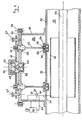
- - la figure 1 est une vue schématique en coupe axiale d'un dispositif de mesure selon l'invention, représenté en position normale de fonctionnement ;
- - la figure 2 est une vue analogue à celle de la figure 1, montrant le dispositif de mesure pendant la phase de vidange du compartiment de logement du condensateur basse tension.
- Sur les figures, une enceinte 10 d'une installation blindée à haute tension est remplie d'un gaz à rigidité diélectrique élevée, par exemple de l'hexafluorure de soufre sous pression (SF6). Dans l'exemple représenté sur les figures, l'enveloppe 12 de l'enceinte 10 est cylindrique et entoure coaxialement un conducteur 14, par exemple une barre sous haute tension. Entre l'enveloppe 12 et la barre 14 est intercalée une électrode cylindrique 16 qui constitue avec la barre 14 un condensateur haute tension dont le diélectrique est le SFs. A l'extérieur de l'enveloppe 12 est fixé un embout 18 qui confine un compartiment étanche 20. Dans la paroi 22 de séparation du compartiment 20 de l'enceinte 10 sont fixés deux coupleurs 24 présentant chacun un orifice de communication 26, susceptibles d'être obturés par un clapet 28, sollicité en position de fermeture par un ressort 30. L'embout 18 est fermé du côté opposé à la paroi 22 par un couvercle 32, maintenu par des vis de serrage 34 avec interposition de joints d'étanchéité non représentés. Dans le compartiment 20 est logé un condensateur basse tension 36, dont l'une 38 des électrodes est connectée à la terre, par exemple à la paroi métallique de l'embout 18 et dont l'autre électrode 40 est connectée d'une part par un conducteur 42 traversant d'une manière étanche la paroi 22 à l'électrode cylindrique 16 du condensateur haute tension et d'autre part par un conducteur 44 traversant la paroi de l'embout 18 à un appareil de mesure 46. Il est facile de voir que la connexion en série du condensateur haute tension 14, 16 et du condensateur basse tension 38, 40, constitue un diviseur capacitif bien connu des spécialistes permettant une mesure de la tension du conducteur 14. Il est inutile de décrire en détails de tels diviseurs capacitifs, notamment l'appareil de mesure 46 qui peut être d'un type quelconque.
- Le couvercle 32 porte un coupleur 48 présentant un orifice de remplissage 50, équipé d'un clapet 52, sollicité en position de fermeture par un ressort 54. Sur le coupleur 48 peut être fixé, par exemple par vissage, un capot obturateur 56 assurant une double étanchéité, ainsi que la commande du clapet 28 de la manière décrite ci-dessous. Seule la commande de l'un des clapets 28 est décrite, l'autre étant identique. Le couvercle 32 porte un manchon de guidage 58 disposé en regard du clapet 28 de l'orifice de communication 26. Dans le manchon 58 est monté à coulissement étanche un poussoir 60 portant sur sa partie interne au compartiment 20 une tige de commande 62 dont l'extrémité libre coopère avec le clapet 28 de l'orifice de communication. La tête 64 du poussoir 60, disposée à l'extérieur du compartiment 20 coopère avec une plaque 66, susceptible d'un déplacement, limité par des vis de guidage 67 ,dans la direction de coulissement du poussoir 60. Une vis de réglage 68, est intercalée entre la tête 64 du poussoir 60 et la plaque mobile 66. En position d'écartement de la plaque 66 du couvercle 32, représentée la figure 2, le poussoir 60 est en position relevée et le clapet 28 est en position de fermeture de l'orifice de communication 26. En position rapprochée de la plaque 66 du couvercle 32, représentée à la figure 1, le poussoir 60 enfoncé actionne par sa tige 62 le clapet 28 vers la position d'ouverture de l'orifice de communication 26. La tête 64 porte un anneau torique d'étanchéité 70 venant s'appliquer sur le couvercle 32 en position enfoncée du poussoir 60 pour assurer une double étanchéité du compartiment 20. La plaque mobile 66 présente une ouverture 72 traversée par le coupleur 48.
- En se référant à la figure 1, on voit que lors de la mise en place du capot obturateur 56 sur le coupleur 48, le bord de ce capot 56 engage la plaque mobile 66 et pousse cette dernière en position rapprochée du couvercle 32 provoquant l'ouverture du clapet de communication 28. L'enlèvement du capot obturateur 56 autorise par contre un écartement de la plaque mobile 66 du couvercle 32 sous l'action du ressort de rappel 30 du clapet 28 et une fermeture de ce dernier. Après enlèvement du capot obturateur 56, on peut fixer, par exemple par vissage ou clipsage sur le coupleur 48, un connecteur 76 d'un conduit de remplissage 74. Le connecteur 76 est équipé d'un clapet d'obturation 78, sollicité en position de fermeture par un ressort 80 et agencé pour coopèrer avec le clapet 52 pour libérer la communication lors de la mise en place du conduit de remplissage 74. De tels coupleurs à obturation automatique lors d'une déconnexion et inversement à ouverture automatique de la communication lors d'une connexion sont bien connus des spécialistes. Le connecteur 76 est agencé pour ne pas actionner la plaque mobile 66 pendant la manoeuvre de connexion afin d'éviter toute ouverture intempestive du clapet 28 de l'orifice de communication 26.
- Le dispositif de mesure selon l'invention fonctionne de la manière suivante :
- - dans la position de fonctionnement normal, le coupleur 48 est coiffé par le capot obturateur 56 poussant la plaque mobile 66 en direction d'ouverture des clapets 28 des orifices de communication 26. Dans cette position représentée à la figure 1, le compartiment 20 est en communication avec l'enceinte 10, l'étanchéité du compartiment 20 vers l'extérieur étant assurée au niveau du coupleur 48, d'une part par le clapet 52 fermé et d'autre part par le capot obturateur 56. Les poussoirs enfoncés 60 comportent également une double étanchéité limitant les risques de fuites. Les communications assurées par les orifices 26 évitent toute différence de pression ou de température entre le compartiment 20 et l'enceinte 10 et la mesure du diviseur capacitif 14, 16, n'est pas affectée par de telles variations de température ou de pression, si l'on choisit un condensateur 36 variant avec la température de la même façon que le condensateur 14, 16.
- - lors d'un incident, par exemple d'une défaillance du condensateur basse tension 36, on enlève le capot obturateur 56 qui libère la plaque mobile 66 venant en position écartée permettant la fermeture des clapets 28 des orifices de communication 26. Par la suite, on met en place le conduit de remplissage 74 de la manière représentée à la figure 2. La connexion du conduit de remplissage 74 provoque l'ouverture du clapet 52 de l'orifice de remplissage 50, les clapets 28 des orifices de communication 26 restant fermés Le gaz du compartiment 20 peut être évacué par le conduit de remplissage 74 en étant, soit récupéré, soit rejeté dans l'atmosphère. Après vidange du compartiment 20, le couvercle 32 peut être enlevé par dévissage des vis 34 pour donner accès au condensateur 36. Le remplissage de l'enceinte 10 est conservé pendant cette opération et l'installation peut éventuellement rester sous tension si l'on prend certaines précautions. La réparation étant effectuée, il suffit de refixer le couvercle 32 et de mettre sous vide et par la suite remplir de gaz le compartiment 20. Cette opération étant terminée, le conduit de remplissage 74 est déconnecté avec fermeture automatique du clapet 52 de l'orifice de remplissage 50. La mise en place du capot obturateur 56 provoque à nouveau l'ouverture des clapets 28 des orifices de communication 26 mettant l'installation dans la position d'origine, illustrée par la figure 1. Un démontage intempestif du couvercle 32, le capot obturateur 56 étant encore en place, provoque également la fermeture des clapets 28 des orifices de communication 26 limitant l'échappement de gaz de l'enceinte 10.
- Il est clair qu'on ne sortirait pas du cadre de l'invention en prévoyant une commande manuelle du clapet 28 de l'orifice communication 26, la commande automatique ayant pour avantage d'éviter toute fausse manoeuvre et des consignes astreignantes. Le conduit de remplissage peut dans ce cas être fixé en permanence, tout autre type de coupleur pouvant d'ailleurs être utilisé.
Claims (8)
Priority Applications (1)
| Application Number | Priority Date | Filing Date | Title |
|---|---|---|---|
| AT86402121T ATE59481T1 (de) | 1985-10-14 | 1986-09-29 | Spannungsmessschaltung fuer eine abgeschirmte hochspannungseinrichtung. |
Applications Claiming Priority (2)
| Application Number | Priority Date | Filing Date | Title |
|---|---|---|---|
| FR8515301A FR2588666B1 (fr) | 1985-10-14 | 1985-10-14 | Dispositif de mesure de tension d'une installation blindee haute tension. |
| FR8515301 | 1985-10-14 |
Publications (2)
| Publication Number | Publication Date |
|---|---|
| EP0226476A1 EP0226476A1 (fr) | 1987-06-24 |
| EP0226476B1 true EP0226476B1 (fr) | 1990-12-27 |
Family
ID=9323857
Family Applications (1)
| Application Number | Title | Priority Date | Filing Date |
|---|---|---|---|
| EP86402121A Expired - Lifetime EP0226476B1 (fr) | 1985-10-14 | 1986-09-29 | Dispositif de mesure de tension d'une installation blindée haute tension |
Country Status (9)
| Country | Link |
|---|---|
| US (1) | US4739254A (fr) |
| EP (1) | EP0226476B1 (fr) |
| JP (1) | JPH0695103B2 (fr) |
| CN (1) | CN1007017B (fr) |
| AT (1) | ATE59481T1 (fr) |
| CA (1) | CA1256496A (fr) |
| DE (1) | DE3676661D1 (fr) |
| FR (1) | FR2588666B1 (fr) |
| IN (1) | IN168584B (fr) |
Families Citing this family (6)
| Publication number | Priority date | Publication date | Assignee | Title |
|---|---|---|---|---|
| DE19923211C2 (de) * | 1998-07-23 | 2001-05-10 | Karlsruhe Forschzent | Kapazitiver Spannungsteiler zur Messung von Hochspannungsimpulsen mit Millisekunden-Impulsdauer |
| DE102008024730A1 (de) * | 2008-05-19 | 2009-11-26 | Siemens Aktiengesellschaft | Anordnung mit einer gasdichten Messdurchführung |
| US8163574B2 (en) * | 2009-05-08 | 2012-04-24 | Eaton Corporaton | System and method for sensing voltage in medium-to-high voltage applications |
| CN101576579B (zh) * | 2009-06-01 | 2011-01-05 | 西安交通大学 | 用于纳秒级高压脉冲测量的同轴-对称分立型电容分压器 |
| CN101814370A (zh) * | 2010-04-09 | 2010-08-25 | 江苏雷宇高电压设备有限公司 | 一种高精度分压器 |
| FR3056344B1 (fr) * | 2016-09-20 | 2023-08-04 | Mft Dappareillage Electrique De Cahors | Appareil electrique moyenne ou haute tension sous atmosphere protectrice avec instrumentation par couplage capacitif, adaptateur pour un tel appareil, procede de montage et d'utilisation |
Family Cites Families (13)
| Publication number | Priority date | Publication date | Assignee | Title |
|---|---|---|---|---|
| US1433416A (en) * | 1921-03-14 | 1922-10-24 | William B Scott | Regulator |
| GB325967A (en) * | 1929-01-30 | 1930-03-06 | Ig Farbenindustrie Ag | Improvements in the manufacture and production of colouring materials for colouring materials of the nature of rubber |
| US1875732A (en) * | 1929-09-03 | 1932-09-06 | British Insulated Cables Ltd | Sealing device for use with electric cables and other apparatus |
| US3652777A (en) * | 1970-03-16 | 1972-03-28 | Electrical Constructors And As | Automatic stop joint for pipe-type cable |
| DE2125297B2 (de) * | 1971-05-17 | 1978-11-16 | Siemens Ag, 1000 Berlin Und 8000 Muenchen | Meßwandler für vollisolierte, metallgekapselte Hochspannungsschaltanlagen |
| DE2313401C2 (de) * | 1973-03-17 | 1982-04-22 | Calor-Emag Elektrizitäts-Aktiengesellschaft, 4030 Ratingen | Spannungswandler für metallgekapselte gasisolierte Hochspannungsschaltanlagen |
| DE2325444A1 (de) * | 1973-05-17 | 1974-12-05 | Siemens Ag | Messwandler fuer vollisolierte, metallgekapselte hochspannungsschaltanlagen |
| DE2341073B2 (de) * | 1973-08-10 | 1980-01-10 | Siemens Ag, 1000 Berlin Und 8000 Muenchen | Meßeinrichtung für die Spannung in einer gekapselten Hochspannungsschaltanlage |
| DE2413927C3 (de) * | 1974-03-20 | 1987-10-22 | Siemens AG, 1000 Berlin und 8000 München | Anordnung mit einem Hochspannungskondensator |
| CH627023A5 (fr) * | 1978-03-09 | 1981-12-15 | Bbc Brown Boveri & Cie | |
| JPS5936410B2 (ja) * | 1979-03-16 | 1984-09-04 | 三菱電機株式会社 | ガス絶縁電気装置 |
| JPS5927090A (ja) * | 1982-07-23 | 1984-02-13 | ノ−トン・カンパニ− | プロツパントおよびその製法 |
| CH660923A5 (de) * | 1982-10-29 | 1987-05-29 | Bbc Brown Boveri & Cie | Vorrichtung zur messung der spannung eines hochspannungfuehrenden teils. |
-
1985
- 1985-10-14 FR FR8515301A patent/FR2588666B1/fr not_active Expired
-
1986
- 1986-09-16 CA CA000518309A patent/CA1256496A/fr not_active Expired
- 1986-09-26 IN IN761/MAS/86A patent/IN168584B/en unknown
- 1986-09-29 EP EP86402121A patent/EP0226476B1/fr not_active Expired - Lifetime
- 1986-09-29 DE DE8686402121T patent/DE3676661D1/de not_active Expired - Fee Related
- 1986-09-29 AT AT86402121T patent/ATE59481T1/de not_active IP Right Cessation
- 1986-10-08 US US06/916,569 patent/US4739254A/en not_active Expired - Fee Related
- 1986-10-13 CN CN86107201A patent/CN1007017B/zh not_active Expired
- 1986-10-13 JP JP61242859A patent/JPH0695103B2/ja not_active Expired - Lifetime
Also Published As
| Publication number | Publication date |
|---|---|
| JPH0695103B2 (ja) | 1994-11-24 |
| JPS6293669A (ja) | 1987-04-30 |
| CN1007017B (zh) | 1990-02-28 |
| ATE59481T1 (de) | 1991-01-15 |
| FR2588666B1 (fr) | 1987-12-11 |
| CN86107201A (zh) | 1987-04-15 |
| CA1256496A (fr) | 1989-06-27 |
| FR2588666A1 (fr) | 1987-04-17 |
| US4739254A (en) | 1988-04-19 |
| EP0226476A1 (fr) | 1987-06-24 |
| DE3676661D1 (de) | 1991-02-07 |
| IN168584B (fr) | 1991-05-04 |
Similar Documents
| Publication | Publication Date | Title |
|---|---|---|
| EP1906424B1 (fr) | Dispositif de contrôle du fonctionnement d'un densimètre pour appareil électrique moyenne et haute tension et procédé de contrôle du fonctionnement d'un densimètre | |
| EP0226476A1 (fr) | Dispositif de mesure de tension d'une installation blindée haute tension | |
| FR2751782A1 (fr) | Disjoncteur a haute tension a auto-soufflage d'arc | |
| FR2400752A1 (fr) | Appareil pour le soudage d'un bouchon de fermeture dans un tube de combustible nucleaire | |
| FR2652426A1 (fr) | Detendeur de bouteille de gaz. | |
| CA2054509C (fr) | Interrupteur rotatif multipolaire | |
| FR2471038A1 (fr) | Dispositif d'assemblage entre deux enceintes d'un appareil electrique de coupure | |
| EP0673098B1 (fr) | Dispositif de contrÔle et de commande pour ligne de transport électrique blindée | |
| FR2789663A1 (fr) | Emballage a controle continu d'etancheite | |
| EP1191564B1 (fr) | Disjoncteur à isolation au gaz avec un transformateur de courant électronique intégré | |
| CA1245697A (fr) | Disjoncteur a gaz sous pression pouvant etre assemble et desassemble sans perte notable de gaz | |
| FR2524960A1 (fr) | Dispositif autonome d'assistance d'une soupape de securite | |
| FR2558562A1 (fr) | Valve pneumatique pilotee | |
| CA1257634A (fr) | Disjoncteur a haute tension a hexafluorure de soufre pouvant fonctionner a des temperatures exterieures basses | |
| EP1729316A1 (fr) | Dispositif de coupure électrique moyenne tension | |
| EP2200060B1 (fr) | Cellule de distribution électrique moyenne tension | |
| EP0789374B1 (fr) | Dispositif de décharge de pression à distance du gaz de remplissage d'un disjoncteur | |
| FR1465587A (fr) | Piège froid à vanne incorporée pour circuit de vide | |
| FR2586136A1 (fr) | Disjoncteur a hexafluorure de soufre a haute densite | |
| FR2734625A1 (fr) | Bloc d'eclairage, notamment bloc autonome pour eclairage de securite | |
| FR2493593A2 (fr) | Dispositif d'assemblage entre deux enceintes d'un appareil electrique de coupure | |
| FR2494033A1 (fr) | Dispositif electrohydraulique de signalisation | |
| FR2629629A1 (fr) | Disjoncteur a haute tension a transformateur de courant incorpore | |
| FR2511554A1 (fr) | Dispositif pour installation de commutation electrique hermetiquement fermee | |
| FR2717636A1 (fr) | Dispositif de détection de fuite de gaz dans une ligne de transport électrique blindée. |
Legal Events
| Date | Code | Title | Description |
|---|---|---|---|
| PUAI | Public reference made under article 153(3) epc to a published international application that has entered the european phase |
Free format text: ORIGINAL CODE: 0009012 |
|
| AK | Designated contracting states |
Kind code of ref document: A1 Designated state(s): AT BE CH DE GB IT LI SE |
|
| 17P | Request for examination filed |
Effective date: 19871009 |
|
| 17Q | First examination report despatched |
Effective date: 19891129 |
|
| GRAA | (expected) grant |
Free format text: ORIGINAL CODE: 0009210 |
|
| AK | Designated contracting states |
Kind code of ref document: B1 Designated state(s): AT BE CH DE GB IT LI SE |
|
| PG25 | Lapsed in a contracting state [announced via postgrant information from national office to epo] |
Ref country code: SE Free format text: THE PATENT HAS BEEN ANNULLED BY A DECISION OF A NATIONAL AUTHORITY Effective date: 19901227 Ref country code: GB Effective date: 19901227 Ref country code: AT Effective date: 19901227 |
|
| REF | Corresponds to: |
Ref document number: 59481 Country of ref document: AT Date of ref document: 19910115 Kind code of ref document: T |
|
| REF | Corresponds to: |
Ref document number: 3676661 Country of ref document: DE Date of ref document: 19910207 |
|
| ITF | It: translation for a ep patent filed | ||
| GBV | Gb: ep patent (uk) treated as always having been void in accordance with gb section 77(7)/1977 [no translation filed] | ||
| ITTA | It: last paid annual fee | ||
| PLBE | No opposition filed within time limit |
Free format text: ORIGINAL CODE: 0009261 |
|
| STAA | Information on the status of an ep patent application or granted ep patent |
Free format text: STATUS: NO OPPOSITION FILED WITHIN TIME LIMIT |
|
| 26N | No opposition filed | ||
| PGFP | Annual fee paid to national office [announced via postgrant information from national office to epo] |
Ref country code: CH Payment date: 19971007 Year of fee payment: 12 |
|
| PGFP | Annual fee paid to national office [announced via postgrant information from national office to epo] |
Ref country code: BE Payment date: 19971118 Year of fee payment: 12 |
|
| PG25 | Lapsed in a contracting state [announced via postgrant information from national office to epo] |
Ref country code: LI Free format text: LAPSE BECAUSE OF NON-PAYMENT OF DUE FEES Effective date: 19980930 Ref country code: CH Free format text: LAPSE BECAUSE OF NON-PAYMENT OF DUE FEES Effective date: 19980930 Ref country code: BE Free format text: LAPSE BECAUSE OF NON-PAYMENT OF DUE FEES Effective date: 19980930 |
|
| BERE | Be: lapsed |
Owner name: MERLIN GERIN Effective date: 19980930 |
|
| REG | Reference to a national code |
Ref country code: CH Ref legal event code: PL |
|
| PGFP | Annual fee paid to national office [announced via postgrant information from national office to epo] |
Ref country code: DE Payment date: 20000912 Year of fee payment: 15 |
|
| PG25 | Lapsed in a contracting state [announced via postgrant information from national office to epo] |
Ref country code: DE Free format text: LAPSE BECAUSE OF NON-PAYMENT OF DUE FEES Effective date: 20020501 |
|
| PG25 | Lapsed in a contracting state [announced via postgrant information from national office to epo] |
Ref country code: IT Free format text: LAPSE BECAUSE OF NON-PAYMENT OF DUE FEES;WARNING: LAPSES OF ITALIAN PATENTS WITH EFFECTIVE DATE BEFORE 2007 MAY HAVE OCCURRED AT ANY TIME BEFORE 2007. THE CORRECT EFFECTIVE DATE MAY BE DIFFERENT FROM THE ONE RECORDED. Effective date: 20050929 |