EP0226703A2 - Capteur électrique de niveau de référence - Google Patents
Capteur électrique de niveau de référence Download PDFInfo
- Publication number
- EP0226703A2 EP0226703A2 EP86110586A EP86110586A EP0226703A2 EP 0226703 A2 EP0226703 A2 EP 0226703A2 EP 86110586 A EP86110586 A EP 86110586A EP 86110586 A EP86110586 A EP 86110586A EP 0226703 A2 EP0226703 A2 EP 0226703A2
- Authority
- EP
- European Patent Office
- Prior art keywords
- electrical
- setpoint generator
- circuit
- output
- actuating element
- Prior art date
- Legal status (The legal status is an assumption and is not a legal conclusion. Google has not performed a legal analysis and makes no representation as to the accuracy of the status listed.)
- Ceased
Links
Images
Classifications
-
- B—PERFORMING OPERATIONS; TRANSPORTING
- B60—VEHICLES IN GENERAL
- B60K—ARRANGEMENT OR MOUNTING OF PROPULSION UNITS OR OF TRANSMISSIONS IN VEHICLES; ARRANGEMENT OR MOUNTING OF PLURAL DIVERSE PRIME-MOVERS IN VEHICLES; AUXILIARY DRIVES FOR VEHICLES; INSTRUMENTATION OR DASHBOARDS FOR VEHICLES; ARRANGEMENTS IN CONNECTION WITH COOLING, AIR INTAKE, GAS EXHAUST OR FUEL SUPPLY OF PROPULSION UNITS IN VEHICLES
- B60K26/00—Arrangement or mounting of propulsion-unit control devices in vehicles
- B60K26/02—Arrangement or mounting of propulsion-unit control devices in vehicles of initiating means or elements
-
- F—MECHANICAL ENGINEERING; LIGHTING; HEATING; WEAPONS; BLASTING
- F02—COMBUSTION ENGINES; HOT-GAS OR COMBUSTION-PRODUCT ENGINE PLANTS
- F02D—CONTROLLING COMBUSTION ENGINES
- F02D11/00—Arrangements for, or adaptations to, non-automatic engine control initiation means, e.g. operator initiated
- F02D11/06—Arrangements for, or adaptations to, non-automatic engine control initiation means, e.g. operator initiated characterised by non-mechanical control linkages, e.g. fluid control linkages or by control linkages with power drive or assistance
- F02D11/10—Arrangements for, or adaptations to, non-automatic engine control initiation means, e.g. operator initiated characterised by non-mechanical control linkages, e.g. fluid control linkages or by control linkages with power drive or assistance of the electric type
- F02D11/106—Detection of demand or actuation
Definitions
- the invention relates to an electrical setpoint device for motor vehicles, in particular as an electric accelerator pedal, with an actuating element and a resistance element which is connected to the actuating element, an electrical voltage which represents the position of the actuating element being removable at an output of the electrical setpoint device.
- Conductive plastic potentiometers are known which are extremely reliable and can be used at the high temperatures which occur in the motor vehicle, in particular in the vicinity of the motor.
- these conductive plastic potentiometers have the disadvantage that the contact between the grinder and the resistance track can only be loaded with very low currents.
- the object of the present invention is therefore to provide an electrical setpoint generator for motor vehicles, in particular for electrical accelerator pedal systems, which ensures reliable operation with the least possible technical outlay.
- an electrical circuit is provided in the setpoint generator forming a balich unit, which comprises an impedance converter, the output of which forms the output of the electrical setpoint generator.
- This design of the electrical setpoint generator according to the invention automatically achieves extreme reliability of the setpoint generator.
- the prerequisite is created for the possibility of errors in the electrical setpoint encoder-connected modules, especially the cables and connectors, can be reduced.
- the electrical circuit can also contain an arrangement for avoiding destruction in the event of incorrect polarity of the supplied operating voltage (reverse polarity protection) and a circuit for stabilizing the operating voltage.
- one or more electronic threshold switches are provided, the output signals of which change from one state to another when the actuating element exceeds or falls below a predetermined position.
- switches are additionally arranged, which are actuated in each case at predetermined positions of the actuating element. So z. B. in an electric accelerator pedal operated a switch when the accelerator pedal is brought out of the idle position. Another switch is arranged in some cases to indicate full throttle (kick-down).
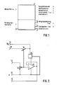
- Fig. 1 the mechanical part 1 of an electrical setpoint device according to the invention and the associated electrical circuit 2 are shown schematically as functional blocks.
- the mechanical part 1 is supplied with the position of the accelerator pedal (neither shown) as a rotation angle via a linkage.
- the output values of mechanical part 1 are returned to the accelerator pedal: the restoring torque, a force hysteresis and a torque peak.
- the output variable which is supplied to other assemblies of the motor vehicle directly, ie without the electronics 2 being interposed, is a signal which is generated by switches dependent on the angle of rotation.
- a signal for identifying the idle position can preferably be generated in the manner described, so that there is additional security against undesired gas application, possibly caused by errors in the electronics.
- the electrical circuit 2 is supplied with a supply voltage, preferably the voltage of the vehicle electrical system.
- the mechanical part 1 acts on a conductive plastic potentiometer.
- the electrical variable thus obtained which is analogous to the position of the accelerator pedal, is fed to an impedance converter in the electrical circuit 2 and is available at the output 3 for forwarding to other assemblies in the motor vehicle, for example an electronic controller.
- the circuit arrangement shown in FIG. 2 represents an exemplary embodiment of the electrical circuit 2 (FIG. 1). While the connection 11 is connected to the ground potential of the motor vehicle, the battery voltage U B is supplied at 12. The conductive plastic potentiometer 13 is connected via the connection 14 to a reference voltage source. An operational amplifier 15 receives its operating voltage via a circuit 16 for voltage stabilization. Suitable components that can be used as operational amplifier 15 and voltage stabilization circuit 16 are commercially available.
- the operational amplifier 15 is connected as an impedance converter by directly coupling its output to the inverting input. For the lowest possible load on the control plate potentiometer 13 the operational amplifier has a small quiescent input current. Since the circuit shown in FIG. 2 is permanently connected to the motor vehicle battery, an operational amplifier 15 is advantageous, the quiescent current of which is also low.
- the selected circuit of the operational amplifier 15 supplies the output 17 with a voltage which corresponds to the voltage set by the potentiometer 13 and which can be supplied to an electronic regulator.
- the grinder 18 of the potentiometer 13 is mechanically connected to a switch 19 which is open in the idle position of the accelerator pedal. As soon as the accelerator pedal is actuated, the switch 19 closes and a voltage corresponding to the battery voltage is present at the output 20, which voltage can then also be supplied to the electronic controller.
- the reference voltage for the potentiometer 13 can also come from the same voltage source as the supply to the operational amplifier 15, for example from the circuit 16.
- the working range of the potentiometer 13 is limited, so that the voltage output by the potentiometer remains below the operating voltage of the operational amplifier 15.
- a voltage-controlled current source can be connected downstream of the operational amplifier 15 or the output stage of the operational amplifier can be designed as a current source. In this case, there is no voltage proportional to the position of the grinder 18 at the output 17, but a current proportional to the position of the grinder 18 is output via the output 17 given. Depending on the design of the connected additional modules, this can be advantageous.
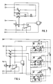
- Fig. 3 shows another embodiment for the circuit 2 (Fig. 1).
- the potentiometer 13, the operational amplifier 15 and the stabilizing circuit 16 are connected as in the circuit arrangement according to FIG. 2.
- the switch 19 FIG. 2
- the fact that the switch 21 is connected via two resistors 24, 25 connected in series, the switch 22 only via the resistor 25 and the switch 23 directly to the connection 26 results in cooperation with an input resistance of a circuit connected to the connection 26 a gradual increase in voltage U k when the accelerator pedal is pressed.
- the circuit of FIG. 3 can be changed such that the switches 21, 22 and 23 are connected to the output 26 via operational amplifiers 27, 28 and 29. Resistors 30, 31 are also connected between the outputs of the operational amplifiers. This circuit has the advantage over the circuit according to FIG. 3 that the contacts of the switches 21, 22 and 23 are loaded with a lower current.
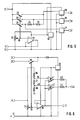
- comparators 27, 28, 29 are used. However, their outputs are independently connected to connections 32, 33, 34. Switching signals are present at these outputs, each of which characterizes an accelerator pedal position given by the coupling of the switches 21, 22, 23 to the grinder 18.
- the potentiometer 13 is connected to the output of the stabilization circuit 16.
- FIG. 6 shows a circuit arrangement in which the accelerator pedal positions in which the voltage U k has a jump are not determined by mechanical measures, but rather by means of measures in the electrical circuit.
- the potentiometer 13, the operational amplifier 15 and the stabilization circuit 16 are connected as in the circuit arrangement according to FIG. 2.
- a voltage divider consisting of three resistors 36, 37, 38 is connected in parallel to the potentiometer 13.
- the taps 39, 40 of the voltage divider are each connected to one of the inputs of two comparators 41, 42.
- the output voltage of the operational amplifier 15 is fed to the other inputs of the comparators 41, 42.
- the outputs of the comparators 41 and 42 are connected via resistors 43, 44 to the connection 45, to which a signal is present which has a jump in each case when the voltage applied to the connection 17 exceeds a threshold given by the resistors 36, 37 and 38 .
- a diode 46 is provided in the circuit arrangement according to FIG. 6 as a reverse polarity protection.
- a switch 19 is also provided in the circuit arrangement according to FIG. 6, with the aid of which a switching signal can be emitted via the output 20 independently of the circuit with the operational amplifiers.
Landscapes
- Engineering & Computer Science (AREA)
- Chemical & Material Sciences (AREA)
- Combustion & Propulsion (AREA)
- Mechanical Engineering (AREA)
- Transportation (AREA)
- General Engineering & Computer Science (AREA)
- Auxiliary Drives, Propulsion Controls, And Safety Devices (AREA)
- Electric Propulsion And Braking For Vehicles (AREA)
- Combined Controls Of Internal Combustion Engines (AREA)
- Measurement Of Length, Angles, Or The Like Using Electric Or Magnetic Means (AREA)
- Control Of Throttle Valves Provided In The Intake System Or In The Exhaust System (AREA)
Applications Claiming Priority (2)
| Application Number | Priority Date | Filing Date | Title |
|---|---|---|---|
| DE19853538232 DE3538232A1 (de) | 1985-10-28 | 1985-10-28 | Elektrischer sollwertgeber |
| DE3538232 | 1985-10-28 |
Publications (2)
| Publication Number | Publication Date |
|---|---|
| EP0226703A2 true EP0226703A2 (fr) | 1987-07-01 |
| EP0226703A3 EP0226703A3 (fr) | 1988-11-09 |
Family
ID=6284609
Family Applications (1)
| Application Number | Title | Priority Date | Filing Date |
|---|---|---|---|
| EP86110586A Ceased EP0226703A3 (fr) | 1985-10-28 | 1986-07-31 | Capteur électrique de niveau de référence |
Country Status (4)
| Country | Link |
|---|---|
| US (1) | US4808935A (fr) |
| EP (1) | EP0226703A3 (fr) |
| JP (1) | JPS62128835A (fr) |
| DE (1) | DE3538232A1 (fr) |
Families Citing this family (2)
| Publication number | Priority date | Publication date | Assignee | Title |
|---|---|---|---|---|
| DE4334963C2 (de) * | 1993-10-13 | 2002-08-22 | Bosch Gmbh Robert | Einrichtung zur Steuerung der Antriebsleistung eines Fahrzeugs bzw. Stellungserfassungsorgan für wenigstens ein Bedienelement in Verbindung mit einer Steuerung der Antriebsleistung eines Fahrzeugs |
| AUPN716895A0 (en) * | 1995-12-15 | 1996-01-18 | Orbital Engine Company (Australia) Proprietary Limited | Throttle position sensors |
Family Cites Families (14)
| Publication number | Priority date | Publication date | Assignee | Title |
|---|---|---|---|---|
| DE2250440A1 (de) * | 1972-10-14 | 1974-04-18 | Bosch Gmbh Robert | Anordnung zum steuern des hauptdrucks in automatischen getriebesteuervorrichtungen |
| JPS5153333A (en) * | 1974-08-02 | 1976-05-11 | Honda Motor Co Ltd | Jidohensokukitsukisharyono gensokujotaikenshutsusochi |
| JPS5952639B2 (ja) * | 1977-06-15 | 1984-12-20 | 株式会社日立製作所 | チヨツパ制御用通流率制御発振回路 |
| US4286386A (en) * | 1977-09-06 | 1981-09-01 | Long Irvin E | Electro-mechanical displacement measuring device |
| DE3044482A1 (de) * | 1980-11-26 | 1982-08-19 | SMS Schloemann-Siemag AG, 4000 Düsseldorf | Schaltungsanordnung zur digitalen anzeige |
| DE3109638A1 (de) * | 1981-03-13 | 1982-09-23 | Vdo Adolf Schindling Ag, 6000 Frankfurt | Schutz- und ueberwachungseinrichtung fuer steuerschaltungsanordnungn in kraftfahrzeugen |
| DE3149361C2 (de) * | 1981-12-12 | 1986-10-30 | Vdo Adolf Schindling Ag, 6000 Frankfurt | Elektrisches Gaspedal |
| JPS5912856A (ja) * | 1982-07-14 | 1984-01-23 | Fujitsu Ltd | インクジエツト記録ヘツド |
| JPS5943471U (ja) * | 1982-09-17 | 1984-03-22 | 外山工業株式会社 | ホ−ス巻取器 |
| JPS5958124A (ja) * | 1982-09-29 | 1984-04-03 | Nissan Motor Co Ltd | アクセルセンサの保安回路 |
| DE3238218A1 (de) * | 1982-10-15 | 1984-04-19 | Vdo Adolf Schindling Ag, 6000 Frankfurt | Einrichtung zum elektrischen steuern der fahrgeschwindigkeit |
| DE3241024A1 (de) * | 1982-11-06 | 1984-05-10 | Robert Bosch Gmbh, 7000 Stuttgart | Verfahren und vorrichtung zur bedarfsabhaengigen ladersteuerung bei brennkraftmaschinen |
| JPS59190441A (ja) * | 1983-04-11 | 1984-10-29 | Nissan Motor Co Ltd | 車両用アクセル制御装置 |
| DE3408002A1 (de) * | 1984-03-03 | 1985-09-12 | Vdo Adolf Schindling Ag, 6000 Frankfurt | Einrichtung zur herabsetzung von fahrzeuglaengsdynamik-instabilitaeten |
-
1985
- 1985-10-28 DE DE19853538232 patent/DE3538232A1/de active Granted
-
1986
- 1986-07-31 EP EP86110586A patent/EP0226703A3/fr not_active Ceased
- 1986-10-27 JP JP61253901A patent/JPS62128835A/ja active Pending
- 1986-10-28 US US06/924,095 patent/US4808935A/en not_active Expired - Fee Related
Also Published As
| Publication number | Publication date |
|---|---|
| JPS62128835A (ja) | 1987-06-11 |
| DE3538232C2 (fr) | 1990-05-23 |
| EP0226703A3 (fr) | 1988-11-09 |
| US4808935A (en) | 1989-02-28 |
| DE3538232A1 (de) | 1987-05-07 |
Similar Documents
| Publication | Publication Date | Title |
|---|---|---|
| EP0026324B1 (fr) | Appareil électromédical à courant de stimulation | |
| DE19744465C1 (de) | Verfahren zur Überwachung eines Stufenschalters | |
| DE19806821A1 (de) | Gerät zur Feststellung einer Störung in einem Magnetventil | |
| DE2613423C3 (de) | Elektronisches Schaltgerät | |
| DE69811950T2 (de) | Elektronische überwachungsschaltung für elektrische spannung | |
| DE2728229A1 (de) | Ueberwachungseinrichtung fuer die ordnungsgemaesse funktion von lampen, insbesondere in kraftfahrzeugen | |
| DE3928160A1 (de) | Verfahren und schaltungsanordnung zur ueberwachung von elektromotorischen stellgliedern | |
| EP0257180B1 (fr) | Dispositif d'actionnement d'un servo-moteur | |
| EP0226703A2 (fr) | Capteur électrique de niveau de référence | |
| DE3643946A1 (de) | Elektrischer sollwertgeber | |
| DE4322472B4 (de) | Schaltungsanordnung zur Überwachung eines Stellungsgebers | |
| EP4288989A1 (fr) | Circuit de détection d'état et commutateur actionnable à distance | |
| EP1032519A1 (fr) | Cablage pour un composant de reglage, et procede de controle de ce cablage de composant de reglage | |
| DE69103488T2 (de) | Steuerungseinrichtung zur Neigung eines Fahrzeugscheinwerfers. | |
| EP0599191A2 (fr) | Circuit de régulation de vitesse d'un moteur | |
| DE68913138T2 (de) | Positionssteuereinrichtung zur Lageregelung eines beweglichen Organs in verschiedene diskrete Stellungen, speziell für die Neigung von Automobilscheinwerfern. | |
| DE3636808A1 (de) | Motor-stellvorrichtung | |
| EP0474085B1 (fr) | Multimètre pour mesurer différentes grandeurs selon le choix | |
| DE3240280A1 (de) | Schutzschaltung fuer analog- und digitalsignale | |
| DE2437919C2 (de) | Elektrischer Fahrantrieb für ein Fahrzeug | |
| DE102023205036B3 (de) | Verfahren zum Erkennen eines seriellen Lichtbogens in einem Stromkreis | |
| DE3632383A1 (de) | Elektrische schaltvorrichtung fuer stromkreise in kraftfahrzeugen | |
| EP0149023A1 (fr) | Circuit d'étage de sortie | |
| DE3246944A1 (de) | Schaltungsanordnung zur ueberwachung einer elektrischen spannung | |
| EP0158995A2 (fr) | Connection de tension |
Legal Events
| Date | Code | Title | Description |
|---|---|---|---|
| PUAI | Public reference made under article 153(3) epc to a published international application that has entered the european phase |
Free format text: ORIGINAL CODE: 0009012 |
|
| AK | Designated contracting states |
Kind code of ref document: A2 Designated state(s): DE FR GB IT SE |
|
| PUAL | Search report despatched |
Free format text: ORIGINAL CODE: 0009013 |
|
| AK | Designated contracting states |
Kind code of ref document: A3 Designated state(s): DE FR GB IT SE |
|
| 17P | Request for examination filed |
Effective date: 19880928 |
|
| 17Q | First examination report despatched |
Effective date: 19900215 |
|
| STAA | Information on the status of an ep patent application or granted ep patent |
Free format text: STATUS: THE APPLICATION HAS BEEN REFUSED |
|
| 18R | Application refused |
Effective date: 19910427 |
|
| RIN1 | Information on inventor provided before grant (corrected) |
Inventor name: UNGERMANN, HEINZ Inventor name: SAUERSCHELL, WOLFGANG Inventor name: HEUMANN, WILFRIED, DR. ING. |