EP0226790B1 - Laser à l'état solide à structure unitaire - Google Patents
Laser à l'état solide à structure unitaire Download PDFInfo
- Publication number
- EP0226790B1 EP0226790B1 EP86115576A EP86115576A EP0226790B1 EP 0226790 B1 EP0226790 B1 EP 0226790B1 EP 86115576 A EP86115576 A EP 86115576A EP 86115576 A EP86115576 A EP 86115576A EP 0226790 B1 EP0226790 B1 EP 0226790B1
- Authority
- EP
- European Patent Office
- Prior art keywords
- laser
- housing
- rod
- laser rod
- lamp
- Prior art date
- Legal status (The legal status is an assumption and is not a legal conclusion. Google has not performed a legal analysis and makes no representation as to the accuracy of the status listed.)
- Expired
Links
Images


Classifications
-
- H—ELECTRICITY
- H01—ELECTRIC ELEMENTS
- H01S—DEVICES USING THE PROCESS OF LIGHT AMPLIFICATION BY STIMULATED EMISSION OF RADIATION [LASER] TO AMPLIFY OR GENERATE LIGHT; DEVICES USING STIMULATED EMISSION OF ELECTROMAGNETIC RADIATION IN WAVE RANGES OTHER THAN OPTICAL
- H01S3/00—Lasers, i.e. devices using stimulated emission of electromagnetic radiation in the infrared, visible or ultraviolet wave range
- H01S3/02—Constructional details
- H01S3/025—Constructional details of solid state lasers, e.g. housings or mountings
-
- H—ELECTRICITY
- H01—ELECTRIC ELEMENTS
- H01S—DEVICES USING THE PROCESS OF LIGHT AMPLIFICATION BY STIMULATED EMISSION OF RADIATION [LASER] TO AMPLIFY OR GENERATE LIGHT; DEVICES USING STIMULATED EMISSION OF ELECTROMAGNETIC RADIATION IN WAVE RANGES OTHER THAN OPTICAL
- H01S3/00—Lasers, i.e. devices using stimulated emission of electromagnetic radiation in the infrared, visible or ultraviolet wave range
- H01S3/02—Constructional details
- H01S3/04—Arrangements for thermal management
- H01S3/042—Arrangements for thermal management for solid state lasers
-
- H—ELECTRICITY
- H01—ELECTRIC ELEMENTS
- H01S—DEVICES USING THE PROCESS OF LIGHT AMPLIFICATION BY STIMULATED EMISSION OF RADIATION [LASER] TO AMPLIFY OR GENERATE LIGHT; DEVICES USING STIMULATED EMISSION OF ELECTROMAGNETIC RADIATION IN WAVE RANGES OTHER THAN OPTICAL
- H01S3/00—Lasers, i.e. devices using stimulated emission of electromagnetic radiation in the infrared, visible or ultraviolet wave range
- H01S3/09—Processes or apparatus for excitation, e.g. pumping
- H01S3/091—Processes or apparatus for excitation, e.g. pumping using optical pumping
- H01S3/0915—Processes or apparatus for excitation, e.g. pumping using optical pumping by incoherent light
- H01S3/092—Processes or apparatus for excitation, e.g. pumping using optical pumping by incoherent light of flash lamp
- H01S3/093—Processes or apparatus for excitation, e.g. pumping using optical pumping by incoherent light of flash lamp focusing or directing the excitation energy into the active medium
-
- H—ELECTRICITY
- H01—ELECTRIC ELEMENTS
- H01S—DEVICES USING THE PROCESS OF LIGHT AMPLIFICATION BY STIMULATED EMISSION OF RADIATION [LASER] TO AMPLIFY OR GENERATE LIGHT; DEVICES USING STIMULATED EMISSION OF ELECTROMAGNETIC RADIATION IN WAVE RANGES OTHER THAN OPTICAL
- H01S3/00—Lasers, i.e. devices using stimulated emission of electromagnetic radiation in the infrared, visible or ultraviolet wave range
- H01S3/02—Constructional details
- H01S3/04—Arrangements for thermal management
- H01S3/0405—Conductive cooling, e.g. by heat sinks or thermo-electric elements
-
- H—ELECTRICITY
- H01—ELECTRIC ELEMENTS
- H01S—DEVICES USING THE PROCESS OF LIGHT AMPLIFICATION BY STIMULATED EMISSION OF RADIATION [LASER] TO AMPLIFY OR GENERATE LIGHT; DEVICES USING STIMULATED EMISSION OF ELECTROMAGNETIC RADIATION IN WAVE RANGES OTHER THAN OPTICAL
- H01S3/00—Lasers, i.e. devices using stimulated emission of electromagnetic radiation in the infrared, visible or ultraviolet wave range
- H01S3/02—Constructional details
- H01S3/04—Arrangements for thermal management
- H01S3/0407—Liquid cooling, e.g. by water
Definitions
- This invention relates to an optically-pumped solid-state laser whose laser medium and pump lamp are both embedded in a transparent solid housing.
- US-A-4 170 763 disclosed a conductively cooled laser pumping assembly in which the laser rod is supported by clamps that connect the ends of the rod to a heat conductive body.
- US-A-4 429 394 disclosed a conduction cooled solid-state laser that has a gap between a laser crystal and pump lamp mounted in a solid housing.
- GB-A-1 181 021 discloses a laser structure in accordance with the prior art portion of claim 1.
- the housing is an integral block of transparent material.
- the present invention as characterised in claim 1, facilitates removal and replacement of the pump lamp and laser rod and reduces thermal stresses.
- the laser medium may have any suitable shape; e.g., rod, slab, etc.
- the medium e.g., rod, slab, etc.
- the laser rod and pump lamp are embedded in the housing, the laser of the present invention is simple, compact and rugged.
- embedded we mean that the rod and lamp are substantially surrounded by the housing on all sides, except possibly for the ends.
- Fig. 1 is a diagramatic illustration in partial cross section of a laser apparatus of the present invention.
- Fig. 2 is a side view of another embodiment of a laser of this invention.
- Fig. 3 is an end-on view, partially cut away, of a cooled laser of this invention.
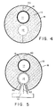
- Fig. 4 is a cross-sectional view of the apparatus of Fig. 1.
- Fig. 5 is a cross-sectional view of another apparatus of the present invention.
- the present invention provides a solid-state laser that has a unitary structure; i.e., the elements of the pump chamber - laser medium, pump lamp, and optical resonator - are a unit.
- the laser is simple, compact, and rugged.
- Fig. 1 depicts a separate envelope structure 11a for lamp 11.
- the pump lamp envelope 11a may have a filter coating 16, to eliminate unwanted spectral components of the lamp output.
- a suitably chosen coating 16 will reflect back into the lamp those wavelengths (infrared and ultraviolet, for example) that do not efficiently excite the laser rod.
- elimination of the ultraviolet component can prevent solarization of the laser rod.
- a bonding agent 17 may surround the pump lamp and/or the laser rod. Greater efficiency can often be achieved by having an optional reflective coating or reflective element 18 around housing 10. Silver, of course, is a good reflecting material.
- Fig. 2 is a side view of an embodiment of the laser that includes radial cooling fins 20 that extend outward from housing 10.
- Fig. 3 in an end-on view, depicts an embodiment in which the cooling provided by fins 20 is augmented by a flow of coolant between the fins 20 and around the outside of housing 10.
- the coolant flow is directed through a shroud 30, which includes a baffle 31 that extends between the fins and deflects the coolant out of the shroud.
- Flowing a cooling fluid, such as air or water, over the outside of the housing places far fewer constraints on the system then does the conventional method of flowing fluid over the laser rod or lamp envelope.
- fluid cools the laser rod or lamp directly, its optical properties are important, and it must be stable despite being subjected to higher temperatures and radiation levels. Extreme cleanliness is essential, and any residue from the fluid can have a strong detrimental effect on laser performance.
- Fig 4 is a sectional view taken along the line 4-4 in Fig 1. It shows circular cross sections for housing 10, pump lamp 11, and laser rod 12. Also shown are filter coating 16 and reflective coating 18. In the embodiment shown, the housing comprises two semi-cylindrical sections joined at surface 40. Such a "clam shell” structure facilitates removal and replacement of the pump lamp and laser rod and reduces thermal stresses.
- Fig 5 is a sectional view of another embodiment of the present invention.
- the diameter of laser rod 12 is slightly smaller than that of its cavity in housing 10, leaving an annular gap 50.
- the laser rod may be supported by support 51, which optionally may include a conventional heater 52.
- the configuration shown in Fig 5, with heater 52, is particularly preferred when it is desired to operate the laser medium - alexandrite, for example - at an elevated temperature.
- the heater permits the user to bring the laser rod to an elevated temperature before lasing is begun, and gap 50 provides insulation to minimize the heat being conducted away by housing 10.
- an alexandrite laser having that structure can provide efficient (i.e., high-temperature) operation from the onset of lasing.
- the laser rod, pump lamp, and housing all heat up.
- laser media like alexandrite and emerald, whose output efficiency are not diminished at elevated temperatures, are preferred.
- high temperature operation would cause excessive stresses to build up if the thermal expansion coefficient of the housing is substantially different from that of the laser rod or pump lamp envelope materials.
- the laser rod and lamp envelope have thermal expansion coefficients similar to that of the housing. The thermal expansion coefficient difference that can be tolerated depends on the temperature at which the element (lamp or laser rod) will operate, the clearance between the element and the cavity wall, and the strength of the element and housing.
- lamp envelope and housing materials An important criterion for the choice of lamp envelope and housing materials is that they transmit in the wavelength region of the laser pump bands.
- materials that are suitable are certain glasses, fused silica, quartz, chrysoberyl, and sapphire.
- Sapphire and fused silica are preferred envelope materials, because they are suitable and are available commercially.
- Sapphire is a preferred housing material because of its superior thermal shock resistance.
- Glass moldings are also suitable for housings.
- the relevant parameters that guide the choice of materials in a particular instance - e.g., transmission spectra, thermal conductivity, and thermal expansion coefficient - are tabulated in reference works such as the American Institute of Physics Handbook, published by McGraw-Hill.
Landscapes
- Physics & Mathematics (AREA)
- Electromagnetism (AREA)
- Engineering & Computer Science (AREA)
- Plasma & Fusion (AREA)
- Optics & Photonics (AREA)
- Lasers (AREA)
Claims (8)
- Laser à structure unitaire comprenant un logement (10) transparent, solide, thermiquement conducteur, une tige laser (12) comportant deux extrémités opposées et encastrée dans une première cavité du logement, une lampe de pompage (11) pour exciter la tige laser qui est encastrée dans une seconde cavité du logement, et des réflecteurs (13, 14) aux extrémités opposées de la tige laser qui définissent une cavité optique résonante et supportent le rayonnement cohérent émis par la tige laser, caractérisé en ce que le logement est constitué de deux sections de corps appariées, réunies au droit d'une surface (40) coupant des évidements ménagés dans les sections du corps qui coopèrent pour former les première et seconde cavités afin de recevoir la lampe de pompage (11) et la tige laser (12) avec une structure du type "coquille de peigne".
- Laser selon la revendication 1, dans lequel le logement est en saphir.
- Laser selon la revendication 1 ou 2, comprenant en outre un revêtement réfléchissant sur la surface extérieure du logement.
- Laser selon l'une quelconque des revendications précédentes, comprenant en outre un moyen pour refroidir l'extérieur du logement.
- Laser selon l'une quelconque des revendications précédentes, dans lequel la tige laser est en alexandrite ou émeraude.
- Laser selon l'une quelconque des revendications précédentes, dans lequel l'enveloppe de la lampe de pompage est en saphir ou en silice obtenue par pyrogénation.
- Laser selon l'une quelconque des revendications précédentes, dans lequel l'enveloppe de la lampe comporte un revêtement filtrant sur sa surface.
- Laser selon l'une quelconque des revendications précédentes, comprenant en outre un moyen de support pour la tige laser, un moyen de chauffage pour la tige laser, et un interstice entre la tige laser et le logement.
Applications Claiming Priority (2)
| Application Number | Priority Date | Filing Date | Title |
|---|---|---|---|
| US809606 | 1985-12-16 | ||
| US06/809,606 US4734913A (en) | 1985-12-16 | 1985-12-16 | Unitary solid-state laser |
Publications (3)
| Publication Number | Publication Date |
|---|---|
| EP0226790A2 EP0226790A2 (fr) | 1987-07-01 |
| EP0226790A3 EP0226790A3 (en) | 1988-03-16 |
| EP0226790B1 true EP0226790B1 (fr) | 1992-06-24 |
Family
ID=25201763
Family Applications (1)
| Application Number | Title | Priority Date | Filing Date |
|---|---|---|---|
| EP86115576A Expired EP0226790B1 (fr) | 1985-12-16 | 1986-11-10 | Laser à l'état solide à structure unitaire |
Country Status (6)
| Country | Link |
|---|---|
| US (2) | US4734913A (fr) |
| EP (1) | EP0226790B1 (fr) |
| JP (1) | JPS62145886A (fr) |
| AU (1) | AU591533B2 (fr) |
| CA (1) | CA1285058C (fr) |
| DE (1) | DE3685808T2 (fr) |
Families Citing this family (21)
| Publication number | Priority date | Publication date | Assignee | Title |
|---|---|---|---|---|
| US4734913A (en) * | 1985-12-16 | 1988-03-29 | Allied Corporation | Unitary solid-state laser |
| US4858242A (en) * | 1988-06-27 | 1989-08-15 | Allied-Signal Inc. | Unitary solid-state laser |
| US4894837A (en) * | 1988-11-18 | 1990-01-16 | Spectra-Physics | Absorbing filter in pump cavity for control of beam quality |
| JPH02186685A (ja) * | 1989-01-13 | 1990-07-20 | Tosoh Corp | 固体レーザー発振装置 |
| US4933946A (en) * | 1989-08-14 | 1990-06-12 | Allied-Signal Inc. | Conductively cooled solid-state slab laser |
| US4949346A (en) * | 1989-08-14 | 1990-08-14 | Allied-Signal Inc. | Conductively cooled, diode-pumped solid-state slab laser |
| JPH0410587A (ja) * | 1990-04-27 | 1992-01-14 | Herutsu Kogyo Kk | 固体レーザ材料の励起方法 |
| DE4022818A1 (de) * | 1990-07-18 | 1992-01-23 | Deutsche Forsch Luft Raumfahrt | Festkoerperlaser |
| DE4303956C2 (de) * | 1993-02-10 | 1995-06-01 | Langner Walter | Laser |
| US5331652A (en) * | 1993-03-22 | 1994-07-19 | Alliedsignal Inc. | Solid state laser having closed cycle gas cooled construction |
| JPH0766473A (ja) * | 1993-08-26 | 1995-03-10 | Matsushita Electric Ind Co Ltd | ガスレーザ発振器 |
| DE4425681A1 (de) * | 1994-07-20 | 1996-01-25 | Patent Treuhand Ges Fuer Elektrische Gluehlampen Mbh | Baueinheit mit einer Lampe |
| DE4425682A1 (de) * | 1994-07-20 | 1996-01-25 | Patent Treuhand Ges Fuer Elektrische Gluehlampen Mbh | Lampe-Reflektoreinheit |
| FR2725315B1 (fr) * | 1994-09-29 | 1996-12-27 | Lokki Sa | Appareil laser a emission pulsee, utilise dans le domaine medical |
| DE69720287T2 (de) * | 1996-08-07 | 2004-01-15 | Lumonics Inc | Laser mit mehreren Elementen und gefaltetem Strahlengang |
| US5867518A (en) * | 1996-08-07 | 1999-02-02 | Lumonics Inc. | Multiple element laser pumping chamber |
| US5867519A (en) * | 1996-08-07 | 1999-02-02 | Lumonics Inc. | Multiple element, folded beam laser |
| JP2001117041A (ja) * | 1999-10-19 | 2001-04-27 | Ricoh Co Ltd | 光走査装置及び画像形成装置 |
| US20040132228A1 (en) * | 2002-12-17 | 2004-07-08 | Honeywell International Inc. | Method and system for fabricating an OLED |
| US20040219390A1 (en) * | 2003-01-23 | 2004-11-04 | Honeywell International, Inc. | Benzoxazinone and quinazolinone derivatives |
| US20100054289A1 (en) * | 2008-08-29 | 2010-03-04 | Cobolt Ab | Solid-state laser |
Family Cites Families (19)
| Publication number | Priority date | Publication date | Assignee | Title |
|---|---|---|---|---|
| US3471801A (en) * | 1964-12-31 | 1969-10-07 | Hughes Aircraft Co | Thermally controlled solid-state laser |
| GB1181021A (en) * | 1966-03-31 | 1970-02-11 | American Optical Corp | Improvements in or relating to laser Structures |
| US3455666A (en) * | 1966-05-06 | 1969-07-15 | American Optical Corp | Method of making laser components |
| US3500238A (en) * | 1967-03-06 | 1970-03-10 | American Optical Corp | Laser assemblies and the like |
| US3528030A (en) * | 1967-08-16 | 1970-09-08 | Honeywell Inc | Laser cavity comprising severable elements respectively carrying the laser rod and pumping source |
| US3676798A (en) * | 1969-10-13 | 1972-07-11 | Sperry Rand Corp | Cooling system for lasing media |
| US3626319A (en) * | 1970-04-14 | 1971-12-07 | Warner Lambert Pharmaceutical | Laser structures and the like |
| GB1334009A (en) * | 1971-05-19 | 1973-10-17 | Gen Electric Co Ltd | Laser devices |
| US3805186A (en) * | 1972-11-29 | 1974-04-16 | American Optical Corp | Unitary glass laser assembly |
| US4096450A (en) * | 1977-04-22 | 1978-06-20 | Hughes Aircraft Company | Conductively cooled flashlamp |
| US4170763A (en) * | 1978-01-03 | 1979-10-09 | Gte Sylvania Incorporated | Conductively cooled laser pumping assembly |
| US4199735A (en) * | 1978-07-03 | 1980-04-22 | Gte Sylvania Incorporated | Optical compensation for thermal lensing in conductively cooled laser rod |
| JPS5543266A (en) * | 1978-09-22 | 1980-03-27 | Chuji Saito | Power generator utilizing thermal difference between solar heat and cool water |
| US4601038A (en) * | 1982-01-18 | 1986-07-15 | Gte Government Systems Corporation | Conduction cooled solid state laser |
| US4429394A (en) * | 1981-11-09 | 1984-01-31 | Gte Products Corporation | Conduction cooled solid state laser |
| US4525842A (en) * | 1984-02-24 | 1985-06-25 | Myers John D | Laser device and method |
| JPS60239077A (ja) * | 1984-05-11 | 1985-11-27 | Toshiba Corp | 固体レ−ザ発振装置 |
| US4637028A (en) * | 1984-08-02 | 1987-01-13 | Hughes Aircraft Company | Conductively cooled laser rod |
| US4734913A (en) * | 1985-12-16 | 1988-03-29 | Allied Corporation | Unitary solid-state laser |
-
1985
- 1985-12-16 US US06/809,606 patent/US4734913A/en not_active Expired - Lifetime
-
1986
- 1986-11-10 EP EP86115576A patent/EP0226790B1/fr not_active Expired
- 1986-11-10 DE DE8686115576T patent/DE3685808T2/de not_active Expired - Lifetime
- 1986-11-17 AU AU65312/86A patent/AU591533B2/en not_active Ceased
- 1986-12-12 CA CA000525127A patent/CA1285058C/fr not_active Expired - Lifetime
- 1986-12-16 JP JP61299813A patent/JPS62145886A/ja active Pending
-
1987
- 1987-06-16 US US07/062,940 patent/US4835786A/en not_active Expired - Lifetime
Also Published As
| Publication number | Publication date |
|---|---|
| US4835786A (en) | 1989-05-30 |
| EP0226790A3 (en) | 1988-03-16 |
| EP0226790A2 (fr) | 1987-07-01 |
| DE3685808T2 (de) | 1992-12-24 |
| US4734913A (en) | 1988-03-29 |
| AU6531286A (en) | 1987-06-18 |
| JPS62145886A (ja) | 1987-06-29 |
| DE3685808D1 (de) | 1992-07-30 |
| CA1285058C (fr) | 1991-06-18 |
| AU591533B2 (en) | 1989-12-07 |
Similar Documents
| Publication | Publication Date | Title |
|---|---|---|
| EP0226790B1 (fr) | Laser à l'état solide à structure unitaire | |
| US4949346A (en) | Conductively cooled, diode-pumped solid-state slab laser | |
| US5619522A (en) | Laser pump cavity | |
| EP0583944B1 (fr) | Cavité réfléchissante laser avec suppression de l'ASE et enlèvement de chaleur | |
| JP7361748B2 (ja) | 安定性の改善されたレーザ駆動封止ビームランプ | |
| US4232276A (en) | Laser apparatus | |
| EP1867012B1 (fr) | Laser a solide a tube a pompage lateral | |
| WO1998032197A1 (fr) | Puits thermique optiquement transparent pour le refroidissement d'un element d'un laser dans le sens de la longueur | |
| US5353293A (en) | Hybrid cooled ion laser | |
| JPS62262480A (ja) | レ−ザ装置 | |
| CA1298644C (fr) | Laser a semiconducteur unitaire | |
| US20120120975A1 (en) | Diode-pumped cavity | |
| US3437950A (en) | Ion laser having a metal tube shrink-fitted onto the ceramic discharge tube | |
| US4752936A (en) | Gas laser, particularly ion laser | |
| US3582822A (en) | Laser flash tube | |
| US6266352B1 (en) | Laser oscillation apparatus | |
| US7382818B2 (en) | Diffusion bonded pump cavity | |
| US5832016A (en) | Slab laser assembly | |
| US4933946A (en) | Conductively cooled solid-state slab laser | |
| US5781573A (en) | High power solid state laser and method of increasing power using same | |
| EP0078941A1 (fr) | Laser à Alexandrite pompé par diode émettrice de lumière | |
| US3764935A (en) | Laser pump enclosure | |
| US5331653A (en) | Solid-state laser device | |
| JP3951782B2 (ja) | 半導体レーザ励起固体レーザ増幅装置、半導体レーザ励起固体レーザ装置、および半導体レーザ励起固体レーザ増幅装置における半導体レーザの冷却方法 | |
| US5682399A (en) | Ion laser tube with a discharge tubule adopted for a high discharge current and a high laser output |
Legal Events
| Date | Code | Title | Description |
|---|---|---|---|
| PUAI | Public reference made under article 153(3) epc to a published international application that has entered the european phase |
Free format text: ORIGINAL CODE: 0009012 |
|
| AK | Designated contracting states |
Kind code of ref document: A2 Designated state(s): DE FR GB NL |
|
| PUAL | Search report despatched |
Free format text: ORIGINAL CODE: 0009013 |
|
| AK | Designated contracting states |
Kind code of ref document: A3 Designated state(s): DE FR GB NL |
|
| 17P | Request for examination filed |
Effective date: 19880614 |
|
| 17Q | First examination report despatched |
Effective date: 19900406 |
|
| RAP1 | Party data changed (applicant data changed or rights of an application transferred) |
Owner name: ALLIED-SIGNAL INC. (A DELAWARE CORPORATION) |
|
| GRAA | (expected) grant |
Free format text: ORIGINAL CODE: 0009210 |
|
| AK | Designated contracting states |
Kind code of ref document: B1 Designated state(s): DE FR GB NL |
|
| REF | Corresponds to: |
Ref document number: 3685808 Country of ref document: DE Date of ref document: 19920730 |
|
| ET | Fr: translation filed | ||
| PLBE | No opposition filed within time limit |
Free format text: ORIGINAL CODE: 0009261 |
|
| STAA | Information on the status of an ep patent application or granted ep patent |
Free format text: STATUS: NO OPPOSITION FILED WITHIN TIME LIMIT |
|
| 26N | No opposition filed | ||
| PGFP | Annual fee paid to national office [announced via postgrant information from national office to epo] |
Ref country code: GB Payment date: 19951009 Year of fee payment: 10 |
|
| PGFP | Annual fee paid to national office [announced via postgrant information from national office to epo] |
Ref country code: FR Payment date: 19951116 Year of fee payment: 10 |
|
| PGFP | Annual fee paid to national office [announced via postgrant information from national office to epo] |
Ref country code: DE Payment date: 19951129 Year of fee payment: 10 |
|
| PGFP | Annual fee paid to national office [announced via postgrant information from national office to epo] |
Ref country code: NL Payment date: 19960924 Year of fee payment: 11 |
|
| PG25 | Lapsed in a contracting state [announced via postgrant information from national office to epo] |
Ref country code: GB Effective date: 19961110 |
|
| GBPC | Gb: european patent ceased through non-payment of renewal fee |
Effective date: 19961110 |
|
| PG25 | Lapsed in a contracting state [announced via postgrant information from national office to epo] |
Ref country code: FR Effective date: 19970731 |
|
| PG25 | Lapsed in a contracting state [announced via postgrant information from national office to epo] |
Ref country code: DE Effective date: 19970801 |
|
| REG | Reference to a national code |
Ref country code: FR Ref legal event code: ST |
|
| PG25 | Lapsed in a contracting state [announced via postgrant information from national office to epo] |
Ref country code: NL Free format text: LAPSE BECAUSE OF NON-PAYMENT OF DUE FEES Effective date: 19980601 |
|
| NLV4 | Nl: lapsed or anulled due to non-payment of the annual fee |
Effective date: 19980601 |