EP0226852A2 - Appareil de commande du rapport air/carburant pour un moteur à combustion - Google Patents
Appareil de commande du rapport air/carburant pour un moteur à combustion Download PDFInfo
- Publication number
- EP0226852A2 EP0226852A2 EP86116358A EP86116358A EP0226852A2 EP 0226852 A2 EP0226852 A2 EP 0226852A2 EP 86116358 A EP86116358 A EP 86116358A EP 86116358 A EP86116358 A EP 86116358A EP 0226852 A2 EP0226852 A2 EP 0226852A2
- Authority
- EP
- European Patent Office
- Prior art keywords
- fuel ratio
- air
- engine
- speed
- speed reduction
- Prior art date
- Legal status (The legal status is an assumption and is not a legal conclusion. Google has not performed a legal analysis and makes no representation as to the accuracy of the status listed.)
- Granted
Links
Images


Classifications
-
- F—MECHANICAL ENGINEERING; LIGHTING; HEATING; WEAPONS; BLASTING
- F02—COMBUSTION ENGINES; HOT-GAS OR COMBUSTION-PRODUCT ENGINE PLANTS
- F02D—CONTROLLING COMBUSTION ENGINES
- F02D41/00—Electrical control of supply of combustible mixture or its constituents
- F02D41/02—Circuit arrangements for generating control signals
- F02D41/14—Introducing closed-loop corrections
- F02D41/1438—Introducing closed-loop corrections using means for determining characteristics of the combustion gases; Sensors therefor
- F02D41/1486—Introducing closed-loop corrections using means for determining characteristics of the combustion gases; Sensors therefor with correction for particular operating conditions
-
- F—MECHANICAL ENGINEERING; LIGHTING; HEATING; WEAPONS; BLASTING
- F02—COMBUSTION ENGINES; HOT-GAS OR COMBUSTION-PRODUCT ENGINE PLANTS
- F02D—CONTROLLING COMBUSTION ENGINES
- F02D41/00—Electrical control of supply of combustible mixture or its constituents
- F02D41/02—Circuit arrangements for generating control signals
- F02D41/021—Introducing corrections for particular conditions exterior to the engine
- F02D41/0215—Introducing corrections for particular conditions exterior to the engine in relation with elements of the transmission
- F02D41/0225—Introducing corrections for particular conditions exterior to the engine in relation with elements of the transmission in relation with the gear ratio or shift lever position
Definitions
- the present invention relates to an apparatus for controlling an air-fuel ratio for an internal combustion engine. More particularly, the present invention pertains to an apparatus for controlling an air-fuel ratio for an internal combustion engine such that the air-fuel ratio coincides with a stoichiometric air-fuel ratio, and when the engine is under a predetermined operating condition, the air-fuel ratio is maintained at the leaner side of the stoichiometric air-fuel ratio.
- one type of air-fuel ratio feedback control has heretofore been practiced in which a basic fuel injection quantity is determined on the basis of an engine load (e.g., an intake-air quantity per revolution of an engine or an intake-pipe pressure) and a rotational speed of the engine, and this basic fuel injection quantity is corrected in accordacne with the output of an 0 2 sensor which detectes the residual oxygen concentration in the exhaust gas.
- a partial-lean control is effected for the purpose of decreasing the rate of fuel consumption and of reducing the amounts of H C and CO in the exhaust gas.
- the feedback control is suspended and switched to a partial-lean control in which the air-fuel ratio is maintained at the leaner side of the stoichiometric level through an open loop control.
- the leanest value for the air-fuel ratio is set in the vicinity of a misfire region in which misfire may occur and which is determined by both the engine load Q/N and the engine rotational speed N as shown in the specification of Japanese Patent Laid-Open No. 211543/1983.
- critical air-fuel ratio concerning the misfire region
- the air-fuel ratio can be controlled so as to be increasingly leaner as the engine load and the engine speed increase.
- the vibration of a vehicle caused by surges of the engine output overlaps a vibration frequency band to which man is most sensitive when the rotational speed as an output of a transmission is small relative to the rotational speed of the engine (i.e., when the speed reduction ratio is large). Accordingly, when the leanest value in the partial-lean control is set in the vicinity of the misfire region as in the conventional practice, unpleasant surges may be generated due to changes in combustion state particularly when the vehicle is running in the 1st speed gear position, causing driveability to be deteriorated. To overcome this problem, it may be taken into consideration to set the leanest value in the partial-lean control so as to be richer than the critical misfire air-fuel ratio on the basis of the 1st speed gear position.
- the air-fuel ratio is controlled such as to be richer than the critical misfire air-fuel ratio even when the transmission is set in an intermediate speed gear position or in the top speed gear position where the driveability is not deteriorated by the occurrence of surges because the surge frequency is sufficiently high, resulting disadvantageously in an increase in the rate of fuel consumption.
- the present invention provides an apparatus for controlling an air-fuel ratio for an internal combustion engine, comprising: calculating means for calculating a basic fuel injection quantity on the basis of an engine load and a rotational speed of the engine; operating condition detecting means for detecting an operating condition of the engine; speed reduction ratio detecting means for detecting a speed reduction ratio set in a transmission; and control means which controls, when a predetermined operating condition is detected, the air-fuel ratio so as to be leaner than a stoichiometric air-fuel ratio on the basis of the basic fuel injection quantity in such a manner that the degree by which the air-fuel ratio is made leaner than the stoichiometric air-fuel ratio is greater when the speed reduction ratio is relatively small than that in the case where the speed reduction ratio is relatively large.
- the control means may include fuel injection quantity calculating means for calculating a fuel injection quantity on the basis of a basic fuel injection quantity, an engine operating condition and a speed reduction ratio, and fuel injection means for injecting fuel on the basis of the output of the fuel injection quantity calculating means.
- a basic fuel injection quantity is calculated by the calculating means on the basis of an engine load and a rotational speed of the engine, and when a predetermined operating condiction, e.g., a normal operating condition, is detected by the operating condition detecting means, the air-fuel ratio is controlled so as to be at the leaner side of a stoichiometric air-fuel ratio by the control means on the basis of the basic fuel injection quantity.
- a predetermined operating condiction e.g., a normal operating condition
- control means controls the air-fuel ratio on the basis of the speed reduction ratio detected by the speed reduction ratio detecting means in such a manner that the degree by which the air-fuel ratio is made leaner than the stoichiometric air-fuel ratio is greater when the speed reduction ratio is relatively small than that in the case where the speed reduction ratio is relatively large.
- the air-fuel ratio is controlled so as to be richer that the critical misfire air-fuel ratio, thereby preventing occurrence of surges in the engine output which would otherwise be caused by changes in combustion state, whereas, when the speed reduction ratio is relatively small, the air-fuel ratio is made to approach the critical misfire air-fuel ratio, thereby allowing the rate of fuel consumption to be minimized.
- surges of the engine output may be generated since the air-fuel ratio is controlled so as to be in the vicinity of the misfire region.
- the frequency of the surges in this case is sufficiently high, the driver feels no unpleasantness and there is therefore no adverse effect on the driveability.
- the air-fuel ratio is controlled so that the degree by which the air-fuel ratio is made richer than a stoichiometric air-fuel ratio is greater when the speed reduction ratio is relatively large than that in the case where the speed reduction ratio is relatively small. It is therefore possible to minimize the rate of fuel consumption without any fear of driveability being degraded by possible surges of the engine output.
- the air-fuel ratio is controlled so that the degree by which the air-fuel ratio is made leaner than the stoichiometric air-fuel ratio is greater than that in the case where the speed reduction ratio is relatively large. Accordingly, it is advantageously possible to reduce the amount of entire NO X in the exhaust gas over all the operating conditions of the engine.
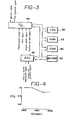
- Fig. 2 schematically shows an internal combustion engine (hereinafter referred to as an "engine") equipped with a manual transmission to which one embodiment of the air-fuel ratio control apparatus according to the present invention is applied.
- engine an internal combustion engine
- An air flowmeter 2 is disposed on the downstream side of an air cleaner (not shown).
- the air flowmeter 2 consists of a compensation plate 2A pivotally provided within a damping chamber, a measuring plate 2B adapted to pivot in response to the movement of the compensation plate 2A, and a potentiometer 2C adapted to convert the pivotal movement of the measuring plate 2B into a voltage.
- a throttle valve 4 is disposed on the downstream side of the air flowmeter 2.
- An idle switch 6 is secured to the shaft of the throttle valve 4.
- the switch 6 is actuated in response to the movement of the throttle valve 4 in such a manner that, when the valve 4 is in the full-closing position (during idling), the switch 6 is turned on, whereas, when the valve 4 is in an open position, the switch 6 is turned off.
- a throttle full-open switch 26 is secured to the shaft of the throttle valve 4 in such a manner that the switch 26 is turned on when the valve 4 is in the full-open position (during full-load operation).
- a surge tank 8 is disposed on the downstream side of the throttle valve 4, and communicated with a combustion chamber 12 of the engine through an intake manifold 10.
- a fuel injection valve 14 is provided on the intake manifold 10 for each cylinder of the engine.
- the combustion chamber 12 of the engine is communicated through an exhaust manifold 16 with a catalyst device 18 which is filled with a ternary catalyst.
- a cooling water temperature sensor 20 is mounted on the engine block, the sensor 20 being adapted to detect the temperature of water for cooling the engine and output a cooling water temperature signal.
- the distal end of an ignition plug 22 extends into the combustion chamber of the engine.
- a distributor 24 is connected to the ignition plug 22.
- the distributor 24 is provided with an engine speed sensor 28 which is constituted by a pickup rigidly secured to the distributor housing and a signal rotor rigidly secured to the shaft of the distributor 24.
- the engine speed sensor 28 outputs an engine speed signal which is raised to a high level, e.g., every crank angle of 30° to a control circuit 30 which is constituted by a microcomputer or other similar means.
- the distributor 24 is connected to an ignitor 32,.
- the reference numeral 34 in Fig. 2 denotes a vehicle speed sensor which is constituted by a magnet rigidly secured to a speedometer cable rotated by the output shaft of a transmission, and a magnetic sensitive element.
- the control circuit 30 includes a central processing unit (CPU) 36, a read-only memory (ROM) 38, a random-access memory (RAM) 40, a backup RAM (BU-RAM) 42, an input/output port (I/O) 44, an analog-to-digital converter (ADC) 46, and buses for interconnecting these elements, such as a data bus and a control bus.
- CPU central processing unit
- ROM read-only memory
- RAM random-access memory
- BU-RAM backup RAM
- I/O input/output port
- ADC analog-to-digital converter
- the ADC 46 is supplied with, as its inputs, an intake-air quantity signal from the air flowmeter 2 and a cooling water temperature signal from the cooling water temperature sensor 20, and the ADC 46 converts these signals into digital signals, respectively.
- the ROM 38 has stored therein in advance a map of basic fuel injection quantity TAU O which is determined on the basis of both the rotational speed NE of the engine and the intake-air quantity Q/N per revolution of the engine and with which a particular air-fuel ratio coincides with a stoichiometric air-fuel ratio, a map of partial-lean correction coefficients determined in correspondence with various rotational speeds NE of the engine as shown in Fig. 4, and programs for routines described below.
- the air-fuel ratio is controlled so as to coincide with a stoichiometric air-fuel ratio through an open loop control, and the air-fuel ratio is controlled in accordance with a speed reduction ratio under a predetermined operating condition of the engine.
- a judgement is made as to whether or not conditions for partial-lean control are met in Steps 100 to 104. More specifically, it is judged whether or not partial-lean control conditions are satisfied by making various judgements: a judgement as to whether or not the idle switch 6 is ON; a judgement as to whether or not the throttle full-open switch 26 is ON; and a judgement as to whether or not the engine cooling water temperature THW is less than a predetermined value (e.g., 80 0 C). When the answers to all the questions are NO, the partial-lean control conditions are judged to be met. When the partial-lean control conditions are not satisfied, the process proceeds to Step 126, where the partial-lean quantity FPL is set at 1 (0%).
- Step 106 the vehicle speed V and the engine speed NE are read in Step 106, and a speed reduction ratio, that is, the shift position of the shift lever, is detected in Steps 108 to 122.
- a speed reduction ratio graph is drawn by plotting the vehicle speed V along the axis of abscissas and the engine speed NE along the axis of ordinates, NE/V measured when the shift lever is in any one of the shift positions for forward speeds is constant, and NE/V is relatively large when the shift lever is in a relatively low speed gear position, while NE/V is relatively small in a relatively high speed gear position.
- VK 1 to VK 4 are respectively obtained in Steps 108, 112, 116 and 120, and size comparisons between VK 1 to VK 4 and NE are respectively made in Steps 110, 114, 118 and 122, thereby detecting a speed reduction ratio.
- the partial-lean correction coefficient FPL is set at 1 in Step 126, whereas, when a speed reduction ratio which corresponds to any one of the 2nd to 5th speed gear positions is detected, a partial-lean correction coefficient FPL which corresponds to a present engine speed NE is calculated on the basis of the map shown in Fig. 4 in Step 124.
- Fig. 6 shows a fuel injection quantity calculating routine which is executed as an interruption routine every predetermined crank angle (e.g., every 720 0 ).
- a basic fuel injection quantity TAU O is calculated by interpolation from the map stored in the ROM 38 on the basis of both the intake-air quantity Q/N per revolution of the engine and the engine speed NE in Step 128.
- the calculated basic fuel injection quantity TAU O is multiplied by the partial-lean correction coefficient FPL obtained as described above in Step 130 so as to decrement the basic fuel injection quantity TAU O by a rate corresponding to the partial-lean correction coefficient FPL, thereby obtaining an actual fuel injection quantity TAU, and the process then returns.
- the air-fuel ratio is controlled so as to be at the leaner side of the stoichiometric air-fuel ratio, and when a speed reduction ratio which corresponds to the lst speed gear position is detected, an amount of fuel which corresponds to a basic fuel injection quantity TAU O is injected so that the air-fuel ratio coincides with the stoichiometric air-fuel ratio. Accordingly, the air-fuel ratio is controlled so as to be richer in the lst speed gear position than those in the 2nd to 5th speed gear positions.
- the critical misfire air-fuel ratio becomes leaner as the engine speed increases; therefore, in this embodiment the partial-lean correction coefficient FPL for each of the 2nd to 5th speed gear positions is decreased as the engine speed increases, as shown in Fig. 4. Consequently, the air-fuel ratio is controlled so as to approach the critical misfire air-fuel ratio as the engine speed increases. Since the critical misfire air-fuel ratio becomes leaner as the engine load increases, the partial-lean correction coefficient FPL shown in Fig. 4 may be determined on the basis of the intake-air quantity Q/N per revolution of the engine.
- This embodiment is arranged such that, when a speed reduction ratio which corresponds to the 1st speed gear position is detected, the partial-lean correction coefficient FPL is set at 1 in a manner similar to that in the first embodiment so as to control the air-fuel ratio to a stoichiometric air-fuel ratio, whereas, when a speed reduction ratio which corresponds to any one of the 2nd to 5th speed gear positions is detected, a partial-lean correction coefficient FPL is calculated from the map shown in Fig. 7 to control the air-fuel ratio so as to be leaner than the stoichiometric air-fuel ratio.
- the partial-lean correction coefficient FPL the following various values may be employed in accordance with the shift lever position: a value of the curve C 1 in the 5th speed gear position; a value of the curve C 2 in the 4th speed gear position; a value of the curve C 3 in the 3rd speed gear position; and a value of the curve C 4 in the 2nd speed gear position.
- the values of the curves C 1 to C 4 are set so that, when the engine speed is within a range from 1000 to 1300 (rpm), the values are 1, whereas, when the engine speed is within a range from 1300 to 2000 (rpm), the values decrease as the engine speed increases, and the condition of C 4 >C 3 >C 2 >C 1 is met.
- the air-fuel ratio is controlled so that, as the speed reduction ratio decreases, the air-fuel ratio becomes leaner, and as the engine speed increases, the air-fuel ratio approaches the critical misfire air-fuel ratio.
- the partial-lean correction coefficient FPL shown in Fig. 7 may be determined on the basis of the intake-air quantity per revolution of the engine, or may be set at a constant value which is independent of the engine speed and the intake-air quantity per revolution of the engine (the value, however, decreasing as the speed reduction ratio decreases).
- the present invention has been described by way of one type of engine in which a basic fuel injection quantity is determined on the basis of both the engine speed and the intake-air quantity per revolution of the engine, the present invention is not necessarily limitative thereto and may also be applid to other types of engine, for example, engines in which a basic fuel injection quantity is determined on the basis of both the intake-pipe pressure and the engine speed, engines equipped with automatic transmissions, and engines equipped with transmissions having a number of different speed gear positions which is less than 5.
- the partial-lean correction quantity may be obtained in terms of a rate so that the basic fuel injection quantity is decremented using this rate.
- the air-fuel ratio is controlled so as to coincide with a stoichiometric air-fuel ratio by an open loop control
- the present invention may also be applied to one type of engine in which an 0 2 sensor for detecting the residual oxygen concentration in exhaust gas is mounted on the exhaust manifold, and the air-fuel ratio is feedback-controlled to a stoichiometric air-fuel ratio on the basis of the output of the 0 2 sensor.
- the air-fuel ratio is controlled to a stoichiometric air-fuel ratio.
- the air-fuel ratio may be controlled so as to be leaner than the stoichiometric air-fuel ratio even in the 1st speed gear position by setting the maximum values in the maps shown in Figs. 4 and 7 such as to be less than 1 (e.g., 0.98).
Landscapes
- Engineering & Computer Science (AREA)
- Chemical & Material Sciences (AREA)
- Combustion & Propulsion (AREA)
- Mechanical Engineering (AREA)
- General Engineering & Computer Science (AREA)
- Electrical Control Of Air Or Fuel Supplied To Internal-Combustion Engine (AREA)
Applications Claiming Priority (2)
| Application Number | Priority Date | Filing Date | Title |
|---|---|---|---|
| JP60286388A JPS62147033A (ja) | 1985-12-19 | 1985-12-19 | 内燃機関の空燃比制御装置 |
| JP286388/85 | 1985-12-19 |
Publications (3)
| Publication Number | Publication Date |
|---|---|
| EP0226852A2 true EP0226852A2 (fr) | 1987-07-01 |
| EP0226852A3 EP0226852A3 (en) | 1988-03-02 |
| EP0226852B1 EP0226852B1 (fr) | 1991-01-30 |
Family
ID=17703750
Family Applications (1)
| Application Number | Title | Priority Date | Filing Date |
|---|---|---|---|
| EP86116358A Expired - Lifetime EP0226852B1 (fr) | 1985-12-19 | 1986-11-25 | Appareil de commande du rapport air/carburant pour un moteur à combustion |
Country Status (4)
| Country | Link |
|---|---|
| US (1) | US4732130A (fr) |
| EP (1) | EP0226852B1 (fr) |
| JP (1) | JPS62147033A (fr) |
| DE (1) | DE3677354D1 (fr) |
Cited By (1)
| Publication number | Priority date | Publication date | Assignee | Title |
|---|---|---|---|---|
| DE4139490A1 (de) * | 1991-06-27 | 1993-01-07 | Samsung Electronics Co Ltd | Bicmos-vorrichtung und verfahren zur herstellung derselben |
Families Citing this family (12)
| Publication number | Priority date | Publication date | Assignee | Title |
|---|---|---|---|---|
| US4939956A (en) * | 1987-08-10 | 1990-07-10 | Nissan Motor Company Limited | System for controlling servo activating hydraulic pressure occurring in vehicular power train |
| US4976240A (en) * | 1989-10-18 | 1990-12-11 | Mitsubishi Denki Kabushiki Kaisha | Engine ignition system |
| DE69117370T2 (de) * | 1990-07-16 | 1996-07-25 | Toyota Motor Co Ltd | Steuersystem für Antriebseinheiten und Automatik-Getriebe |
| JPH04124439A (ja) * | 1990-09-14 | 1992-04-24 | Honda Motor Co Ltd | 内燃エンジンの空燃比制御方法 |
| JP2759907B2 (ja) * | 1990-09-17 | 1998-05-28 | 本田技研工業株式会社 | 内燃エンジンの空燃比制御方法 |
| US5643133A (en) * | 1991-02-25 | 1997-07-01 | Hitachi, Ltd. | Change gear control device using acceleration and gear ratio as parameters for automatic transmission in a motor vehicle and the method therefor |
| US5443594A (en) * | 1992-05-27 | 1995-08-22 | Toyota Jidosha Kabushiki Kaisha | Air-fuel ratio control apparatus of vehicle equipped with automatic transmission |
| GB2325754A (en) * | 1997-05-30 | 1998-12-02 | Ford Motor Co | Controlling operating parameter of vehicle driven by IC engine |
| DE19852600A1 (de) * | 1998-11-14 | 2000-05-18 | Bosch Gmbh Robert | Verfahren zum Betreiben einer Brennkraftmaschine insbesondere eines Kraftfahrzeugs |
| JP4477249B2 (ja) * | 2001-02-07 | 2010-06-09 | 本田技研工業株式会社 | 筒内噴射型内燃機関の制御装置 |
| US7072757B2 (en) * | 2001-10-29 | 2006-07-04 | Caterpillar Inc. | Fuel control system |
| WO2003078813A1 (fr) * | 2002-03-20 | 2003-09-25 | Ebara Corporation | Dispositif a turbine a gaz |
Family Cites Families (11)
| Publication number | Priority date | Publication date | Assignee | Title |
|---|---|---|---|---|
| JPS534122A (en) * | 1976-06-29 | 1978-01-14 | Nippon Denso Co Ltd | Air fuel ratio controller for internal combustion engine |
| DE2642738C2 (de) * | 1976-09-23 | 1986-08-07 | Robert Bosch Gmbh, 7000 Stuttgart | Verfahren zur Regelung des Betriebsverhaltens einer Brennkraftmaschine in einem vorgegebenen Betriebsbereich |
| JPS5369625U (fr) * | 1976-11-15 | 1978-06-12 | ||
| US4301779A (en) * | 1979-02-21 | 1981-11-24 | Teledyne Industries, Inc. | Engine fuel mixture control system |
| US4245604A (en) * | 1979-06-27 | 1981-01-20 | General Motors Corporation | Neutral to drive transient enrichment for an engine fuel supply system |
| JPS56135730A (en) * | 1980-03-27 | 1981-10-23 | Nissan Motor Co Ltd | Controlling device for rotational number of internal combustion engine |
| JPS58140471A (ja) * | 1982-02-15 | 1983-08-20 | Toyota Motor Corp | 内燃機関の点火時期制御装置 |
| JPS58211543A (ja) * | 1982-06-02 | 1983-12-09 | Toyota Motor Corp | 内燃機関の空燃比制御方式 |
| JPS5934440A (ja) * | 1982-08-19 | 1984-02-24 | Honda Motor Co Ltd | 車輌用内燃エンジンの混合気の空燃比制御方法 |
| JPS59194053A (ja) * | 1983-04-18 | 1984-11-02 | Toyota Motor Corp | 内燃機関の空燃比制御方法および空燃比制御装置 |
| JPH0713493B2 (ja) * | 1983-08-24 | 1995-02-15 | 株式会社日立製作所 | 内燃機関の空燃比制御装置 |
-
1985
- 1985-12-19 JP JP60286388A patent/JPS62147033A/ja active Pending
-
1986
- 1986-11-17 US US06/931,621 patent/US4732130A/en not_active Expired - Fee Related
- 1986-11-25 EP EP86116358A patent/EP0226852B1/fr not_active Expired - Lifetime
- 1986-11-25 DE DE8686116358T patent/DE3677354D1/de not_active Expired - Lifetime
Cited By (1)
| Publication number | Priority date | Publication date | Assignee | Title |
|---|---|---|---|---|
| DE4139490A1 (de) * | 1991-06-27 | 1993-01-07 | Samsung Electronics Co Ltd | Bicmos-vorrichtung und verfahren zur herstellung derselben |
Also Published As
| Publication number | Publication date |
|---|---|
| EP0226852B1 (fr) | 1991-01-30 |
| DE3677354D1 (de) | 1991-03-07 |
| US4732130A (en) | 1988-03-22 |
| JPS62147033A (ja) | 1987-07-01 |
| EP0226852A3 (en) | 1988-03-02 |
Similar Documents
| Publication | Publication Date | Title |
|---|---|---|
| US4391253A (en) | Electronically controlling, fuel injection method | |
| US5857445A (en) | Engine control device | |
| EP0226852B1 (fr) | Appareil de commande du rapport air/carburant pour un moteur à combustion | |
| JPS60240840A (ja) | 内燃機関の空燃比制御装置 | |
| US5507265A (en) | Compensation method and apparatus for fuel injection amount during engine warm-up | |
| US5701867A (en) | Apparatus for controlling the speed of an engine | |
| US4461261A (en) | Closed loop air/fuel ratio control using learning data each arranged not to exceed a predetermined value | |
| US4487190A (en) | Electronic fuel injecting method and device for internal combustion engine | |
| US4512318A (en) | Internal combustion engine with fuel injection system | |
| US4753208A (en) | Method for controlling air/fuel ratio of fuel supply system for an internal combustion engine | |
| US5661974A (en) | Control system with function of protecting catalytic converter for internal combustion engines for vehicles | |
| JPH02245441A (ja) | 内燃機関 | |
| JP2889419B2 (ja) | 空燃比学習制御方法 | |
| KR900001299B1 (ko) | 엔진 제어장치 | |
| US4646699A (en) | Method for controlling air/fuel ratio of fuel supply for an internal combustion engine | |
| JP2976563B2 (ja) | 内燃機関の空燃比制御装置 | |
| JPS6231180B2 (fr) | ||
| JPH057546B2 (fr) | ||
| JP3002370B2 (ja) | 内燃機関におけるパワー増量補正方法 | |
| JP4186517B2 (ja) | 内燃機関用エアクリーナの目詰まり検出装置 | |
| US6205977B1 (en) | Fuel injection control apparatus of multicylinder internal combustion engine | |
| JP2520608B2 (ja) | 内燃機関の電子制御燃料噴射装置 | |
| JPH0868347A (ja) | 燃料噴射制御方法 | |
| JPH0734926A (ja) | 燃料制御方法 | |
| JPH08312410A (ja) | 内燃機関の空燃比制御方法 |
Legal Events
| Date | Code | Title | Description |
|---|---|---|---|
| PUAI | Public reference made under article 153(3) epc to a published international application that has entered the european phase |
Free format text: ORIGINAL CODE: 0009012 |
|
| AK | Designated contracting states |
Kind code of ref document: A2 Designated state(s): DE FR GB |
|
| PUAL | Search report despatched |
Free format text: ORIGINAL CODE: 0009013 |
|
| AK | Designated contracting states |
Kind code of ref document: A3 Designated state(s): DE FR GB |
|
| 17P | Request for examination filed |
Effective date: 19880429 |
|
| 17Q | First examination report despatched |
Effective date: 19890118 |
|
| GRAA | (expected) grant |
Free format text: ORIGINAL CODE: 0009210 |
|
| AK | Designated contracting states |
Kind code of ref document: B1 Designated state(s): DE FR GB |
|
| ET | Fr: translation filed | ||
| REF | Corresponds to: |
Ref document number: 3677354 Country of ref document: DE Date of ref document: 19910307 |
|
| PLBE | No opposition filed within time limit |
Free format text: ORIGINAL CODE: 0009261 |
|
| STAA | Information on the status of an ep patent application or granted ep patent |
Free format text: STATUS: NO OPPOSITION FILED WITHIN TIME LIMIT |
|
| 26N | No opposition filed | ||
| PGFP | Annual fee paid to national office [announced via postgrant information from national office to epo] |
Ref country code: FR Payment date: 19991109 Year of fee payment: 14 |
|
| PGFP | Annual fee paid to national office [announced via postgrant information from national office to epo] |
Ref country code: GB Payment date: 19991124 Year of fee payment: 14 |
|
| PGFP | Annual fee paid to national office [announced via postgrant information from national office to epo] |
Ref country code: DE Payment date: 19991129 Year of fee payment: 14 |
|
| PG25 | Lapsed in a contracting state [announced via postgrant information from national office to epo] |
Ref country code: GB Free format text: LAPSE BECAUSE OF NON-PAYMENT OF DUE FEES Effective date: 20001125 |
|
| GBPC | Gb: european patent ceased through non-payment of renewal fee |
Effective date: 20001125 |
|
| PG25 | Lapsed in a contracting state [announced via postgrant information from national office to epo] |
Ref country code: FR Free format text: LAPSE BECAUSE OF NON-PAYMENT OF DUE FEES Effective date: 20010731 |
|
| PG25 | Lapsed in a contracting state [announced via postgrant information from national office to epo] |
Ref country code: DE Free format text: LAPSE BECAUSE OF NON-PAYMENT OF DUE FEES Effective date: 20010801 |
|
| REG | Reference to a national code |
Ref country code: FR Ref legal event code: ST |