EP0227016A2 - Dispositif de barrage pour barrer temporairement une chaussée - Google Patents
Dispositif de barrage pour barrer temporairement une chaussée Download PDFInfo
- Publication number
- EP0227016A2 EP0227016A2 EP86117525A EP86117525A EP0227016A2 EP 0227016 A2 EP0227016 A2 EP 0227016A2 EP 86117525 A EP86117525 A EP 86117525A EP 86117525 A EP86117525 A EP 86117525A EP 0227016 A2 EP0227016 A2 EP 0227016A2
- Authority
- EP
- European Patent Office
- Prior art keywords
- locking
- elements
- locking device
- roadway
- blocking
- Prior art date
- Legal status (The legal status is an assumption and is not a legal conclusion. Google has not performed a legal analysis and makes no representation as to the accuracy of the status listed.)
- Granted
Links
Images




Classifications
-
- E—FIXED CONSTRUCTIONS
- E01—CONSTRUCTION OF ROADS, RAILWAYS, OR BRIDGES
- E01F—ADDITIONAL WORK, SUCH AS EQUIPPING ROADS OR THE CONSTRUCTION OF PLATFORMS, HELICOPTER LANDING STAGES, SIGNS, SNOW FENCES, OR THE LIKE
- E01F13/00—Arrangements for obstructing or restricting traffic, e.g. gates, barricades ; Preventing passage of vehicles of selected category or dimensions
- E01F13/04—Arrangements for obstructing or restricting traffic, e.g. gates, barricades ; Preventing passage of vehicles of selected category or dimensions movable to allow or prevent passage
- E01F13/08—Arrangements for obstructing or restricting traffic, e.g. gates, barricades ; Preventing passage of vehicles of selected category or dimensions movable to allow or prevent passage by swinging into closed position about a transverse axis situated in the road surface, e.g. tiltable sections of the road surface, tiltable parking posts
Definitions
- the invention relates to a locking device for temporary locking of a roadway or the like comprising locking elements which are either aligned or pivotable out of alignment with the roadway surface, each locking element being pivotable about an axis running essentially parallel to the main direction of the roadway and having an underneath or is essentially connected below the road surface existing counter element, the elements being pivotable via linkages such as push rods.
- Corresponding passage barriers for the temporary blocking of free lanes can include prism-shaped obstacles that extend along the width of the lane and can be swung out of the lane in order to protect systems such as B. to protect public and private supply centers or power plants against unauthorized or violent intrusion of motor vehicles or bicycles.
- Such obstacles which can also be referred to as locking segments, are quite voluminous, maintenance-intensive and, in principle, no longer function properly when a vehicle is intercepted, ie, the locking element is no longer submersible in the road. In this way, however, the area to be secured is blocked in any case in the event of a disaster.
- An object of the present invention is to design a locking device of the type mentioned in such a way that, with small dimensions of the individual locking elements, it is ensured that unauthorized driving on a roadway - regardless of which side - can be prevented, with regard to the construction and associated with it ease of use, high reliability and ease of maintenance should be guaranteed.
- a further object of the invention is that essentially only the vehicle intercepted by the locking device is rendered inoperable by the locking elements without the persons driving the vehicle being in mortal danger.
- the elements are posts which overlap and lie one above the other in an essentially aligned alignment with the road surface above the axis.
- the pivot axis preferably runs in the counter element, and preferably in the region of the center of gravity of the element and counter element, so that small forces are required to enable pivoting.
- a linkage which can be actuated by a drive element such as a hydraulic cylinder and which is preferably articulated in the area of the counter elements.
- the control of the hydraulic cylinder is designed so that an energy store ensures actuation of the locking elements even when the power fails, since only z. B. a 24 volt battery is required.
- a hand pump can also be provided in order to lower the locking elements in an emergency, ie to pivot the axis running parallel to the longitudinal direction of the carriageway.
- the sections of the blocking elements lying one on top of the other, that is to say of the overlapping regions, are formed by complementarily complementary recesses in the mullion elements assigned to one another, the recesses themselves preferably being stepped.
- the locking elements themselves and preferably also the counter elements consist of double T-beams with an edge length of e.g. 300 mm, at least the flanges of the locking elements being connected with flat bars and having reinforcing ribs between them and the webs.
- the height of the posts projecting above the roadway is preferably 650 mm, which ensures that the axles of the motor vehicles intercepted by the locking elements are damaged in such a way that an independent driving on is not possible.
- Appropriately trained posts can withstand loads of 100 tons at 30 km / h.
- At least the blocking element has an obliquely angled cuboid shape, the free end being provided with a cuboid recess to form a tooth.
- the locking elements can be used interchangeably together with the linkage as a unit in a frame, the frame being provided with a lost formwork which together in one in the Existing excavation can be used, preferably the drive actuating the linkage can be used interchangeably together with the unit in the frame.
- the underfloor support structure (assembly unit), which pivots the elements, is hot-dip galvanized and designed to be static according to the expected loads.
- All rotating parts are provided with lubrication devices, whereby the bearings themselves are made of high-quality bearing material in order to ensure high functionality even under heavy loads.
- struts projecting at right angles project from the side surfaces of the locking elements and extend in the direction of the adjacent post, in order to ensure that z. B. two-wheelers cannot drive through. Regardless of this additional feature, however, it should be mentioned that the area between the locking elements pivoted out is not covered, so that the openings resulting therefrom offer a further obstacle.
- the interchangeable unit preferably comprises three locking elements, it being possible for a plurality of units to be strung together in order to shield a wider driving surface.
- the locking device consists of at least two steps, one step of which is formed by the locking elements and the other step is formed by at least one element which can be swung out from the road in a ramp-like manner at a distance from the locking elements and in the direction of travel behind them .
- the blocking device according to the invention can be used in particular to protect military or diplomatic facilities which, for example, must be effectively shielded against explosive attacks.
- the element is preferably arranged in the central region of the roadway, so that it is not necessary to arrange several next to one another.
- the element is preferably arranged in the central region of the roadway, so that it is not necessary to arrange several next to one another.
- the element which acts in the form of a ramp can be formed by at least two U-iron profiles running in the longitudinal direction of the roadway, on which a steel plate which is aligned with the roadway surface is arranged.
- the element which can be pivoted out of the road surface preferably interacts with a hydraulic cylinder. It is further proposed that the edge regions of the road surface comprising the element are also formed from steel plates, which results in ease of maintenance.
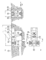
- a multi-stage locking arrangement for optionally locking a roadway (12) is shown to ensure that unauthorized or violent driving on the roadway provided with the locking arrangement (12) is excluded.
- the locking arrangement comprises two differently designed locking devices (10) and (11), which are recessed flush into the road surface at a distance from one another or can be pivoted out of it.
- the locking arrangement according to the invention ensures that vehicles that should have partially overcome the outer locking device (10) cannot tip forward onto the road (12), but are held in a raised position by the second locking device (11) that objects, for example located on a loading area of a vehicle, cannot be thrown in the direction of the area to be blocked.
- FIGS. 2 to 7 Detailed representations of the locking devices (10) and (11) can be found in FIGS. 2 to 7, which will be discussed in more detail below.
- the first locking device (10) comprises three locking elements (20), 22), (24), each pivotable about an axis (14) (16) or (18).
- the axes (14), (16), (18) run in the longitudinal direction of the carriageway (12), so that the blocking elements (20), (22), (24), which are posts, perpendicular to the normal direction of travel from the carriageway ( 12) can be swiveled out.
- Each post (20), (22), (24) is assigned a counter element or counterweight (26), (28), (30) which, regardless of the position of the post (20), (22), (24) is arranged underground.
- the pivot axes (14), (16), 18), which run in the area of the counter elements (26), (28), (30), are also preferably in the area of the center of gravity of the elements (20), (26) and (22), (28) and (24), 30) arranged masses.
- the pivoting therefore takes place via a linkage, such as push rods (34), starting from a drive element such as hydraulic cylinder (32), which in points (36), (38), (40) on the counter elements (26), (28) , (30) articulated and if necessary. is or are divided.
- the hydraulic cylinder (30) is preferably actuated from a metal weather protection housing (42) in order to pivot or lower the locking elements (20), (22), (24) out of the roadway (12) if necessary.
- the posts (20), (22) are arranged in the region of the pivot axes (14), (16), (18), above them overlapping each other and are supported on one another, so that this results in an extremely simple but statically unobjectionable construction is made available.
- the mutually associated ends (48), (50) - shown by way of example on the posts (20) and (22) - have step-shaped recesses (44) and (46) which complement one another. This allows the ends (48), (50) to lie on one another above the axis (36) without the side surfaces (52), (54), (56) of the bollards (20), (22), (24) which are flush with the road surface must show unevenness.
- the front end (62) of the blocking element (20) which does not interact with an adjacent post is supported on a concrete projection (60) in order to achieve sufficient stability in this respect.
- FIG. 8 shows a sectional view of the locking element (24) according to the invention with counter element (30) in order to clarify its structure.
- Both the blocking element (24) and the counter element (30) consist of a double-T support, the flanges (118) and (120) or (122) and (124) of which are welded together.
- the flanges (118) and (112) are welded to the outside with flat iron (only the flat iron (126) is shown) in order to provide a post which is closed on all sides as a blocking element (24).
- Reinforcing ribs can also be welded within the chamber formed by the flanges (118) and (122) and the flat iron in order to give the locking element an even higher rigidity.
- the chamber of the respective double-T beam is closed by flat iron.
- the projections provided in the free ends (50) have the effect that the material impacting against the bollard is penetrated in a cutting-like manner.
- Fig. 7 the locking device (10) according to the invention is shown in an exploded view to illustrate its installation and removal from a roadway.
- a trench (128) is first dug in the roadway (12), the bottom (130) of which is given a concrete ceiling.
- a frame (132) with lost formwork (134), which can be made of sheet metal, is then inserted into the trench (128), so that the space between the lost formwork (134) and the trench is then filled with concrete.
- This provides a frame for the unit (136), which the locking elements (20), (22), (24) and (25) with the counter elements (26), (28), (30) and (31) which comprise these pivoting push rods and the drive device in the form of the hydraulic cylinder (not shown in each case).
- the hydraulic cylinders can be connected to the drive fluid by plug connections in order to make the locking device (10) ready for operation. If one of the locking elements should become inoperable due to a defect, for example, or maintenance should take place, the unit (136) only has to be removed from the frame (132) and then placed on these cover elements such as drive-over bridges so that the roadway (12) can still be driven on is. This ensures that even if the locking device (10) does not work properly, the roadway (12) can be quickly made accessible again to vehicles, an advantage which the locking devices which can be found in the prior art do not offer.
- the locking elements (20), (22) with counter-elements (26) and (28) as well as pivot axes (14) and (16) shown isolated at the top left in FIG. 7 have pipe socket-shaped projections (138) and (140) running at right angles to their longitudinal axes. on. These bridle the area between the adjacent locking elements, so that the locking device (10) also forms an effective drive-through lock for two-wheelers.
- the unit (136) which is also provided as an underfloor installation unit and in FIG. 2 with the reference number (58), preferably has a hot-dip galvanized support structure made of U-shaped and double-T iron, which is designed to withstand the loads.
- the construction is basically chosen so that each bollard loads 100 tons at one speed speed of a vehicle withstands 30 km / h without the swiveling being influenced in any way.
- the double-T beams of the locking elements themselves have leg lengths of preferably 300 mm, the height of the area protruding from the road surface being of the order of 650 mm. This height is sufficient to reach at least the axle area of almost all vehicles, so that in the event of a vehicle collision it becomes unfit to drive.
- the accessible side surfaces (52), (54), (56) of the bollards (20), (22), (24) can be provided with a corrugated sheet (not shown).
- the control for the hydraulic cylinder (32) and the pressure design is selected so that a control with a 24 volt battery is maintained in the event of a power failure, with repeated actuation of the locking bars (20), (22), (24) via an energy store is.
- lowering of the locking bars (20), (22), (24) can be made possible in an emergency by means of a hand pump. Accordingly, the locking device (10) can be described as self-sufficient.
- the second locking device (11) is shown in detail, which comprises a ramp-shaped element (64) which can be pivoted out of the roadway (12) and which can be actuated by a hydraulic cylinder (68) arranged in a shaft (66) .
- the element (64) consists in the exemplary embodiment of a steel plate (70) which is held by two U-steel profiles (72) and (74).
- the longitudinal axis of the U-steel profiles (72) and (74) runs in the longitudinal direction of the carriageway (12).
- the element (64) which is aligned with the roadway (12) when retracted, can be rotated about an axis (76), the shaft (78) required for this passing through the U-steel profiles (72) and (74).
- the hydraulic cylinder (68) also engages in one the U-steel profiles (72) and (74) extending shaft (80) so as to pivot the element (64) out of the road surface or to align with it.
- the element (64) to the first blocking stage (10) is ramp-shaped, i.e. the axis of rotation (76) is closer to the first stage than the shaft (80).
- the edge (82) of the roadway (12) surrounding the element (64) is also preferably made of sheet steel in order to make it easy to maintain.
- the element (64) is preferably arranged in the central region of the carriageway (12), so that effective protection is ensured against vehicles which have at least partially overcome the first blocking stage (10), that is to say on this sit on and run the risk of tipping forward.
- the element (64) has a width of 400 mm and a length of 1200 mm, whereby swinging out over the road surface should be 600 mm.
Landscapes
- Engineering & Computer Science (AREA)
- Architecture (AREA)
- Civil Engineering (AREA)
- Structural Engineering (AREA)
- Refuge Islands, Traffic Blockers, Or Guard Fence (AREA)
Priority Applications (1)
| Application Number | Priority Date | Filing Date | Title |
|---|---|---|---|
| AT86117525T ATE61431T1 (de) | 1985-12-20 | 1986-12-16 | Sperrvorrichtung fuer eine temporaere sperrung einer fahrbahn. |
Applications Claiming Priority (4)
| Application Number | Priority Date | Filing Date | Title |
|---|---|---|---|
| DE3545507 | 1985-12-20 | ||
| DE19853545507 DE3545507A1 (de) | 1985-12-20 | 1985-12-20 | Sperrvorrichtung fuer eine temporaere sperrung einer fahrbahn |
| DE19868628876 DE8628876U1 (de) | 1986-10-29 | 1986-10-29 | Sperrvorrichtung für eine temporäre Sperrung einer Fahrbahn |
| DE8628876U | 1986-10-29 |
Publications (3)
| Publication Number | Publication Date |
|---|---|
| EP0227016A2 true EP0227016A2 (fr) | 1987-07-01 |
| EP0227016A3 EP0227016A3 (en) | 1988-05-25 |
| EP0227016B1 EP0227016B1 (fr) | 1991-03-06 |
Family
ID=25839195
Family Applications (1)
| Application Number | Title | Priority Date | Filing Date |
|---|---|---|---|
| EP86117525A Expired - Lifetime EP0227016B1 (fr) | 1985-12-20 | 1986-12-16 | Dispositif de barrage pour barrer temporairement une chaussée |
Country Status (5)
| Country | Link |
|---|---|
| US (1) | US4775261A (fr) |
| EP (1) | EP0227016B1 (fr) |
| DE (1) | DE3677918D1 (fr) |
| ES (1) | ES2021584B3 (fr) |
| IL (1) | IL81038A (fr) |
Families Citing this family (23)
| Publication number | Priority date | Publication date | Assignee | Title |
|---|---|---|---|---|
| FR2606049B1 (fr) * | 1986-11-04 | 1993-03-12 | Mothe Gerard | Barriere anti-intrusion modulaire |
| US5009542A (en) * | 1990-03-06 | 1991-04-23 | Hardin Jr Paul W | Traffic barrier gate |
| US5211503A (en) * | 1991-04-24 | 1993-05-18 | Energy Absorptions Systems, Inc. | Barrier gate for longitudinal highway barrier |
| GB2282623A (en) * | 1993-10-06 | 1995-04-12 | Seal Boldizsar Edward | Vehicle Barrier |
| GB9321049D0 (en) * | 1993-10-12 | 1993-12-01 | J & R Steel Fabricators Limite | Improvements in or relating to traffic control arrangements |
| US5482397A (en) * | 1994-02-18 | 1996-01-09 | Eagle Research Group, Inc. | Tire deflator and method of deflating a tire |
| RU2101659C1 (ru) * | 1994-11-16 | 1998-01-10 | Вячеслав Александрович Самохвалов | Заградитель для автомототранспорта |
| US5509753A (en) * | 1994-11-22 | 1996-04-23 | Thompson; Clinton C. | Retractable speed bump |
| ES2123364B1 (es) * | 1995-04-03 | 1999-09-16 | Doblado Perez Angel | Obstaculo anti-intrusion de vehiculos con barrera auxiliar de señalizacion. |
| DE10256199B4 (de) * | 2002-12-02 | 2004-11-18 | Linde, Albrecht von, Dr. | Vorrichtung und Verfahren zur Veränderung der Streckenführung einer Fahrzeugrennstrecke |
| US7214000B2 (en) * | 2004-11-03 | 2007-05-08 | The United States Of America As Represented By The Secretary Of The Army | On-grade barrier and method of its use |
| US7530759B2 (en) * | 2004-11-17 | 2009-05-12 | Universal Safety Response, Inc. | Retractable energy absorbing system |
| US7264417B1 (en) | 2006-03-23 | 2007-09-04 | Nasatka Barrier, Inc. | Vehicle barrier system, and related method |
| GB0619391D0 (en) * | 2006-10-02 | 2006-11-08 | Siddall Robert J | Vehicle road barrier |
| US7950870B1 (en) | 2008-03-28 | 2011-05-31 | Energy Absorption Systems, Inc. | Energy absorbing vehicle barrier |
| US20100003078A1 (en) * | 2008-07-07 | 2010-01-07 | National Taipei University Of Technology | Anti-terror car-attack defending apparatus |
| US8056174B2 (en) * | 2009-09-14 | 2011-11-15 | Midwest Industrial Door, Inc. | Repositionable pit seal |
| US8128310B2 (en) * | 2009-09-29 | 2012-03-06 | Unified Designs, Inc. | Vehicle restraint system |
| US8439594B1 (en) | 2011-04-19 | 2013-05-14 | Secureusa, Inc. | Shallow flush-mounted vehicle control barrier |
| KR101399582B1 (ko) * | 2014-03-06 | 2014-06-27 | (주)건설표준시험원 | 안전사고 방지를 위한 도로시설물 |
| US9677232B2 (en) * | 2015-09-17 | 2017-06-13 | Robert C. Zwerneman | Retractable speed barrier |
| US10648141B2 (en) * | 2016-08-10 | 2020-05-12 | The Board Of Regents Of The Nevada System Of Higher Education On Behalf Of The University Of Nevada, Las Vegas | Automated rumble strip assembly |
| US10829900B2 (en) * | 2016-08-10 | 2020-11-10 | The Board Of Regents Of The Nevada System Of Higher Education On Behalf Of The University Of Nevada, Las Vegas | Automated rumble strip assembly |
Family Cites Families (15)
| Publication number | Priority date | Publication date | Assignee | Title |
|---|---|---|---|---|
| US1203006A (en) * | 1914-02-24 | 1916-10-31 | Margaret A Keenan | Apparatus for stopping vehicles. |
| US1356922A (en) * | 1920-02-03 | 1920-10-26 | John J Keenan | Apparatus for stopping vehicles |
| US1365165A (en) * | 1920-08-05 | 1921-01-11 | Garcia Felice Anthony | Gate |
| US1497073A (en) * | 1921-03-16 | 1924-06-10 | Conan A Doyle | Traffic regulator |
| US1579125A (en) * | 1923-12-12 | 1926-03-30 | William R Marshall | Stock guard for roadways |
| DE2048780C3 (de) * | 1970-10-05 | 1975-02-13 | Heinrich 4812 Brackwede Kirschbaum | Quer zur Fahrbahn, insbesondere vor Verkehrsampeln angeordnete Absperrvorrichtung |
| DE2158977C3 (de) * | 1971-11-27 | 1974-10-03 | Fischer Stahlbau, 4000 Duesseldorf | Ausfahrbare Sperre zum vorübergehenden Absperren von Straßen, Plätzen od.dgl |
| US3805448A (en) * | 1971-12-08 | 1974-04-23 | R Carr | Vehicular traffic control apparatus |
| DE2806013A1 (de) * | 1978-02-14 | 1979-08-23 | Malkmus Doernemann Carola | Wege- oder strassensperre fuer fahrzeuge |
| DE2930091A1 (de) * | 1979-07-25 | 1981-02-12 | Hanns Ing Grad Glahn | Kippschwelle gegen falsches befahren von einbahnstrassen |
| NL8201604A (nl) * | 1982-04-16 | 1983-11-16 | Pieter Arie Jan Eikelenboom En | Inzinkbare wegversperring. |
| NL8203450A (nl) * | 1982-09-03 | 1984-04-02 | Peter Johan Geensen | Scharnierbare wegversperring. |
| US4490068A (en) * | 1983-04-25 | 1984-12-25 | Dickinson Harry D | Hydraulic safety barrier traffic-way controller |
| CH660896A5 (de) * | 1983-06-13 | 1987-05-29 | Burri Ag | Fahrbahn-abschrankungsstrecke. |
| US4577991A (en) * | 1984-11-28 | 1986-03-25 | Rolow Willard J | Deployable vehicular barricade |
-
1986
- 1986-12-16 ES ES86117525T patent/ES2021584B3/es not_active Expired - Lifetime
- 1986-12-16 DE DE8686117525T patent/DE3677918D1/de not_active Expired - Lifetime
- 1986-12-16 EP EP86117525A patent/EP0227016B1/fr not_active Expired - Lifetime
- 1986-12-18 US US06/943,640 patent/US4775261A/en not_active Expired - Lifetime
- 1986-12-19 IL IL81038A patent/IL81038A/xx not_active IP Right Cessation
Also Published As
| Publication number | Publication date |
|---|---|
| EP0227016A3 (en) | 1988-05-25 |
| IL81038A (en) | 1991-05-12 |
| ES2021584B3 (es) | 1991-11-16 |
| DE3677918D1 (de) | 1991-04-11 |
| US4775261A (en) | 1988-10-04 |
| EP0227016B1 (fr) | 1991-03-06 |
| IL81038A0 (en) | 1987-03-31 |
Similar Documents
| Publication | Publication Date | Title |
|---|---|---|
| EP0227016B1 (fr) | Dispositif de barrage pour barrer temporairement une chaussée | |
| DE69223511T2 (de) | Autobahnleitwand aus miteinander verbindbaren Abschnitten | |
| DE68901702T2 (de) | Modulare konstruktion fuer parkplaetze, insbesondere fuer zeitlich begrenzt benutzte parkplaetze. | |
| DE202018103084U1 (de) | Mobile Straßensperre | |
| DE2908818A1 (de) | Abbaubare barriere | |
| DE3816644A1 (de) | Sperrpfosten | |
| DE68904949T2 (de) | Verfahren und Bauelemente zum Errichten von unterirdischen Garagen. | |
| EP0999307B1 (fr) | Ensemble de tunnels routiers pour l'établissement d'un réseau routier dans des zones urbanisées | |
| EP0556609B1 (fr) | Quai ferroviaire | |
| DE102008049966C5 (de) | Anschluss für eine Verkehrsleitwand | |
| DE3012680A1 (de) | Stahlschutzplanke | |
| DE4040589C2 (fr) | ||
| DE3412354C2 (fr) | ||
| DE3611372A1 (de) | Strassensperre | |
| DE4345415C2 (de) | Montagegrube mit doppelwandiger Stahlkassette | |
| EP2711462B1 (fr) | Portique de signalisation | |
| EP2333160A1 (fr) | Dispositif de guidage de la circulation | |
| DE8628876U1 (de) | Sperrvorrichtung für eine temporäre Sperrung einer Fahrbahn | |
| DE2503630A1 (de) | Stauwand und verfahren zum aufbau derselben | |
| DE4402950A1 (de) | Verfahren und Vorrichtung zum Bau wenigstens einer oberen Fahrbahnebene mit wenigstens einer Fahrbahn | |
| DE3545507A1 (de) | Sperrvorrichtung fuer eine temporaere sperrung einer fahrbahn | |
| DE3203980C2 (de) | Unterführungsbauwerk sowie Verfahren zu seiner Herstellung | |
| EP4299833B1 (fr) | Système de retenue et/ou de protection contre le bruit de véhicule avec fondation préfabriquée | |
| DE3130568C1 (de) | Streckendurchbauvorrichtung | |
| EP3680388B1 (fr) | Protection d'accès |
Legal Events
| Date | Code | Title | Description |
|---|---|---|---|
| PUAI | Public reference made under article 153(3) epc to a published international application that has entered the european phase |
Free format text: ORIGINAL CODE: 0009012 |
|
| AK | Designated contracting states |
Kind code of ref document: A2 Designated state(s): AT BE CH DE ES FR GB GR IT LI LU NL SE |
|
| PUAL | Search report despatched |
Free format text: ORIGINAL CODE: 0009013 |
|
| AK | Designated contracting states |
Kind code of ref document: A3 Designated state(s): AT BE CH DE ES FR GB GR IT LI LU NL SE |
|
| 17P | Request for examination filed |
Effective date: 19880903 |
|
| 17Q | First examination report despatched |
Effective date: 19891017 |
|
| GRAA | (expected) grant |
Free format text: ORIGINAL CODE: 0009210 |
|
| AK | Designated contracting states |
Kind code of ref document: B1 Designated state(s): AT BE CH DE ES FR GB GR IT LI LU NL SE |
|
| PG25 | Lapsed in a contracting state [announced via postgrant information from national office to epo] |
Ref country code: GR Free format text: LAPSE BECAUSE OF FAILURE TO SUBMIT A TRANSLATION OF THE DESCRIPTION OR TO PAY THE FEE WITHIN THE PRESCRIBED TIME-LIMIT Effective date: 19910306 |
|
| REF | Corresponds to: |
Ref document number: 61431 Country of ref document: AT Date of ref document: 19910315 Kind code of ref document: T |
|
| REF | Corresponds to: |
Ref document number: 3677918 Country of ref document: DE Date of ref document: 19910411 |
|
| ITF | It: translation for a ep patent filed | ||
| GBT | Gb: translation of ep patent filed (gb section 77(6)(a)/1977) | ||
| ET | Fr: translation filed | ||
| PLBE | No opposition filed within time limit |
Free format text: ORIGINAL CODE: 0009261 |
|
| STAA | Information on the status of an ep patent application or granted ep patent |
Free format text: STATUS: NO OPPOSITION FILED WITHIN TIME LIMIT |
|
| 26N | No opposition filed | ||
| EPTA | Lu: last paid annual fee | ||
| PGFP | Annual fee paid to national office [announced via postgrant information from national office to epo] |
Ref country code: SE Payment date: 19941123 Year of fee payment: 9 |
|
| PGFP | Annual fee paid to national office [announced via postgrant information from national office to epo] |
Ref country code: GB Payment date: 19941206 Year of fee payment: 9 |
|
| PGFP | Annual fee paid to national office [announced via postgrant information from national office to epo] |
Ref country code: BE Payment date: 19941209 Year of fee payment: 9 |
|
| PGFP | Annual fee paid to national office [announced via postgrant information from national office to epo] |
Ref country code: ES Payment date: 19941215 Year of fee payment: 9 |
|
| PGFP | Annual fee paid to national office [announced via postgrant information from national office to epo] |
Ref country code: FR Payment date: 19941230 Year of fee payment: 9 |
|
| PGFP | Annual fee paid to national office [announced via postgrant information from national office to epo] |
Ref country code: NL Payment date: 19941231 Year of fee payment: 9 |
|
| EAL | Se: european patent in force in sweden |
Ref document number: 86117525.5 |
|
| PGFP | Annual fee paid to national office [announced via postgrant information from national office to epo] |
Ref country code: AT Payment date: 19951212 Year of fee payment: 10 |
|
| PG25 | Lapsed in a contracting state [announced via postgrant information from national office to epo] |
Ref country code: GB Effective date: 19951216 |
|
| PG25 | Lapsed in a contracting state [announced via postgrant information from national office to epo] |
Ref country code: SE Effective date: 19951217 |
|
| PG25 | Lapsed in a contracting state [announced via postgrant information from national office to epo] |
Ref country code: ES Free format text: LAPSE BECAUSE OF EXPIRATION OF PROTECTION Effective date: 19951218 |
|
| PG25 | Lapsed in a contracting state [announced via postgrant information from national office to epo] |
Ref country code: BE Effective date: 19951231 |
|
| BERE | Be: lapsed |
Owner name: MANFRED FLADUNG G.M.B.H. Effective date: 19951231 |
|
| PG25 | Lapsed in a contracting state [announced via postgrant information from national office to epo] |
Ref country code: NL Effective date: 19960701 |
|
| GBPC | Gb: european patent ceased through non-payment of renewal fee |
Effective date: 19951216 |
|
| PG25 | Lapsed in a contracting state [announced via postgrant information from national office to epo] |
Ref country code: FR Effective date: 19960830 |
|
| NLV4 | Nl: lapsed or anulled due to non-payment of the annual fee |
Effective date: 19960701 |
|
| REG | Reference to a national code |
Ref country code: FR Ref legal event code: ST |
|
| PG25 | Lapsed in a contracting state [announced via postgrant information from national office to epo] |
Ref country code: AT Effective date: 19961216 |
|
| PGFP | Annual fee paid to national office [announced via postgrant information from national office to epo] |
Ref country code: LU Payment date: 19981211 Year of fee payment: 13 |
|
| PG25 | Lapsed in a contracting state [announced via postgrant information from national office to epo] |
Ref country code: LU Free format text: LAPSE BECAUSE OF NON-PAYMENT OF DUE FEES Effective date: 19991216 |
|
| REG | Reference to a national code |
Ref country code: ES Ref legal event code: FD2A Effective date: 20010301 |
|
| PGFP | Annual fee paid to national office [announced via postgrant information from national office to epo] |
Ref country code: DE Payment date: 20050128 Year of fee payment: 19 |
|
| PGFP | Annual fee paid to national office [announced via postgrant information from national office to epo] |
Ref country code: CH Payment date: 20050323 Year of fee payment: 19 |
|
| PG25 | Lapsed in a contracting state [announced via postgrant information from national office to epo] |
Ref country code: IT Free format text: LAPSE BECAUSE OF NON-PAYMENT OF DUE FEES;WARNING: LAPSES OF ITALIAN PATENTS WITH EFFECTIVE DATE BEFORE 2007 MAY HAVE OCCURRED AT ANY TIME BEFORE 2007. THE CORRECT EFFECTIVE DATE MAY BE DIFFERENT FROM THE ONE RECORDED. Effective date: 20051216 |
|
| PG25 | Lapsed in a contracting state [announced via postgrant information from national office to epo] |
Ref country code: LI Free format text: LAPSE BECAUSE OF NON-PAYMENT OF DUE FEES Effective date: 20051231 Ref country code: CH Free format text: LAPSE BECAUSE OF NON-PAYMENT OF DUE FEES Effective date: 20051231 |
|
| PG25 | Lapsed in a contracting state [announced via postgrant information from national office to epo] |
Ref country code: DE Free format text: LAPSE BECAUSE OF NON-PAYMENT OF DUE FEES Effective date: 20060701 |
|
| REG | Reference to a national code |
Ref country code: CH Ref legal event code: PL |