US4775261A - Barrier device for the temporary blocking of a roadway - Google Patents
Barrier device for the temporary blocking of a roadway Download PDFInfo
- Publication number
- US4775261A US4775261A US06/943,640 US94364086A US4775261A US 4775261 A US4775261 A US 4775261A US 94364086 A US94364086 A US 94364086A US 4775261 A US4775261 A US 4775261A
- Authority
- US
- United States
- Prior art keywords
- barrier
- barrier elements
- elements
- ramp
- roadway
- Prior art date
- Legal status (The legal status is an assumption and is not a legal conclusion. Google has not performed a legal analysis and makes no representation as to the accuracy of the status listed.)
- Expired - Lifetime
Links
Images




Classifications
-
- E—FIXED CONSTRUCTIONS
- E01—CONSTRUCTION OF ROADS, RAILWAYS, OR BRIDGES
- E01F—ADDITIONAL WORK, SUCH AS EQUIPPING ROADS OR THE CONSTRUCTION OF PLATFORMS, HELICOPTER LANDING STAGES, SIGNS, SNOW FENCES, OR THE LIKE
- E01F13/00—Arrangements for obstructing or restricting traffic, e.g. gates, barricades ; Preventing passage of vehicles of selected category or dimensions
- E01F13/04—Arrangements for obstructing or restricting traffic, e.g. gates, barricades ; Preventing passage of vehicles of selected category or dimensions movable to allow or prevent passage
- E01F13/08—Arrangements for obstructing or restricting traffic, e.g. gates, barricades ; Preventing passage of vehicles of selected category or dimensions movable to allow or prevent passage by swinging into closed position about a transverse axis situated in the road surface, e.g. tiltable sections of the road surface, tiltable parking posts
Definitions
- the invention relates to a barrier device for the temporary blocking of a roadway or such, comprising barrier elements which by choice can be either in the main arranged flush with the surface of the roadway or can be swung out of it, whereby each barrier element is pivotable around an axle running in the main parallel to the main highway direction, said barrier element being joined to a counter-element present below or in the main below the roadway surface.
- Corresponding traffic barriers for the temporary blocking of free highways can comprise prism-shaped barriers extending along the breadth of the highway and which can be swung out of the highway in order to protect grounds in need of protection--e.g. public or private supply centres or power installations--against illegal or violent entry by motor vehicles or bicycles.
- Said barriers which can also be termed blocking elements, are very large, maintenance intensive and when hit by a vehicle are fundamentally no longer in working order, i.e. the blocking element can no longer be sunk into the roadway. In the case of a disaster this results however in the area which is to be protected being blocked off, which is to be avoided at all costs.
- An aim of the present invention is to design a barrier device as previously described, so that with minimum measuring of the simple blocking elements it is ensured that illegal driving on the roadway--regardless as to from which direction--can be prevented, whereby with regard to the construction and consequently functionability, a high degrees of reliability and ease of maintenance should be guaranteed.
- a further object of the invention is that the blocking element should only render a vehicle incapable of being driven when it has hit the barrier element, without the life of the driver being endangered.
- the object is on the one hand solved in that the elements are posts, which, when they are in the main flush with the roadway surface, overlap and lie on each other above the axle.
- the pivot axle extends preferably in the counter-element, preferably in the area of the centre of gravity of the element and counter-element, so that little force is necessary to permit pivoting.
- the said elements combine with a rod which is operated by a drive element such as a hydraulic cylinder, which is preferably coupled in the area of the counter-elements.
- a drive element such as a hydraulic cylinder
- the control of the hydraulic cylinder is so arranged that an energy store also guarantees that the barrier elements can be operated during an electricity cut, since only a 24V battery is for example necessary for the control itself.
- a hand pump can be provided to lower the barrier elements in an emergency, i.e. to pivot them on the axle extending parallel to the longitudinal direction of the highway.
- the sections of the barrier elements lying on top of each other, i.e. the overlapping areas, are formed by recesses--which complete each other in a complementary fashion--of the post elements allocated to each other, whereby the recesses themselves are preferably of a graduated shape.
- the barrier elements themselves, and preferably also the counter-elements, consist of double-T girders with an edge length of 300 mm for example, whereby at least the flanges of the barrier elements are joined with flat bars and between these and the rails have reinforcing ribs.
- the height of the posts above the highway is preferably 650 mm, which ensures that the axles of vehicles hitting the barrier elements are damaged to such an extent that they are unable to drive away independantly. Posts of such a design withstand forces of 100 tons at a speed of 30 km per hour.
- the surfaces of the barrier elements, over which vehicles will drive when the elements are in their aligned or flush position, may advantageously be ridged or of checkered plate.
- At least the blocking element has an acute-angled rectangular form, whereby the free end is equipped with a rectangular-shaped recess to form a tooth.
- the blocking elements, together with the rod can be set as a unit in a frame and are interchangeable, whereby the frame is equipped with a dead mould, which can be inserted in a pit present in the highway, whereby preferably the motor driving the rod can be inserted into the frame interchangeably together with the unit.
- the fitting of the barrier device is completely trouble-free.
- a pit has only to be excavated out of the roadway and the ground to be cast with a cement floor in order to fit the frame with the dead mould, which consists of sheet metal. This is then cemented, which guarantees a high degree of accuracy.
- the barrier elements held by a supporting construction can be fitted with the counter-elements as well as the rods and drive equipment, and for example in the case of maintenance work can be removed again as a unit.
- the frame only has to be then covered with a ramp which can be driven over, and then the roadway is clear even during maintenance work.
- the underground supporting construction (assembly unit) containing the elements in a pivotable fashion is hot-dip galvanised and is statically equipped in accordance with the strains to be expected.
- All rotating parts are provided with lubricating devices, whereby the bearings themselves are manufactured from high-quality bearing material in order to guarantee a high degree of efficiency even with extreme strain.
- braces can emanate from the lateral surfaces at right angles and extend in the direction of the neighbouring post, thus guaranteeing that bicycles for example cannot pass through the barrier elements.
- this characteristic it must be mentioned that the area between the pivoted barrier elements is not covered over, the resulting opening thus representing a further obstacle.
- the interchangeable unit preferably comprises three barrier elements; in the case of wider highway area having to be protected several units can be set in a row.
- the barrier device comprises at least two stages; one stage being formed by the barrier elements and the other stage being forced by at least one ramp-like element which can be swung out of the roadway and which is set at a distance to and behind the barrier elements in the driving direction.
- the barrier device according to the invention is particularly suitable for use in military or diplomatic installations, which have to be effectively protected, for example against bomb attacks.
- the element is preferably arranged in the centre of the roadway, so that it is unnecessary to place several side by side.
- the elements forming the second stage into the roadway staggered to each other, thus forming an effective barrier for vehicles of varying sizes.
- the ramp-like functioning element can be formed by at least two U-shaped iron sections in the longitudinal direction of the roadway, on which a steel plate is arranged which is flush with the roadway surface.
- the element which can be pivoted out of the roadway surface, combines preferably with a hydraulic cylinder. It is furthermore proposed that the edge areas of the roadway surface encompassing the element are also made of steel plates, resulting in ease of maintenance.
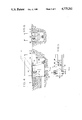
- FIG. 1 a principle representation of arrangements of barrier devices
- FIG. 2 a detailed representation of a barrier device with sunken barrier elements
- FIG. 3 the barrier device according to FIG. 2 with barrier elements swung out
- FIG. 4 a detailed representation of a barrier ramp
- FIG. 5 a top view of the barrier ramp according to FIG. 4
- FIG. 6 a sectional representation along the line AA in FIG. 5
- FIG. 7 an enlarged representation of a barrier device according to FIG. 1 and
- FIG. 8 a sectional representation along the line VIII--VIII in FIG. 2.
- FIG. 1 represents a multi-staged barrier arrangement for the blocking of a roadway (12) by choice in order to ensure that unauthorised or violent access to the highway equipped with the barrier arrangement is prevented.
- the barrier arrangement comprises two barrier devices (10) and (11), of varying design which are set into the highway surface flush with it and at a distance to each other or can be swung out of the highway surface.
- the barrier arrangement according to the invention ensures that vehicles which may have overcome the outer barrier device (10) cannot tip forward onto the roadway (12), but are rather held in an upright position by the second barrier device (11), so that object for example on the loading surface of a vehicle cannot be swung in the direction of the area being protected.
- FIGS. 2 to 7 Detailed representations of the barrier devices (10) and (11) are containedin FIGS. 2 to 7, which are to be described in more detail as follows.
- the first barrier device comprises three blocking elements (20, 22, 24), which each pivot around anaxle (14, 16, or 18).
- the axles (14, 16, 18) extend in the longitudinal direction of the highway (12), so that the blocking elements (20, 22, 24),which are posts, can be swung out of the highway (12) vertical to the normal travelling direction.
- Each post (20, 22, 24) has a counter-element or counter-weight (26, 28, 30) coordinating with it, which is arranged below ground independant of the position of the posts (20, 22, 24).
- the swing axles (14, 16, 18) extending in the area of the counter-elements (26, 28, 30) are moreover preferably arranged in the area of the centre ofgravity of the masses assembled by the elements (20, 26 or resp. 22, 28 or resp. 24, 30).
- This facilitates the pivotability of the barrier elements (20, 22, 24) with the counter-elements (26, 28, 30). Therefore pivoting results via a rod such as combining rods (34) which emanate from a motor organ such as a hydraulic cylinder (32); rod or rods being linked to the counter-elements (26, 28, 30) in the points (36, 38, 40) and if necessary sectioned.
- Operation of the hydraulic cylinder (32) takes places preferably from a metal cabin (42), so that when necessary the blocking elements (20, 22, 24) are swung out of the highway (12) or sunk into it.
- the posts (20, 22, 24) are in the area of the swing axles (14, 46,18) and are arranged in an overlapping manner above the said swing axles and support each other, resulting in a completely simple but yet statically sound construction.
- FIG. 8 shows a sectional representation of the barrier element (24) according to the invention with the counter-element (30), in order to clarify their construction.
- the barrier element (24) as well as the counter-element (30) consist of a double-T girder whose flanges (118 and 120 or 122 and 124) are welded together.
- the flanges (118 and 122) are welded on the exterior with flat steels (only flat steel (126) is represented), thus providing a post enclosed on all sides as a barrier element (24).
- reinforcing ribs can be welded inside the chamber formed by the flanges (118 and 122) and the flat steels to providethe barrier element with increased rigidity.
- the chamber of the relevant double-T girders is also closed off by flat steels in the area of the free outer ends of the barrier elements.Furthermore it should be noted that the protrusions provided in the free ends (50) cause material bouncing against the barrier posts to be penetrated in a cutting fashion.
- FIG. 7 represents the barrier device (10) according to the invention in a blown-up representation to clarify their insertion into and extraction from the roadway.
- a pit (128) is excavated out of the highway (12), on the floorof which (130) a cement floor is laid. Then a frame (132) is inserted into it with a dead mould (134) which can be made of sheet metal, so that finally the cavity between the dead mould (134) and the pit can be filled with cement.
- This provides a frame for the unit (136) which comprises the barrier elements (20, 22, 24 and 25) withthe counter-elements (26, 28, 30 and 31), the combining rods pivoting these as well as the drive equipment in the form of a hydraulic cylinder (in each case not represented). If this unit (136) is set on the frame (132) and screwed to it, the hydrauliccylinder can be connected with driving fluid, thus rendering the barrier device operational.
- the unit (136) simply has to be disconnected from the frame (132) and finally covering elements such as ramps have to be laid on the frame so that the roadway (12) can continue to be used. This guarantees that even in the case of a barrier device (10) not operating correctly the highway can be quickly cleared again for vehicles; an advantage not contained in the corresponding barrier devices to be drawn from the state of the art.
- the barrier elements (20, 22) represented alone at the top left in FIG. 7 with counter-elements (26 and 28) as well as pivot axles (14 and 16) have pipe support-shaped protrusions (138 and 140) running at right angles to their longitudinal axes. These block the area between the barrier elementsstanding adjacent, so that the barrier element (10) also forms an effectivebarrier blocking access for bicycles.
- the passable lateral areas (52, 54, 56) of the blocking posts (20, 22, 24) can be provided with a checkered plate which is not represented.
- Control for the hydraulic cylinder (32) and the pressure lay-out is chosen so that in the case of an electricity cut control can be maintained by a 24V battery, whereby operation of the barrier elements (20, 22, 24) several times is guaranteed by an energy storage unit. Furthermore in an emergency the barrier elements (20, 22, 24) can be sunk by means of a handpump. Consequently the barrier device (10) can be designated as being self-sufficient.
- the hydraulic cylinder (68) engages into a shaft (80) also extending between the U-shaped steel sections (72 and 74) in order to thus swing the element (64) out of the highway surfaceor to render the element flush with it to the required extent.
- the element (64) is designed ramp-like to the first barrier stage (10), i.e. the pivoting axle (76) lies nearer to the first stage than the shaft (80).
- the edge (82) of the roadway (12) enclosing the element (64) is also preferably made of sheet metal to provide ease of maintenance.
- the element (64) is preferably arranged in the middleof the roadway (12) so that effective protection is guaranteed against vehicles which at least have partly overcome the first barrier (10), ie. are sitting on top of it and are in danger of tipping forwards.
- the element (64) is 400 mm wide and 1200 mm long, whereby the swing area of the highway surface should be 600 mm.
Landscapes
- Engineering & Computer Science (AREA)
- Architecture (AREA)
- Civil Engineering (AREA)
- Structural Engineering (AREA)
- Refuge Islands, Traffic Blockers, Or Guard Fence (AREA)
Applications Claiming Priority (4)
| Application Number | Priority Date | Filing Date | Title |
|---|---|---|---|
| DE3545507 | 1985-12-20 | ||
| DE19853545507 DE3545507A1 (de) | 1985-12-20 | 1985-12-20 | Sperrvorrichtung fuer eine temporaere sperrung einer fahrbahn |
| DE19868628876 DE8628876U1 (de) | 1986-10-29 | 1986-10-29 | Sperrvorrichtung für eine temporäre Sperrung einer Fahrbahn |
| DE8628876[U] | 1986-10-29 |
Publications (1)
| Publication Number | Publication Date |
|---|---|
| US4775261A true US4775261A (en) | 1988-10-04 |
Family
ID=25839195
Family Applications (1)
| Application Number | Title | Priority Date | Filing Date |
|---|---|---|---|
| US06/943,640 Expired - Lifetime US4775261A (en) | 1985-12-20 | 1986-12-18 | Barrier device for the temporary blocking of a roadway |
Country Status (5)
| Country | Link |
|---|---|
| US (1) | US4775261A (fr) |
| EP (1) | EP0227016B1 (fr) |
| DE (1) | DE3677918D1 (fr) |
| ES (1) | ES2021584B3 (fr) |
| IL (1) | IL81038A (fr) |
Cited By (23)
| Publication number | Priority date | Publication date | Assignee | Title |
|---|---|---|---|---|
| US4998843A (en) * | 1986-11-04 | 1991-03-12 | Gerard Mothe | Modular anti-intrusion barrier |
| US5009542A (en) * | 1990-03-06 | 1991-04-23 | Hardin Jr Paul W | Traffic barrier gate |
| US5211503A (en) * | 1991-04-24 | 1993-05-18 | Energy Absorptions Systems, Inc. | Barrier gate for longitudinal highway barrier |
| GB2282623A (en) * | 1993-10-06 | 1995-04-12 | Seal Boldizsar Edward | Vehicle Barrier |
| GB2282838A (en) * | 1993-10-12 | 1995-04-19 | J & R Hill | Retractable traffic control barrier |
| US5482397A (en) * | 1994-02-18 | 1996-01-09 | Eagle Research Group, Inc. | Tire deflator and method of deflating a tire |
| US5509753A (en) * | 1994-11-22 | 1996-04-23 | Thompson; Clinton C. | Retractable speed bump |
| WO1996015417A1 (fr) * | 1994-11-16 | 1996-05-23 | Samokhvalov Vyacheslav Alexand | Barriere de trafic |
| ES2123364A1 (es) * | 1995-04-03 | 1999-01-01 | Doblado Perez Angel | Obstaculo anti-intrusion de vehiculos con barrera auxiliar de señalizacion. |
| US20060093431A1 (en) * | 2004-11-03 | 2006-05-04 | Marsh Charles P | On-grade barrier and method of its use |
| US20060104713A1 (en) * | 2004-11-17 | 2006-05-18 | Gelfand Matthew A | Retractable energy absorbing system |
| US20060127174A1 (en) * | 2002-12-02 | 2006-06-15 | Linde Albrecht Von | Device and method for modifying the layout of a vehicle racetrack |
| US7264417B1 (en) | 2006-03-23 | 2007-09-04 | Nasatka Barrier, Inc. | Vehicle barrier system, and related method |
| GB2442590A (en) * | 2006-10-02 | 2008-04-09 | Robert James Siddall | Road barrier |
| US20100003078A1 (en) * | 2008-07-07 | 2010-01-07 | National Taipei University Of Technology | Anti-terror car-attack defending apparatus |
| US20110061185A1 (en) * | 2009-09-14 | 2011-03-17 | Kimener R Peter | Repositionable pit seal |
| US20110076097A1 (en) * | 2009-09-29 | 2011-03-31 | Dindl Frank J | Vehicle Restraint System |
| US7950870B1 (en) | 2008-03-28 | 2011-05-31 | Energy Absorption Systems, Inc. | Energy absorbing vehicle barrier |
| US8439594B1 (en) * | 2011-04-19 | 2013-05-14 | Secureusa, Inc. | Shallow flush-mounted vehicle control barrier |
| US20150252540A1 (en) * | 2014-03-06 | 2015-09-10 | Construc Standard Testing Center Co., Ltd. | Road equipment for preventing traffic accident |
| US9677232B2 (en) * | 2015-09-17 | 2017-06-13 | Robert C. Zwerneman | Retractable speed barrier |
| US20180044866A1 (en) * | 2016-08-10 | 2018-02-15 | The Board of Regents of the Nevada System of Higher Education on Behalf of the Univ. of Nevada | Automated rumble strip assembly |
| US20180163353A1 (en) * | 2016-08-10 | 2018-06-14 | The Board Of Regents Of The Nevada System Of Higher Education On Behalf Of The University Of Ne | Automated rumble strip assembly |
Citations (10)
| Publication number | Priority date | Publication date | Assignee | Title |
|---|---|---|---|---|
| US1203006A (en) * | 1914-02-24 | 1916-10-31 | Margaret A Keenan | Apparatus for stopping vehicles. |
| US1356922A (en) * | 1920-02-03 | 1920-10-26 | John J Keenan | Apparatus for stopping vehicles |
| US1365165A (en) * | 1920-08-05 | 1921-01-11 | Garcia Felice Anthony | Gate |
| US1497073A (en) * | 1921-03-16 | 1924-06-10 | Conan A Doyle | Traffic regulator |
| US1579125A (en) * | 1923-12-12 | 1926-03-30 | William R Marshall | Stock guard for roadways |
| US3805448A (en) * | 1971-12-08 | 1974-04-23 | R Carr | Vehicular traffic control apparatus |
| DE2930091A1 (de) * | 1979-07-25 | 1981-02-12 | Hanns Ing Grad Glahn | Kippschwelle gegen falsches befahren von einbahnstrassen |
| NL8203450A (nl) * | 1982-09-03 | 1984-04-02 | Peter Johan Geensen | Scharnierbare wegversperring. |
| US4490068A (en) * | 1983-04-25 | 1984-12-25 | Dickinson Harry D | Hydraulic safety barrier traffic-way controller |
| US4577991A (en) * | 1984-11-28 | 1986-03-25 | Rolow Willard J | Deployable vehicular barricade |
Family Cites Families (5)
| Publication number | Priority date | Publication date | Assignee | Title |
|---|---|---|---|---|
| DE2048780C3 (de) * | 1970-10-05 | 1975-02-13 | Heinrich 4812 Brackwede Kirschbaum | Quer zur Fahrbahn, insbesondere vor Verkehrsampeln angeordnete Absperrvorrichtung |
| DE2158977C3 (de) * | 1971-11-27 | 1974-10-03 | Fischer Stahlbau, 4000 Duesseldorf | Ausfahrbare Sperre zum vorübergehenden Absperren von Straßen, Plätzen od.dgl |
| DE2806013A1 (de) * | 1978-02-14 | 1979-08-23 | Malkmus Doernemann Carola | Wege- oder strassensperre fuer fahrzeuge |
| NL8201604A (nl) * | 1982-04-16 | 1983-11-16 | Pieter Arie Jan Eikelenboom En | Inzinkbare wegversperring. |
| CH660896A5 (de) * | 1983-06-13 | 1987-05-29 | Burri Ag | Fahrbahn-abschrankungsstrecke. |
-
1986
- 1986-12-16 ES ES86117525T patent/ES2021584B3/es not_active Expired - Lifetime
- 1986-12-16 DE DE8686117525T patent/DE3677918D1/de not_active Expired - Lifetime
- 1986-12-16 EP EP86117525A patent/EP0227016B1/fr not_active Expired - Lifetime
- 1986-12-18 US US06/943,640 patent/US4775261A/en not_active Expired - Lifetime
- 1986-12-19 IL IL81038A patent/IL81038A/xx not_active IP Right Cessation
Patent Citations (10)
| Publication number | Priority date | Publication date | Assignee | Title |
|---|---|---|---|---|
| US1203006A (en) * | 1914-02-24 | 1916-10-31 | Margaret A Keenan | Apparatus for stopping vehicles. |
| US1356922A (en) * | 1920-02-03 | 1920-10-26 | John J Keenan | Apparatus for stopping vehicles |
| US1365165A (en) * | 1920-08-05 | 1921-01-11 | Garcia Felice Anthony | Gate |
| US1497073A (en) * | 1921-03-16 | 1924-06-10 | Conan A Doyle | Traffic regulator |
| US1579125A (en) * | 1923-12-12 | 1926-03-30 | William R Marshall | Stock guard for roadways |
| US3805448A (en) * | 1971-12-08 | 1974-04-23 | R Carr | Vehicular traffic control apparatus |
| DE2930091A1 (de) * | 1979-07-25 | 1981-02-12 | Hanns Ing Grad Glahn | Kippschwelle gegen falsches befahren von einbahnstrassen |
| NL8203450A (nl) * | 1982-09-03 | 1984-04-02 | Peter Johan Geensen | Scharnierbare wegversperring. |
| US4490068A (en) * | 1983-04-25 | 1984-12-25 | Dickinson Harry D | Hydraulic safety barrier traffic-way controller |
| US4577991A (en) * | 1984-11-28 | 1986-03-25 | Rolow Willard J | Deployable vehicular barricade |
Cited By (40)
| Publication number | Priority date | Publication date | Assignee | Title |
|---|---|---|---|---|
| US4998843A (en) * | 1986-11-04 | 1991-03-12 | Gerard Mothe | Modular anti-intrusion barrier |
| US5009542A (en) * | 1990-03-06 | 1991-04-23 | Hardin Jr Paul W | Traffic barrier gate |
| US5211503A (en) * | 1991-04-24 | 1993-05-18 | Energy Absorptions Systems, Inc. | Barrier gate for longitudinal highway barrier |
| GB2282623A (en) * | 1993-10-06 | 1995-04-12 | Seal Boldizsar Edward | Vehicle Barrier |
| GB2282838B (en) * | 1993-10-12 | 1997-02-12 | J & R Hill | Improvements in or relating to traffic control arrangements |
| GB2282838A (en) * | 1993-10-12 | 1995-04-19 | J & R Hill | Retractable traffic control barrier |
| US5482397A (en) * | 1994-02-18 | 1996-01-09 | Eagle Research Group, Inc. | Tire deflator and method of deflating a tire |
| WO1996015417A1 (fr) * | 1994-11-16 | 1996-05-23 | Samokhvalov Vyacheslav Alexand | Barriere de trafic |
| US5509753A (en) * | 1994-11-22 | 1996-04-23 | Thompson; Clinton C. | Retractable speed bump |
| ES2123364A1 (es) * | 1995-04-03 | 1999-01-01 | Doblado Perez Angel | Obstaculo anti-intrusion de vehiculos con barrera auxiliar de señalizacion. |
| US7699559B2 (en) * | 2002-12-02 | 2010-04-20 | Linde Albrecht Von | Device and method for modifying the layout of a vehicle racing course |
| US20060127174A1 (en) * | 2002-12-02 | 2006-06-15 | Linde Albrecht Von | Device and method for modifying the layout of a vehicle racetrack |
| US20060093431A1 (en) * | 2004-11-03 | 2006-05-04 | Marsh Charles P | On-grade barrier and method of its use |
| US20070177940A1 (en) * | 2004-11-03 | 2007-08-02 | Marsh Charles P | On-grade barrier and method of its use |
| US7214000B2 (en) * | 2004-11-03 | 2007-05-08 | The United States Of America As Represented By The Secretary Of The Army | On-grade barrier and method of its use |
| US20090185857A1 (en) * | 2004-11-17 | 2009-07-23 | Gelfand Matthew A | Retractable Energy Absorbing System |
| US7530759B2 (en) | 2004-11-17 | 2009-05-12 | Universal Safety Response, Inc. | Retractable energy absorbing system |
| WO2006055210A3 (fr) * | 2004-11-17 | 2007-02-22 | Universal Safety Response Inc | Systeme escamotable d'absorption d'energie |
| US20060104713A1 (en) * | 2004-11-17 | 2006-05-18 | Gelfand Matthew A | Retractable energy absorbing system |
| AU2005306938B2 (en) * | 2004-11-17 | 2010-06-03 | Smith & Wesson Security Solutions, Inc. | Retractable energy absorbing system |
| US20070223995A1 (en) * | 2006-03-23 | 2007-09-27 | Nasatka Kenneth F | Vehicle barrier system, and related method |
| US7264417B1 (en) | 2006-03-23 | 2007-09-04 | Nasatka Barrier, Inc. | Vehicle barrier system, and related method |
| GB2442590A (en) * | 2006-10-02 | 2008-04-09 | Robert James Siddall | Road barrier |
| US7950870B1 (en) | 2008-03-28 | 2011-05-31 | Energy Absorption Systems, Inc. | Energy absorbing vehicle barrier |
| US8182169B2 (en) | 2008-03-28 | 2012-05-22 | Energy Absorption Systems, Inc. | Energy absorbing vehicle barrier |
| US20100003078A1 (en) * | 2008-07-07 | 2010-01-07 | National Taipei University Of Technology | Anti-terror car-attack defending apparatus |
| US8006338B2 (en) | 2009-09-14 | 2011-08-30 | Midwest Industrial Door, Inc. | Repositionable pit seal |
| US20110061184A1 (en) * | 2009-09-14 | 2011-03-17 | Kimener R Peter | Repositionable pit seal |
| US8056174B2 (en) | 2009-09-14 | 2011-11-15 | Midwest Industrial Door, Inc. | Repositionable pit seal |
| US20110061185A1 (en) * | 2009-09-14 | 2011-03-17 | Kimener R Peter | Repositionable pit seal |
| US20110076097A1 (en) * | 2009-09-29 | 2011-03-31 | Dindl Frank J | Vehicle Restraint System |
| US8128310B2 (en) * | 2009-09-29 | 2012-03-06 | Unified Designs, Inc. | Vehicle restraint system |
| US8740495B1 (en) | 2011-04-19 | 2014-06-03 | Secureusa, Inc. | Shallow flush-mounted vehicle control barrier |
| US8439594B1 (en) * | 2011-04-19 | 2013-05-14 | Secureusa, Inc. | Shallow flush-mounted vehicle control barrier |
| US20150252540A1 (en) * | 2014-03-06 | 2015-09-10 | Construc Standard Testing Center Co., Ltd. | Road equipment for preventing traffic accident |
| US9677232B2 (en) * | 2015-09-17 | 2017-06-13 | Robert C. Zwerneman | Retractable speed barrier |
| US20180044866A1 (en) * | 2016-08-10 | 2018-02-15 | The Board of Regents of the Nevada System of Higher Education on Behalf of the Univ. of Nevada | Automated rumble strip assembly |
| US20180163353A1 (en) * | 2016-08-10 | 2018-06-14 | The Board Of Regents Of The Nevada System Of Higher Education On Behalf Of The University Of Ne | Automated rumble strip assembly |
| US10648141B2 (en) * | 2016-08-10 | 2020-05-12 | The Board Of Regents Of The Nevada System Of Higher Education On Behalf Of The University Of Nevada, Las Vegas | Automated rumble strip assembly |
| US10829900B2 (en) * | 2016-08-10 | 2020-11-10 | The Board Of Regents Of The Nevada System Of Higher Education On Behalf Of The University Of Nevada, Las Vegas | Automated rumble strip assembly |
Also Published As
| Publication number | Publication date |
|---|---|
| EP0227016A3 (en) | 1988-05-25 |
| IL81038A (en) | 1991-05-12 |
| EP0227016A2 (fr) | 1987-07-01 |
| ES2021584B3 (es) | 1991-11-16 |
| DE3677918D1 (de) | 1991-04-11 |
| EP0227016B1 (fr) | 1991-03-06 |
| IL81038A0 (en) | 1987-03-31 |
Similar Documents
| Publication | Publication Date | Title |
|---|---|---|
| US4576509A (en) | Security gate | |
| US4574523A (en) | Vehicle barricade or maximum security barrier | |
| US7600942B2 (en) | Barrier device with adjustable external reinforcement structure | |
| EP0227016B1 (fr) | Dispositif de barrage pour barrer temporairement une chaussée | |
| US4826349A (en) | Underground vehicle barricade | |
| US20060078380A1 (en) | Vehicle barrier | |
| CN110306482B (zh) | 一种路政交通快速除冰装置 | |
| US2014116A (en) | Breakwater construction | |
| US11781276B1 (en) | Shallow-mount braced-post barrier | |
| CN108360560B (zh) | 一种适用于抢险救灾的装配式钢箱棚洞及施工方法 | |
| JP5879345B2 (ja) | 鉄道の騒音障壁として機能する壁構造体および騒音または通行障壁としての壁構造体の使用 | |
| CN111676870A (zh) | 一种高速公路用安全防撞护栏及其安装方法 | |
| DE3816644A1 (de) | Sperrpfosten | |
| EP0575705B1 (fr) | Barrière métallique de sécurité | |
| CN104520509B (zh) | 挡土墙系统顶上的预制交通屏障 | |
| ITUB20156284A1 (it) | Dosso artificiale mobile. | |
| CN211142857U (zh) | 一种桩林式泥石流拦挡结构 | |
| ES2235201T3 (es) | Aparato para romper hormigon o similares. | |
| CN213710666U (zh) | 一种装配式围挡 | |
| WO2019147114A1 (fr) | Dispositif articulé pour la retenue de véhicules | |
| CN211872619U (zh) | 一种公路桥梁防撞装置 | |
| RU100524U1 (ru) | Противотаранный шлагбаум | |
| EP0837189B1 (fr) | Barrière routière de sécurité métallique | |
| CN215888105U (zh) | 一种水利工程用坡体支撑结构 | |
| EP0309516A1 (fr) | Barriere |
Legal Events
| Date | Code | Title | Description |
|---|---|---|---|
| AS | Assignment |
Owner name: MANFRED FLADUNG GMBH, HEIMBACH 26, 8752 MOMBIS, F. Free format text: ASSIGNMENT OF ASSIGNORS INTEREST.;ASSIGNOR:FLADUNG, MANFRED;REEL/FRAME:004666/0215 Effective date: 19861210 |
|
| STCF | Information on status: patent grant |
Free format text: PATENTED CASE |
|
| FEPP | Fee payment procedure |
Free format text: PAYOR NUMBER ASSIGNED (ORIGINAL EVENT CODE: ASPN); ENTITY STATUS OF PATENT OWNER: SMALL ENTITY |
|
| FPAY | Fee payment |
Year of fee payment: 4 |
|
| FPAY | Fee payment |
Year of fee payment: 8 |
|
| FPAY | Fee payment |
Year of fee payment: 12 |