EP0227289A2 - Batteries métal-air - Google Patents
Batteries métal-air Download PDFInfo
- Publication number
- EP0227289A2 EP0227289A2 EP86308872A EP86308872A EP0227289A2 EP 0227289 A2 EP0227289 A2 EP 0227289A2 EP 86308872 A EP86308872 A EP 86308872A EP 86308872 A EP86308872 A EP 86308872A EP 0227289 A2 EP0227289 A2 EP 0227289A2
- Authority
- EP
- European Patent Office
- Prior art keywords
- cathode
- electrolyte
- anode
- arms
- frame
- Prior art date
- Legal status (The legal status is an assumption and is not a legal conclusion. Google has not performed a legal analysis and makes no representation as to the accuracy of the status listed.)
- Withdrawn
Links
Images

Classifications
-
- F—MECHANICAL ENGINEERING; LIGHTING; HEATING; WEAPONS; BLASTING
- F21—LIGHTING
- F21L—LIGHTING DEVICES OR SYSTEMS THEREOF, BEING PORTABLE OR SPECIALLY ADAPTED FOR TRANSPORTATION
- F21L2/00—Systems of electric lighting devices
-
- F—MECHANICAL ENGINEERING; LIGHTING; HEATING; WEAPONS; BLASTING
- F21—LIGHTING
- F21V—FUNCTIONAL FEATURES OR DETAILS OF LIGHTING DEVICES OR SYSTEMS THEREOF; STRUCTURAL COMBINATIONS OF LIGHTING DEVICES WITH OTHER ARTICLES, NOT OTHERWISE PROVIDED FOR
- F21V29/00—Protecting lighting devices from thermal damage; Cooling or heating arrangements specially adapted for lighting devices or systems
- F21V29/50—Cooling arrangements
- F21V29/70—Cooling arrangements characterised by passive heat-dissipating elements, e.g. heat-sinks
- F21V29/74—Cooling arrangements characterised by passive heat-dissipating elements, e.g. heat-sinks with fins or blades
-
- H—ELECTRICITY
- H01—ELECTRIC ELEMENTS
- H01M—PROCESSES OR MEANS, e.g. BATTERIES, FOR THE DIRECT CONVERSION OF CHEMICAL ENERGY INTO ELECTRICAL ENERGY
- H01M12/00—Hybrid cells; Manufacture thereof
- H01M12/04—Hybrid cells; Manufacture thereof composed of a half-cell of the fuel-cell type and of a half-cell of the primary-cell type
- H01M12/06—Hybrid cells; Manufacture thereof composed of a half-cell of the fuel-cell type and of a half-cell of the primary-cell type with one metallic and one gaseous electrode
- H01M12/065—Hybrid cells; Manufacture thereof composed of a half-cell of the fuel-cell type and of a half-cell of the primary-cell type with one metallic and one gaseous electrode with plate-like electrodes or stacks of plate-like electrodes
-
- Y—GENERAL TAGGING OF NEW TECHNOLOGICAL DEVELOPMENTS; GENERAL TAGGING OF CROSS-SECTIONAL TECHNOLOGIES SPANNING OVER SEVERAL SECTIONS OF THE IPC; TECHNICAL SUBJECTS COVERED BY FORMER USPC CROSS-REFERENCE ART COLLECTIONS [XRACs] AND DIGESTS
- Y02—TECHNOLOGIES OR APPLICATIONS FOR MITIGATION OR ADAPTATION AGAINST CLIMATE CHANGE
- Y02E—REDUCTION OF GREENHOUSE GAS [GHG] EMISSIONS, RELATED TO ENERGY GENERATION, TRANSMISSION OR DISTRIBUTION
- Y02E60/00—Enabling technologies; Technologies with a potential or indirect contribution to GHG emissions mitigation
- Y02E60/10—Energy storage using batteries
Definitions
- the invention relates to metal/air battery constructions and to applications thereof.
- Metal/air batteries produce electricity by the electrochemical coupling of a reactive metallic anode to an air cathode through a suitable electrolyte in a cell.
- an air cathode is a typically sheetlike member, having opposite surfaces respectively exposed to the atmosphere and to the aqueous electrolyte of the cell, in which (during cell operation) atmospheric oxygen dissociates while metal of the anode oxidizes, providing a usable electric current flow through external circuitry connected between the anode and cathode.
- the air cathode must be permeable to air but substantially hydrophobic (so that aqueous electrolyte will not seep or leak through it), and must incorporate an electrically conductive element to which the external circuitry can be connected; for instance, in present-day commercial practice, the air cathode is commonly constituted of active carbon (with or without an added dissociation-promoting catalyst) containing a finely divided hydrophobic polymeric material and incorporating a metal screen as the conductive element.
- anode metals have been used or proposed; among them, alloys of aluminum and alloys of magnesium are considered especially advantageous for particular applications, owing to their low cost, light weight, and ability to function as anodes in metal/air batteries using neutral electrolytes such as sea water or other aqueous saline solutions.
- an illustrative aluminum/air cell comprises a body of aqueous saline electrolyte, a sheetlike air cathode having onetsurface exposed to the electrolyte and the other surface exposed to air, and an aluminum alloy anode member (e.g. a flat plate) immersed in the electrolyte in facing spaced relation to the first-mentioned cathode surface.
- an aluminum alloy anode member e.g. a flat plate
- M etal/air batteries have an essentially infinite shelf-storage life so long as they are not activated with electrolyte, making them very suitable for standby or emergency uses.
- an emergency lamp or lantern can be constructed with a metal/air battery such as an aluminum/air battery, and a separate container of electrolyte can be stored with the battery, or be readily available within its intended environment of use.
- a user can merely activate the metal-air battery (by immersing the electrode in the electrolyte) and be provided with useful light.
- a lantern with an infinite storage life is much more reliable than common dry-cell battery-powered lanterns, having batteries which tend to deteriorate with shelf storage. Reaching for a dry-cell-powered lantern in an emergency, only to find that the batteries have deteriorated to a discharged condition, is a frustration experienced by many people.
- a metal/air-battery-powered lantern avoids such a problem, because the cells cannot be depleted until the battery is filled with electrolyte.
- the voltage of a single metal/air cell such as a magnesium or aluminum air cell is or may be less than that required for a lantern or other use.
- a plurality (typically two) of the cells may be connected in series. Desirable characteristics of a plural-cell metal/air battery include structural simplicity and compactness, ease of activation (bringing the electrodes into contact with electrolyte) by an unskilled user, and avoidance of current paths through the electrolyte between electrodes of like polarity in different cells.
- the above-cited publication contemplates use of the described device at sea, attached to a life jacket so that the battery floats substantially immersed in sea water, which enters inlets formed in the housing, one for each cell, separately filling each of the two electrolyte spaces. These inlets are widely spaced apart to reduce electrolytic shunting through the ambient sea.
- Such a battery uses the sea as the saline electrolyte for the battery and isolates this electrolyte into two separate tanks, one for each battery cell.
- the device of the above-cited publication is evidently designed for a single use in a marine emergency; for a routine consumer land application, such as during power failure emergencies or extremely inclement weather, it would be desirable to have a battery that could be repeatedly activated by pouring electrolyte into the cells, and repeatedly deactivated by removing the electrolyte from the cells and cleaning out reaction products formed within the cells, without the hindrance of separate tanks for the two cells.
- caustic electrolyte rather than a neutral saline electrolyte
- caustic electrolytes are disadvantageous (as compared to saline electrolyte) from the standpoint of convenience, cost, and safety in handling.
- the present invention broadly contemplates the provision of a metal air battery comprising a tank defining a single continuous reservoir for liquid electrolyte; a plurality of air cathodes each having first and second opposed surfaces; an electrically nonconductive frame carrying the cathodes in electrically isolated relation to each other and defining with the cathode first surfaces a liquid-tight air chamber open to ambient atmosphere, the frame being removably insertable in the reservoir to expose the cathode second surfaces to electrolyte therein; a plurality of metal anodes, one for each cathode, disposed for immersion in electrolyte in the reservoir in spaced juxtaposed relation to the cathode second surfaces to constitute therewith a plurality of anode- cathode pairs each electrically coupled by electrolyte; circuit means for connecting the anode-cathode pairs in series to each other and to an external load; and electrically nonconductive means for engaging the frame with the tank, when the frame is inserted in the reservoir, to divide the reservoir into a
- activation of the battery is readiy accomplished by filling the single reservoir to a suitable level with a saline solution or other aqueous electrolyte while the frame is removed from the tank, and then inserting the frame in the tank so that the anodes and the second surfaces of the cathodes are in contact with the electrolyte, which substantially fills the spaces or gaps between the cathode second surfaces and the anodes respectively juxtaposed therewith.
- Cleaning of the battery, for removal of accumulated electrolytic reaction product therefrom, is similarly facilitated by the fact that when the frame is withdrawn from the tank there remains a single continuous reservoir of electrolyte.
- the engaging means effectively divides the electrolyte into separate, electrically isolated zones or subreservoirs, one for each anode-cathode pair or cell, inhibiting flow of electric current through the electrolyte between anodes.
- This substantial prevention of anode-to-anode shunting currents at least largely eliminates the impairment of cell efficiency that would result- if such shunting occurred to a significant degree.
- the engaging means provide a liquid-tight seal between adjacent zones; the frame-tank engagement at least greatly constricts the cross-sectional area of any electrolyte path for current flow between anodes, increasing the resistance of such paths sufficiently to minimize shunting therethrough.
- the invention provides the advantages of a single electrolyte chamber or reservoir and a series battery of two (or more) cells without the drawback of reduced efficiency by anode-to-anode shunting.
- the anodes are carried by the frame (externally of the air chamber) for insertion therewith in the reservoir, so that the anodes, cathodes and frame together constitute a single, easily manipulated'structural unit.
- the engaging means may include a nonconductive fin projecting from one of the frame and tank for engaging the other (tank or frame) when the frame is inserted in the reservoir.
- the other (tank or frame) may be formed with a groove for receiving the fin.
- the engaging means may additionally or alternatively include a nonconductive gasket, carried by one of the frame and tank for engaging the other upon insertion of the frame in the reservoir.
- the engaging means comprises portions of the frame electrically insulating the cathodes from each other and simultaneously engageable with the tank, when the frame is inserted in the reservoir, to divide the reservoir into the aforementioned plurality of separate and substantially electrically isolated electrolyte-holding zones.
- These frame portions may simply be dimensioned to abut the side and bottom walls of the tank, with curved (or flat) surface-to-surface contact, or may carry projecting structures such as a fin or a gasket for engagement with, or insertion in a slot formed in, the wall of the tank.
- the engaging means (carried by the frame and/or by the tank) provides essentially continuous frame-tank engagement at the boundary between adjacent electrolyte-holding zones, over the full extent of that boundary (i.e. at least up to the level to which the zones are filled with electrolyte).
- electrically nonconductive, liquid-impermeable barrier means may be disposed within the air chamber, projecting upwardly from the bottom-closing frame poriton, for preventing cathode-to-cathode electric current flow through any liquid that may enter and collect in the bottom of the air chamber.
- each of the anodes may be a metal plate having opposed substantially vertical major surfaces both disposed for exposure to electrolyte in one of the aforementioned zones, one major surface of each anode being positioned in spaced juxtaposed relation to a cathode second surface to define therewith an anode-cathode gap for receiving electrolyte, and each anode plate may be formed with a plurality of vertically elongated slots extending downwardly from a locality adjacent but below the top of the anode-cathode gap through both major surfaces of the plate for egress of electrolytic reaction product, formed in the anode-cathode gap when the gap is filled with electrolyte, from the gap to a region of the zone external to the gap.
- Provision of these slots enhancing communication of the anode-cathode gap of each cell with a substantial volume of electrolyte beyond the gap (affording an enlarged collection region for reaction product) increases the useful cell cycle lifetime, i.e. between cleanups, yet with a small (and consequently advantageously efficient) anode-cathode spacing.
- the specific (vertically elongated) configuration of the slots promotes passage of the reaction product from the anode-cathode gap to the enlarged collection region.
- One particularly useful application of the battery of the invention is in the provision of an electric lamp, having a conventional battery-energizable light bulb as the load of the external circuit, e.g. mounted on a housing constituted by the assembled tank and frame. Additional features of the invention reside in a specific switch assembly for a light mounted on the frame.
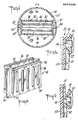
- lamp 10 has a metal/air battery 12, such as an aluminum/air battery, which includes a tank 14 containing a bath of electrolyte solution such as an aqueous saline (NaCI) solution, and an anode-cathode package 16 conveniently attached to a base 18, which is removably mountable upon the top of tank 14.
- Base 18 has a vent 20 for communication of air to the anode/cathode package as will be discussed below.
- a lamp member 22 is also supported on the base 18 and battery 12 by structure providing an electrical switch 24 (Figs. 6 and 7). The electrical switch 24 allows selective on-off connection between the battery and the lamp.
- the tank 14 is a unitary, electrically nonconductive body (e.g. a molded plastic element) having an inner wall defining a downwardly closed, upwardly open cylindrical volume which constitutes a single continuous reservoir for holding a body of the liquid electrolyte.
- the base 18 seats upon the upper rim of the tank to close the open top of this reservoir.
- the anode-cathode package 16 is secured to and depends from the base 18, so that when the base 18 is seated on the tank rim (in the position shown in Fig. 1), the anode-cathode package projects downwardly into the reservoir for contact of the anodes and cathodes of the package with electrolyte contained in the tank.
- the anode-cathode package 16 includes an electrically nonconductive frame 26.
- frame 26 has a pair of air cathodes C,C attached thereto in opposed, mutually spaced relationship. Any suitable air cathode known to those skilled in the art may be utilized.
- the frame in combination with the cathodes C,C forms a liquid-tight air chamber 30, to prevent entry of electrolyte fluid into the chamber.
- Air chamber 30 communicates with the ambient atmosphere through vent 20. It is desirable to avoid the entry of electrolyte fluid into the air chamber, because electrolyte if present therein could cause a short circuit between the cathodes.
- an electrically nonconductive baffle 32 may be disposed in the air chamber, if desired, to prevent any fluid that should happen to enter the air chamber from providing a current path between the cathodes.
- the baffle 32 may be constructed to any desired height; however, a preferred height of the baffle is between about one fourth and one half the height of the cathodes.
- a plurality of flanges 34 project from the frame 26 for attachment of metal anodes A,A thereto.
- the inclusion of the anodes in the package 16, supported by the flanges 34 allows the anodes and cathodes to be permanently positioned relative to each other in a convenient, unitized anode-cathode package, which may be readily replaced by a consumer when spent.
- each of the two cathodes C is a generally conventional air cathode 28 in the form of a rectangular sheetlike member having two opposed planar major surfaces, being constituted (for example) of two flat layers of an active carbon-hydrophobic polymer composition with a wire screen conductor 28a (Fig. 3) pressed between them.
- the frame 26 is a unitary, integral molded plastic element including a horizontal top portion mounted in the base 18; two vertical side portions depending from the top portion in facing spaced relation to each other; a bottom portion extending horizontally between the lower ends of the side portions; and the aforementioned flanges 34.
- Each of the air cathodes is mounted in the frame with its top edge secured to the frame top portion, its two vertical side edges respectively secured to the two frame side portions, and its lower edge secured to the frame bottom portions, in such manner that a continuous liquid-tight joint is provided between the cathode and frame around the entire periphery of the cathode.
- the two cathodes are disposed with their major surfaces oriented vertically in parallel relation to each other, such that one major surface of each cathode faces one major surface of the other cathode and is spaced therefrom by the frame side and bottom portions.
- These two last-mentioned cathode surfaces in cooperation with the frame side and bottom portions, cooperatively define the liquid-tight air chamber 30, and are exposed to air therein.
- the opposite major surfaces of the two cathodes, facing away from the air chamber are exposed to contact with electrolyte in the tank 14 when the package 16 is immersed therein. Owing to the substantially hydrophobic character of the cathodes, the aqueous electrolyte cannot penetrate the cathodes to enter the air chamber during such immersion.
- Each of the metal anodes A is a flat aluminum alloy plate 36 having opposed parallel major surfaces. Two such anodes (one for each cathode) are provided in the described battery. Each anode is disposed in the package 16, and held by the nonconductive flanges 34, with its major surfaces oriented vertically, such that one of the major anode surfaces is spaced from, facing, and parallel to the electrolyte-exposed major surface of one of the cathodes.
- the package 16 thus includes two anode-cathode pairs or cells, each comprising one anode and one cathode with parallel facing major surfaces defining an anode-cathode gap G between them.
- the reaction product is aluminum hydroxide, which forms copiously in an initially gel-like state.
- the anodes 36 may be constructed with one or more anode apertures 38 therethrough, allowing passage of electrolyte and reaction products through the anode. Electrolyte may also flow around the periphery of the anodes, thus insuring reaction product transport through many different flow paths. In this manner, reaction products can be transported away from the cathode region in the cell gap G in a more efficient manner and fresh electrolyte can replace the reaction products to ensure continuous production of electrical power.
- the apertures 38 be formed as a plurality of parallel elongated vertical slots in each anode. Apertures of this configuration and arrangement are especially effective in promoting egress of reaction product from, and sufficient electrolyte flow into and through, the anode- cathode gap to retard accumulation of reaction products therein.
- the cell gap may be in a range between about 1/16 and about one inch (a preferred gap being between about 1/16 and about 3/8 inch and a most preferred gap range being between about 1/8 and about 1/4 inch) without suffering undue shortening of useful operating time (between cleanings) because of accumulation of electrochemical reaction product in the cell gap.
- a common eletrolyte tank for a plurality of cells with a single common electrolyte reservoir that can be easily filled in a single pouring operation and readily cleaned after use of the battery.
- the convenient structure of the unitized anode-cathode package 16 allows simple slidable insertion of the package into the electrolyte tank, and easy slidable removal thereof for cleaning after use.
- Such a construction with a unitized anode and cathode- package 16 also allows selective replacement of the package when the anodes wear out; if desired, the entire anode and cathode package 16 may be replaced at once to provide fresh cathodes together with a new set of anodes.
- the invention contemplates the provision of means for engaging the tank with the electrode-carrying frame (when the frame is inserted into the tank) so as to divide the electrolyte reservoir into a plurality of separate and substantially electrically isolated electrolyte-holding zones, one for each anode-cathode pair or cell.
- this engaging means comprises a continuous rigid electrically conductive fin 40 formed integrally (e.g.
- the fin may simply abut the smooth tank wall 42, or, as shown, a continuous groove 44 may be formed in the tank side and bottom walls to receive the edge of the fin 40 along the entire length of the fin.
- a gasket may be mounted on the frame or the tank inner wall to provide engagement between the tank and frame; one form of gasket, usable with the fin 40 and grooves 44, is shown at 46 in Fig. 5, mounted in a groove 44 defined by the tank interior surface for engaging the fin edge when the fin is inserted in that groove.
- This or other forms of gasket may be secured (to the tank or to the frame, as the case may be) in any suitable manner, e.g. with an adhesive.
- a rigid fin similar to fin 40 may be formed on and project from the tank inner side and bottom walls to engage the surface of the frame or to be received within a groove formed in the frame surface.
- Another -alternative embodiment is to provide a frame so shaped and dimensioned that the peripheral surface of its side and bottom portions engages directly with the inner wall 42 of the tank 14, or any other construction (e.g., a flexible blade or bead, carried by the frame) that segregates the common electrolyte tank into different zones to inhibit electrolytic shunting between anodes.
- the illustrated battery also includes circuit means 48 (carried by the base 18) connecting the two anode- cathode pairs of cells in series with each other and with an external load represented by a light bulb B , with switch 24 also included in the circuit. That is to say, the anode of one anode-cathode pair or cell is connected to the cathode of the other pair or cell, and the bulb B and switch 24 are connected in series between the remaining cathode (of the first-mentioned cell) and anode (of the other cell).
- the illustrated lamp 10 can be stored indefinitely with the base 18 seated on the tank 14, so long as the tank is empty (i.e., contains no electrolyte), without any deterioration of the electrodes or other elements.
- the base is removed from the tank, together with the anode-cathode package 16 attached to the base; the single reservoir defined by the tank is filled with aqueous NaCl solution, as electrolyte, to a suitable level; and the package 16 is inserted in the electrolyte-containing reservoir until the base seats on the tank rim.
- both cells of the battery now generate electric current, with a combined voltage sufficient to illuminate the bulb B upon closure of the switch 24.
- the engagement of fin 40 with the wall 42 of tank 14 divides the single common electrolyte reservoir into two separate electrolyte-holding zones 49a and 49b (Fig. 4), each containing one of the anodes 36 and the air cathode surface facing that anode.
- These two zones 49a and 49b are substantially electrically isolated from each other, because even if there is some slight leakage around the fin edge, the engagement between the fin and wall (which engagement is essentially continuous around the entire boundary between the two zones, within the reservoir volume occupied by electrolyte) so greatly attenuates any electric current flow path through the electrolyte between the zones that little if any anode-to-anode shunting can occur through the electrolyte. Thus, impairment of cell efficiency by such shunting is prevented.
- the provision of fin-receiving grooves and/or gaskets contributes to the desired attenuation or elimination of zone-to-zone current flow paths at the boundary between zones.
- each zone 49a or 49b there is a relatively large electrolyte volume external to the anode-cathode gap therein, and the anode major surface facing away from the anode-cathode gap is exposed to this external volume. Consequently, the slots 38 formed in each anode provide passages for egress of reaction product from the anode-cathode gap to the external volume of electrolyte as the cell operation proceeds, the shape and orientation of the slots being especially conducive to such egress. The accumulation of reaction product within the anode-cathode gaps is thereby retarded, even though the gaps may be made relatively narrow for reasons of cell efficiency.
- the caustic formed adjacent the electrolyte-exposed cathode surface initially inhibits formation of gel-like aluminum hydroxide reaction product in the gap, and contributes to the retardation of reaction product accumulation between anode and cathode.
- the base 18 with the attached package 16 are removed from the tank 14; and the tank reservoir is emptied of electrolyte and washed, as is the anode-cathode package.
- switch device 24 incorporated in the circuit means of the illustrated lamp.
- This switch 24 allows sliding motion of the lamp member 22 up and down the contacts of the switch, electrical connection being established when the member 22 is raised to its uppermost position away from the base 18 and being interrupted when the member 22 is translated downwardly towards the base 18.
- the switch 24 includes a cartridge portion of member 22, which carries the bulb B and bears a pair of electrically nonconductive slider projections or lugs 54 respectively formed on opposite side surfaces of the cartridge.
- a pair of electrical contacts 56 are electrically connected to the bulb B and respectively project through and slightly beyond the lugs 54.
- the structure also includes a pair of stiffly resilient channel-defining electrically nonconductive arms 50 formed integrally with and extending upwardly from the base 18 in spaced and, when unstressed, substantially parallel relation to each other with their channels opening toward each other and with the cartridge disposed between them, so that the lugs 54 respectively engage channel-leg-defining portions of the arms 50; the contacts 56 respectively project into the channels of the arms, and the cartridge forces the arms apart divergently from their unstressed positions.
- a stop 51 at the top of each arm limits upward travel of the lugs.
- a pair of flat metal conductor strips 52 are connected in the circuit 48 and respectively extend within the channels of the arms 50; each channel has a lower portion sufficiently deep to hold the contact 56 projecting therein away from the conductor 52 extending therein, and an upper portion sufficiently shallow to permit engagement of the last-mentioned contact and conductor, such that upward movement of the cartridge relative- to the arms permits the arms to converge resiliently, completing an electric circuit through the battery and the load when the lugs reach the upper portions of the arms (Fig. 6), and such that downward movement of the cartridge-relative to the arms causes the arms to diverge, opening the circuit when the lugs reach the lower portions of the arms (Fig. 7).
- the arms 50 cooperatively grip and retain the cartridge of lamp member 22 between them at any vertical position to which the cartridge is moved, because they are resilient and outwardly deformed by the cartridge.
- the conductors 52 lie flat in the bases of the channels of these arms.
- the lugs 54 interferingly engage, and ride on, the edges of the legs or sides of the channels. In the lower portions of the arms 52, where the channels are relatively deep, the interfering engagement between legs and lugs holds the contacts 56 away from the conductors as shown in Fig.
- the contacts can engage the conductors, and when the cartridge is moved to these upper portions of the arms, the resilient bias of the arms urges the arms inwardly, bringing the conductors into such engagement with the contacts, as indicated in Fig. 6.
- a battery in accordance with the invention may be provided with more than two cells by, for example, affixing more than two air cathodes 28 to the frame 26, with the cathodes sharing one or more common air chambers; providing a corresponding anode for each cathode; and configuring the frame 26 to segregate the tank 14 into a plurality of separate cell zones for each anode-cathode pair.
- the described apertured anode construction may be utilized in any type of metal/air cell and the feature of a single electrolyte tank segregated into separate cell zones by a frame engaged therewith may be utilized with anodes or air cathodes of various constructions including anodes without apertures.
- the switch 24 may also be used in other environments.
Landscapes
- Engineering & Computer Science (AREA)
- General Engineering & Computer Science (AREA)
- Manufacturing & Machinery (AREA)
- Chemical & Material Sciences (AREA)
- Chemical Kinetics & Catalysis (AREA)
- Electrochemistry (AREA)
- General Chemical & Material Sciences (AREA)
- Hybrid Cells (AREA)
- Dc-Dc Converters (AREA)
Applications Claiming Priority (2)
| Application Number | Priority Date | Filing Date | Title |
|---|---|---|---|
| US06/798,988 US4626482A (en) | 1985-11-18 | 1985-11-18 | Metal/air batteries |
| US798988 | 1985-11-18 |
Publications (2)
| Publication Number | Publication Date |
|---|---|
| EP0227289A2 true EP0227289A2 (fr) | 1987-07-01 |
| EP0227289A3 EP0227289A3 (fr) | 1988-03-23 |
Family
ID=25174767
Family Applications (1)
| Application Number | Title | Priority Date | Filing Date |
|---|---|---|---|
| EP86308872A Withdrawn EP0227289A3 (fr) | 1985-11-18 | 1986-11-13 | Batteries métal-air |
Country Status (6)
| Country | Link |
|---|---|
| US (1) | US4626482A (fr) |
| EP (1) | EP0227289A3 (fr) |
| JP (1) | JPS62177873A (fr) |
| CN (1) | CN1011101B (fr) |
| AU (1) | AU579306B2 (fr) |
| CA (1) | CA1286715C (fr) |
Cited By (4)
| Publication number | Priority date | Publication date | Assignee | Title |
|---|---|---|---|---|
| EP0298690A1 (fr) * | 1987-07-06 | 1989-01-11 | Alcan International Limited | Cathodes à air et matériaux pour ces cathodes |
| EP0265242A3 (fr) * | 1986-10-22 | 1990-04-18 | Alcan International Limited | Batterie multicellulaire du type métal-air |
| EP0417324A4 (en) * | 1989-04-04 | 1992-03-25 | Koa Oil Company, Limited | Air cell |
| WO1992010864A3 (fr) * | 1990-12-12 | 1993-04-01 | Rolls Royce & Ass | Configurations de batteries a metal/oxygene |
Families Citing this family (60)
| Publication number | Priority date | Publication date | Assignee | Title |
|---|---|---|---|---|
| US4745529A (en) * | 1986-10-06 | 1988-05-17 | Alupower, Inc. | Battery powered light source |
| EP0316113A3 (fr) * | 1987-11-09 | 1990-03-28 | Alcan International Limited | Batterie métal-air avec insufflation pulsatoire de gaz |
| US4925744A (en) * | 1989-04-07 | 1990-05-15 | Eltech Systems Corporation | Primary aluminum-air battery |
| US4988581A (en) * | 1989-07-19 | 1991-01-29 | Alcan International Limited | Metal-air bipolar cell unit |
| US5206576A (en) * | 1989-11-22 | 1993-04-27 | Motorola, Inc. | Battery charger |
| US5413881A (en) * | 1993-01-04 | 1995-05-09 | Clark University | Aluminum and sulfur electrochemical batteries and cells |
| US5571600A (en) * | 1994-11-07 | 1996-11-05 | Clark University | Sulfur/aluminum electrochemical batteries |
| US5569551A (en) * | 1995-04-24 | 1996-10-29 | Aer Energy Resources Inc. | Dual air elecrtrode cell |
| DE19537683C2 (de) * | 1995-10-10 | 1998-04-16 | Stn Atlas Elektronik Gmbh | Außenluftunabhängiger Speicher für elektrische Energie |
| US5639568A (en) * | 1995-10-16 | 1997-06-17 | Aer Energy Resources, Inc. | Split anode for a dual air electrode cell |
| US5919582A (en) * | 1995-10-18 | 1999-07-06 | Aer Energy Resources, Inc. | Diffusion controlled air vent and recirculation air manager for a metal-air battery |
| US5691074A (en) * | 1995-10-18 | 1997-11-25 | Aer Energy Resources, Inc. | Diffusion controlled air vent for a metal-air battery |
| RU2102822C1 (ru) * | 1995-11-13 | 1998-01-20 | Товарищество с ограниченной ответственностью Научно-производственная фирма "Рико" | Металловоздушный химический источник тока |
| RU2127932C1 (ru) * | 1996-09-30 | 1999-03-20 | Научно-производственный комплекс источников тока "Альтэн" | Воздушно-алюминиевый элемент, батарея на основе воздушно-алюминиевого элемента и способ эксплуатации батареи |
| US6106962A (en) * | 1997-09-24 | 2000-08-22 | Aer Energy Resources Inc. | Air manager control using cell voltage as auto-reference |
| US6239508B1 (en) | 1997-10-06 | 2001-05-29 | Reveo, Inc. | Electrical power generation system having means for managing the discharging and recharging of metal fuel contained within a network of metal-air fuel cell battery subsystems |
| US6296960B1 (en) | 1997-10-06 | 2001-10-02 | Reveo, Inc. | System and method for producing electrical power using metal-air fuel cell battery technology |
| US6335111B1 (en) | 1997-10-06 | 2002-01-01 | Reveo, Inc. | Metal-air fuel cell battery system employing a plurality of moving cathode structures for improved volumetric power density |
| US6228519B1 (en) | 1997-10-06 | 2001-05-08 | Reveo, Inc. | Metal-air fuel cell battery systems having mechanism for extending the path length of metal-fuel tape during discharging and recharging modes of operation |
| US6558829B1 (en) | 1997-10-06 | 2003-05-06 | Reveo, Inc. | Appliance with refuelable and rechargeable metal-air fuel cell battery power supply unit integrated therein |
| US6348277B1 (en) | 1997-10-06 | 2002-02-19 | Reveo, Inc. | Method of and system for producing and supplying electrical power to an electrical power consuming device using a metal-air fuel cell battery (FCB) module and a supply of metal-fuel cards |
| US6299997B1 (en) | 1997-10-06 | 2001-10-09 | Reveo, Inc. | Ionically-conductive belt structure for use in a metal-air fuel cell battery system and method of fabricating the same |
| US6472093B2 (en) | 1997-10-06 | 2002-10-29 | Reveo, Inc. | Metal-air fuel cell battery systems having a metal-fuel card storage cartridge, insertable within a fuel cartridge insertion port, containing a supply of substantially planar discrete metal-fuel cards, and fuel card transport mechanisms therein |
| US6287715B1 (en) | 1997-10-06 | 2001-09-11 | Reveo, Inc. | Metal-air fuel cell battery system having means for controlling discharging and recharging parameters for improved operating efficiency |
| US6569555B1 (en) | 1997-10-06 | 2003-05-27 | Reveo, Inc. | Refuelable and rechargeable metal-air fuel cell battery power supply unit for integration into an appliance |
| US6451463B1 (en) | 1997-10-06 | 2002-09-17 | Reveo, Inc. | Electro-chemical power generation systems employing arrays of electronically-controllable discharging and/or recharging cells within a unity support structure |
| US6306534B1 (en) | 1997-10-06 | 2001-10-23 | Reveo, Inc. | Metal-air fuel cell battery systems employing means for discharging and recharging metal-fuel cards |
| US6641943B1 (en) | 1997-10-06 | 2003-11-04 | Reveo, Inc. | Metal-air fuel cell battery system having means for recording and reading operating parameters during discharging and recharging modes of operation |
| US6087029A (en) * | 1998-01-06 | 2000-07-11 | Aer Energy Resources, Inc. | Water recovery using a bi-directional air exchanger for a metal-air battery |
| US6436571B1 (en) * | 1998-03-06 | 2002-08-20 | Rayovac Corporation | Bottom seals in air depolarized electrochemical cells |
| US6274261B1 (en) | 1998-12-18 | 2001-08-14 | Aer Energy Resources, Inc. | Cylindrical metal-air battery with a cylindrical peripheral air cathode |
| US6475658B1 (en) | 1998-12-18 | 2002-11-05 | Aer Energy Resources, Inc. | Air manager systems for batteries utilizing a diaphragm or bellows |
| US6299998B1 (en) | 1999-03-15 | 2001-10-09 | Reveo, Inc. | Movable anode fuel cell battery |
| RU2168811C2 (ru) * | 1999-05-06 | 2001-06-10 | Пашков Игорь Николаевич | Источник тока, способ изготовления его анода и материал для изготовления активной части анода |
| US6368751B1 (en) | 1999-10-08 | 2002-04-09 | Reves, Inc. | Electrochemical electrode for fuel cell |
| US6653003B1 (en) | 1999-10-12 | 2003-11-25 | Reveo Inc. | Fuel cell support and electrical interconnector |
| US6421561B1 (en) * | 1999-12-30 | 2002-07-16 | Birch Point Medical, Inc. | Rate adjustable drug delivery system |
| US6558825B1 (en) | 2000-05-12 | 2003-05-06 | Reveo, Inc. | Fuel containment and recycling system |
| US6759159B1 (en) | 2000-06-14 | 2004-07-06 | The Gillette Company | Synthetic jet for admitting and expelling reactant air |
| US6869710B2 (en) * | 2001-02-09 | 2005-03-22 | Evionyx, Inc. | Metal air cell system |
| EP1386372A2 (fr) * | 2001-02-09 | 2004-02-04 | Evionyx, Inc. | Systeme de piles metalliques a depolarisation par l'air |
| US6800393B2 (en) | 2001-05-14 | 2004-10-05 | Reveo, Inc. | Metal air cell incorporating ionic isolation systems |
| RU2183371C1 (ru) * | 2001-06-07 | 2002-06-10 | Серопян Михаил Георгиевич | Металловоздушная батарея |
| RU2199801C1 (ru) * | 2001-11-19 | 2003-02-27 | Груздев Александр Иванович | Металловоздушный источник тока |
| US20060108226A1 (en) * | 2002-11-05 | 2006-05-25 | Stefan Wolz | Method for producing fully ceramic tooth elements having a pre-determined spatial form by means of electrophoresis |
| TWI280677B (en) * | 2003-02-18 | 2007-05-01 | Sony Chemicals & Information D | Liquid absorbing sheet and nonaqueous electrolyte battery pack |
| DE102006015537A1 (de) * | 2006-03-31 | 2007-10-11 | Neos International Gmbh | Elektrochemische Spannungs-/Stromquelle, insbesondere Brennstoffzelle oder Batterie |
| WO2007112912A1 (fr) * | 2006-03-31 | 2007-10-11 | Neos International Gmbh | Circuit de sécurité d'un élément de batterie |
| US7943259B1 (en) | 2006-12-18 | 2011-05-17 | University Of South Florida | Method of controlled delivery for use of electrochemical power source |
| CN101882685B (zh) * | 2010-03-31 | 2012-07-04 | 孙公权 | 一种用于海水水下的镁氧电池 |
| TWI418079B (zh) * | 2011-07-04 | 2013-12-01 | Delta Electronics Inc | 電池模組 |
| TWI508354B (zh) | 2012-04-04 | 2015-11-11 | Nissan Motor | Air battery |
| JP6187748B2 (ja) * | 2013-06-05 | 2017-08-30 | 日産自動車株式会社 | 空気電池システム |
| PH12015000053A1 (en) * | 2015-02-13 | 2016-08-22 | Mijeno Aisa | A lamp device |
| KR102575868B1 (ko) | 2016-01-14 | 2023-09-06 | 후지쿠라 컴퍼지트 가부시키가이샤 | 금속 공기 전지 유닛 및 금속 공기 전지 |
| CN107615569B (zh) | 2016-03-01 | 2020-03-24 | 藤仓橡胶工业株式会社 | 金属空气电池 |
| RU169334U1 (ru) * | 2016-10-07 | 2017-03-15 | Федеральное государственное бюджетное учреждение науки Объединенный институт высоких температур Российской академии наук (ОИВТ РАН) | Металло-воздушный электрохимический элемент |
| JP6715354B2 (ja) | 2017-02-03 | 2020-07-01 | 藤倉コンポジット株式会社 | 金属空気電池、及びその使用方法 |
| RU2710024C1 (ru) * | 2018-10-29 | 2019-12-24 | Федеральное государственное казенное военное образовательное учреждение высшего образования "ВОЕННАЯ АКАДЕМИЯ МАТЕРИАЛЬНО-ТЕХНИЧЕСКОГО ОБЕСПЕЧЕНИЯ имени генерала армии А.В. Хрулева" | Металловодяная батарея |
| CN109827090B (zh) * | 2019-01-21 | 2024-04-05 | 生迪光电科技股份有限公司 | 照明装置 |
Family Cites Families (11)
| Publication number | Priority date | Publication date | Assignee | Title |
|---|---|---|---|---|
| US2724010A (en) * | 1953-09-21 | 1955-11-15 | Union Carbide & Carbon Corp | Air-depolarized cell |
| US3193413A (en) * | 1961-07-12 | 1965-07-06 | Pentti J Tamminen | Method for activating and isolating a galvanic battery and galvanic battery produced according to said method |
| US3372271A (en) * | 1965-09-24 | 1968-03-05 | Union Carbide Australia | Battery-operated light |
| US3403249A (en) * | 1965-12-22 | 1968-09-24 | Union Carbide Corp | Battery powered signal unit |
| US3519812A (en) * | 1968-02-29 | 1970-07-07 | Union Carbide Corp | Portable electric lantern with swivel-type lamp assembly |
| US3682706A (en) * | 1970-06-18 | 1972-08-08 | Michel N Yardney | Gas depolarized cell |
| FR2126101B1 (fr) * | 1971-02-25 | 1975-02-21 | Wonder | |
| JPS5850615Y2 (ja) * | 1977-04-04 | 1983-11-17 | 古河電池株式会社 | 浮遊式金属−空気電池 |
| US4275125A (en) * | 1980-03-03 | 1981-06-23 | Universal Fuel Systems, Inc. | Fuel cell |
| EP0047792B1 (fr) * | 1980-09-12 | 1988-12-14 | Dst Sa | Batterie, cellule électrochimique dépolarisée par un gaz et élément bipolaire pour la batterie |
| US4389466A (en) * | 1981-06-03 | 1983-06-21 | The United States Of America As Represented By The United States Department Of Energy | Rapidly refuelable fuel cell |
-
1985
- 1985-11-18 US US06/798,988 patent/US4626482A/en not_active Expired - Fee Related
-
1986
- 1986-11-10 AU AU64987/86A patent/AU579306B2/en not_active Ceased
- 1986-11-10 CA CA000522601A patent/CA1286715C/fr not_active Expired - Fee Related
- 1986-11-13 EP EP86308872A patent/EP0227289A3/fr not_active Withdrawn
- 1986-11-18 JP JP61275092A patent/JPS62177873A/ja active Pending
- 1986-11-18 CN CN86107892A patent/CN1011101B/zh not_active Expired
Cited By (5)
| Publication number | Priority date | Publication date | Assignee | Title |
|---|---|---|---|---|
| EP0265242A3 (fr) * | 1986-10-22 | 1990-04-18 | Alcan International Limited | Batterie multicellulaire du type métal-air |
| EP0298690A1 (fr) * | 1987-07-06 | 1989-01-11 | Alcan International Limited | Cathodes à air et matériaux pour ces cathodes |
| EP0417324A4 (en) * | 1989-04-04 | 1992-03-25 | Koa Oil Company, Limited | Air cell |
| US5240785A (en) * | 1989-04-04 | 1993-08-31 | Koa Oil Company, Limited | Air cell |
| WO1992010864A3 (fr) * | 1990-12-12 | 1993-04-01 | Rolls Royce & Ass | Configurations de batteries a metal/oxygene |
Also Published As
| Publication number | Publication date |
|---|---|
| JPS62177873A (ja) | 1987-08-04 |
| AU579306B2 (en) | 1988-11-17 |
| AU6498786A (en) | 1987-05-21 |
| CN1011101B (zh) | 1991-01-02 |
| US4626482A (en) | 1986-12-02 |
| CA1286715C (fr) | 1991-07-23 |
| CN86107892A (zh) | 1987-09-16 |
| EP0227289A3 (fr) | 1988-03-23 |
Similar Documents
| Publication | Publication Date | Title |
|---|---|---|
| US4626482A (en) | Metal/air batteries | |
| US5462816A (en) | Air cell | |
| US4871627A (en) | Multi-cell metal/air battery | |
| AU614922B2 (en) | Primary aluminum-air battery | |
| US6630262B2 (en) | Metal-gas cell battery with soft pocket | |
| US4490443A (en) | Battery having electrolyte supply reservoir and activation tank disposed in a battery housing | |
| EP0694215A4 (fr) | Element electrochimique a anode en zinc | |
| US4745529A (en) | Battery powered light source | |
| US5049457A (en) | Electrolyte for an aluminum air-battery comprising an anti-foaming agent and corrosion exhibitor | |
| EP0068183B1 (fr) | Cellule électrochimique étanche | |
| DE69901116D1 (de) | Elektrochemische zelle mit vergrösserter anoden-kathoden-grenzfläche | |
| US5225291A (en) | Deferred actuated battery assembly | |
| EP0417324A1 (fr) | Batterie a air | |
| US20010009735A1 (en) | Metal-gas cell battery with soft pocket | |
| GB2023918A (en) | Galvanic cell | |
| US4507370A (en) | Miniature galvanic cell construction providing gas channels between electrode compartments | |
| US5389457A (en) | Gas filled collapsible member within anode to accommodate expansion of anode | |
| RU2127932C1 (ru) | Воздушно-алюминиевый элемент, батарея на основе воздушно-алюминиевого элемента и способ эксплуатации батареи | |
| US3811955A (en) | High discharge rate mercury cell | |
| RU1801233C (ru) | Воздушно-металлическа электрохимическа батаре | |
| US4442186A (en) | Porous annulus providing gas channels between electrode compartments | |
| KR200319220Y1 (ko) | 등 부표용 축전지 | |
| RU2304828C1 (ru) | Герметичный никель-кадмиевый аккумулятор | |
| KR960002927A (ko) | 밀폐형 알칼리 아연 2차 전지 | |
| WO2004038827A2 (fr) | Structure de connexion electrique et de joint liquide |
Legal Events
| Date | Code | Title | Description |
|---|---|---|---|
| PUAI | Public reference made under article 153(3) epc to a published international application that has entered the european phase |
Free format text: ORIGINAL CODE: 0009012 |
|
| AK | Designated contracting states |
Kind code of ref document: A2 Designated state(s): CH DE FR GB IT LI SE |
|
| PUAL | Search report despatched |
Free format text: ORIGINAL CODE: 0009013 |
|
| RIN1 | Information on inventor provided before grant (corrected) |
Inventor name: HALEN, ROBERT P. Inventor name: CONNOLLY, PETER F. |
|
| AK | Designated contracting states |
Kind code of ref document: A3 Designated state(s): CH DE FR GB IT LI SE |
|
| 17P | Request for examination filed |
Effective date: 19880919 |
|
| 17Q | First examination report despatched |
Effective date: 19900426 |
|
| STAA | Information on the status of an ep patent application or granted ep patent |
Free format text: STATUS: THE APPLICATION HAS BEEN WITHDRAWN |
|
| 18W | Application withdrawn |
Withdrawal date: 19910515 |
|
| R18W | Application withdrawn (corrected) |
Effective date: 19910515 |
|
| RIN1 | Information on inventor provided before grant (corrected) |
Inventor name: HALEN, ROBERT P. Inventor name: CONNOLLY, PETER F. |