EP0227368A2 - Pistolet de pulvérisation de poudre à jet en éventail réglable - Google Patents
Pistolet de pulvérisation de poudre à jet en éventail réglable Download PDFInfo
- Publication number
- EP0227368A2 EP0227368A2 EP86309542A EP86309542A EP0227368A2 EP 0227368 A2 EP0227368 A2 EP 0227368A2 EP 86309542 A EP86309542 A EP 86309542A EP 86309542 A EP86309542 A EP 86309542A EP 0227368 A2 EP0227368 A2 EP 0227368A2
- Authority
- EP
- European Patent Office
- Prior art keywords
- nozzle
- orifice
- powder
- pattern
- width
- Prior art date
- Legal status (The legal status is an assumption and is not a legal conclusion. Google has not performed a legal analysis and makes no representation as to the accuracy of the status listed.)
- Withdrawn
Links
Images
Classifications
-
- B—PERFORMING OPERATIONS; TRANSPORTING
- B05—SPRAYING OR ATOMISING IN GENERAL; APPLYING FLUENT MATERIALS TO SURFACES, IN GENERAL
- B05B—SPRAYING APPARATUS; ATOMISING APPARATUS; NOZZLES
- B05B1/00—Nozzles, spray heads or other outlets, with or without auxiliary devices such as valves, heating means
- B05B1/30—Nozzles, spray heads or other outlets, with or without auxiliary devices such as valves, heating means designed to control volume of flow, e.g. with adjustable passages
- B05B1/32—Nozzles, spray heads or other outlets, with or without auxiliary devices such as valves, heating means designed to control volume of flow, e.g. with adjustable passages in which a valve member forms part of the outlet opening
- B05B1/326—Gate valves; Sliding valves; Cocks
-
- B—PERFORMING OPERATIONS; TRANSPORTING
- B05—SPRAYING OR ATOMISING IN GENERAL; APPLYING FLUENT MATERIALS TO SURFACES, IN GENERAL
- B05B—SPRAYING APPARATUS; ATOMISING APPARATUS; NOZZLES
- B05B1/00—Nozzles, spray heads or other outlets, with or without auxiliary devices such as valves, heating means
- B05B1/02—Nozzles, spray heads or other outlets, with or without auxiliary devices such as valves, heating means designed to produce a jet, spray, or other discharge of particular shape or nature, e.g. in single drops, or having an outlet of particular shape
- B05B1/04—Nozzles, spray heads or other outlets, with or without auxiliary devices such as valves, heating means designed to produce a jet, spray, or other discharge of particular shape or nature, e.g. in single drops, or having an outlet of particular shape in flat form, e.g. fan-like, sheet-like
- B05B1/042—Outlets having two planes of symmetry perpendicular to each other, one of them defining the plane of the jet
-
- B—PERFORMING OPERATIONS; TRANSPORTING
- B05—SPRAYING OR ATOMISING IN GENERAL; APPLYING FLUENT MATERIALS TO SURFACES, IN GENERAL
- B05B—SPRAYING APPARATUS; ATOMISING APPARATUS; NOZZLES
- B05B5/00—Electrostatic spraying apparatus; Spraying apparatus with means for charging the spray electrically; Apparatus for spraying liquids or other fluent materials by other electric means
- B05B5/025—Discharge apparatus, e.g. electrostatic spray guns
- B05B5/03—Discharge apparatus, e.g. electrostatic spray guns characterised by the use of gas, e.g. electrostatically assisted pneumatic spraying
- B05B5/032—Discharge apparatus, e.g. electrostatic spray guns characterised by the use of gas, e.g. electrostatically assisted pneumatic spraying for spraying particulate materials
Definitions
- This invention relates to electrostatic powder spray systems and more particularly to powder spray guns for use in such systems.
- Electrostatic powder spray systems operate on the principle of transporting a finely divided powder, generally on the order of 150 mesh, to a spray gun or spray head while the powder is entrained in an air or gaseous stream.
- the air entrained powder is transferred from the nozzle of the gun to a target article or substrate by an electrostatic charge applied to the powder and an effectively opposite charge on the substrate.
- the powder is generally heated and melted so as to adhere the powder to the substrate as a film when the molten powder subsequently cools.
- a characteristic of nearly all electrostatic powder spray applications is that less than half of all the sprayed powder adheres to the target article or substrate.
- the oversprayed powder thus must generally be collected, cleaned, and recycled in order for a powder spray system to operate efficiently and economically.
- the cost of collecting and recycling the powder is substantially greater than the cost of initially applying the powder. Consequently, it is very important to the economy of powder spray systems that as high a percentage as possible of the initial sprayed powder be adhered to the target article or substrate so that a minimum of the sprayed powder need by recycled or lost if the powder is not to be recycled.
- the efficiency or percentage of sprayed powder which adheres to the target is a function of many variables, including the size and density of the sprayed powder, the velocity of the air stream in which the powder is ejected from the spray gun, the charge applied to the powder, and the configuration of the powder spray pattern.
- the number of applications in which the amount of oversprayed powder can be optimally minimized is dependent on the variety and number of nozzles available to define the spray pattern and to focus the powder spray. It is therefore still another objective of this invention to provide an electrostatic powder spray gun which has a nozzle adjustable continuously to vary the powder spray pattern or continuously vary the focus of the powder spray over a given range.
- a powder spray gun in accordance with the invention in which the nozzle is adjustable so as to change the geometry of the nozzle orifice to control the pattern of powder spray.
- the adjustability of the nozzle is achieved by providing a nozzle having a fixed orifice in relation to which is adjustably positioned a sleeve or other orifice restricting element with a pair of edges which can be simultaneously moved across the nozzle orifice as the element is rotated to vary the effective boundary of the nozzle opening to shape the pattern and focus the powder spray.
- Electrostatic powder spray guns often employ flat spray nozzles producing flat fan patterns. Minimizing the amount of overspray has heretofore required selection of a nozzle which produces a pattern with a width only sufficient to encompass the work.
- the fan pattern is achieved through the use of a slotted nozzle with the width of the slot determining the width of the fan pattern.
- the width of the fan spray pattern is also varied.
- An advantage of the present invention is that it provides a powder spray gun which, with a single nozzle, will direct powder spray patterns with widths which vary over a wide range.
- the spray pattern is continuously adjustable to any width over a 9 to 1 range.
- the primary advantage of a gun in accordance with the invention is the ease with which it facilitates adjustment of the powder spray pattern of an electrostatic powder gun without change of the gun nozzle.
- the powder spray gun of this invention is intended for use as a part of a powder spray system, such as that disclosed in United States Patent No. 4,245,551.
- air entrained powder is supplied to a powder spray gun through a supply hose while simultaneously, a very high voltage electrical charge is supplied to the gun from a source of electrical power.
- the electrostatic spray gun is operative to dispense the air entrained powder in a predetermined pattern while simultaneously applying a charge to the powder.
- the electrical charge then is operative to transport the powder from the nozzle of the gun to a target article or substrate which is of an opposite charge from that applied to the powder by the gun.
- a negative charge is applied to the powder by the electrostatic spray gun and the target article or substrate to which the powder is to be applied is grounded so that the powder is attracted to the article and adheres thereto as a consequence of the charge on the powder.
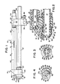
- FIG. 1 there is illustrated an embodiment of a powder spray gun 10 incorporating the invention of this application.
- This powder spray gun comprises a housing 11 upon which there is mounted a nozzle 12 and an electrode support 13.
- the housing 11 comprises a pair of spaced mounting blocks 14 and 15 between which there are supported a pair of tubes 16 and 17.
- the uppermost one of these tubes is a resistor support tube 16 and the lowermost tube is a powder transport tube 17.
- Components 14, 16 and 17 are electrically nonconductive, while component 15 is electrically conductive to provide conductance to ground.
- the forwardmost one of the mounting blocks 14 has a lower through-bore 20 therein which may be threaded and an upper blind recess 21 as is illustrated more fully in Figure 2.
- the blind recess 21 is threaded as indicated at 22. Intersecting this blind recess 21 there is an angled threaded bore 23.
- the electrode support 13 is threaded into the bore 23 and the forward threaded end 24 of the resistor support tube 16 is threaded into the threaded section 22 of the recess 21.
- the threaded forward end 25 of the powder transport tube 17 is threaded into and through the threaded bore 20 of the mounting block 14 so that the forwardmost end 25 of the powder transport tube 17 extends forwardly beyond the front face 26 of the mounting block 14.
- the nozzle 12 which is a conventional slotted nozzle, is threaded onto this forwardmost end 25 of the powder transport tube 17.
- the powder transport tube 17 is locked to the mounting block 14 by a jam nut 27 threaded over the rearwardmost threaded portion of the threaded forward end 25 of the powder transport tube 17.
- the rear mounting block 15 is provided with a pair of through-bores 30, 31.
- the powder transport tube 17 extends through the lowermost one of these through-bores.
- the uppermost bore 31 is threaded for reception of the threaded rear end of the resistor support tube 16 and for reception of the threaded forward end 33 of a cable adapter 34.
- the rear end of the cable adapter 34 is also threaded for connection to a conventional electrical shielded cable (not shown).
- transverse bore 36 Extending transversely through the rear mounting block 13 there is a transverse bore 36.
- This transverse bore 36 is intersected by a threaded bore 37 within which there is a set screw 38.
- the transverse bore 36 enables the rear mounting block 15 and thus the gun 10 to be secured to a mounting rod and fixed thereon by the set screw 38 as is conventional in this art.
- this resistor 40 is connected via an electrically conductive spring 41 to an insulated electrical cable 42 contained internally of a conventional shielded cable (not shown) adapted to be connected to the cable adapter 34.
- the forward end of the resistor 40 is electrically connected to a smaller resistor 44 contained internally of the electrically non-conductive casing the electrode support 13.
- This small resistor 44 is connected via a conventional connector 45 to the forward end of the large resistor 40.
- the small resistor 44 is attached to the powder charging electrode 46 which extends forwardly beyond the forward end of the casing of electrode support 13.
- the illustrated placement of the electrode is only one of many. Such electrodes are, for example, also alternatively disposed within the nozzle of the gun.
- a source of air entrained powder such as a conventional powder feed hopper
- a source of air entrained powder such as a conventional powder feed hopper
- air entrained powder may be transported through the tube and ejected from an orifice 49 in the forward end of the nozzle 12.
- the nozzle 12 is a conventional slotted nozzle which is a type which will more fully benefit by this invention.
- any type of powder spray nozzle may be utilized in the practice of this invention as long as the width of the spray pattern is determined by the effective position of the boundary of the nozzle orifice.
- the powder ejected from the nozzle orifice 49 is electrically charged during the course of passage through an electrostatic field created by the electrode 46. That powder then adheres to an effectively oppositely charged substrate (not shown) toward which the powder is ejected.
- the nozzle 12 has an outer surface which includes a cylindrical portion 52, a truncated conical portion 53 forward of the cylindrical portion 52, and a circular planar end portion 54, the axes of the three portions being the same.
- the orifice 49 of the nozzle 12 is an elongated rectangular slot centered on the diagonal of the circular end 54 of the nozzle 12, and extending onto and terminating on the conical portion 53 of the surface of the nozzle 12.
- the powder sprayed from a nozzle of this type would be effected in a wide fan pattern, the width of the pattern being determined by the position of the slot ends 55.
- the pattern of the powder ejected from the nozzle of the gun be sufficiently wide to encompass the entire work to be coated, but no wider than necessary to do so. Due to a substitution of workpieces of different sizes, or due to some other change of parameters, it may become necessary to widen or narrow the spray pattern to maintain the optimum efficiency in coating the work piece.
- the illustrated embodiment of the invention is provided with a sleeve 61 rotatably attached to the outer surface of the nozzle 12.
- the sleeve 61 includes a cylindrical portion 62 which fits in close conformity with the cylindrical portion 52 of the outer surface of the nozzle 12, and a truncated conical portion 63 which fits in close conformity with the conical portion 53 of the outer surface of the nozzle 12.
- the forward edge 64 of the sleeve 61 which is the smaller end of the conical portion 63 of the sleeve 61, is in the plane of the circular end 53 of the nozzle 12.
- the rotatably mounted sleeve 61 is dimensioned so as to be retained on the nozzle 12 by friction.
- An O-ring seal 66 is set in an annular groove 67 in the cylindrical portion 52 of the outer surface of the nozzle 12.
- the sleeve 61 is shown positioned on the nozzle 12.
- a hole 72 which is shaped so that the sleeve partially blocks the orifice 49 of the nozzle 12 to differing degrees depending on the angular position of the sleeve 61 on the nozzle 12.
- the hole 72 is best described with reference to Figure 3.
- the hole is defined by three superimposed shapes.
- One is a circle defined by the forward edge 64 of the sleeve 61.
- the second is a diametrically positioned rectangular slot 73 centered on and bisecting the circle 64, and of the same dimensions as the maximum cross-section of the orifice 49.
- the third shape is a pair of identical segments 75 of an elliptical curve defined by the section of the conical surface 63 intersected by a plane. These curves join the slot ends 76 with the circular edges 64 in opposite quadrants of the sleeve 61 to form continuously curved edges in those quadrants.
- opposite edges of the hole 72 are at the same radius from the center of the hole. This radius is continuously decreasing moving along the curves 75 from the slot ends 76 to a point in tangential juncture with the circular edge 64.
- the edge of the hole 72 which crosses the orifice 49 thus defines the effective end boundary of the orifice 49, and the width of the nozzle slot.
- the sleeve 61 is shown in a position where the effective orifice of the nozzle 12 is wide open, with the ends 76 of the hole aligning with the ends 55 of the orifice 49.
- the circular edge 64 forms the effective edge of the slot 73 defining the narrowest setting of the orifice 49.
- the shape of the hole is such that as the sleeve 61 is rotated clockwise through ninety degrees, from the position shown in Figure 3 to the position shown in Figure 4, the effective width of the nozzle orifice 49 is continuously decreased from a maximum to a minimum width to produce a correspondingly wide to narrow fan pattern of the ejected powder spray.
- a flat fan pattern of powder spray is produced which is capable of being infinitely adjustable from, for example, a maximum of eighteen inches to a minimum of two inches without change of the nozzle.
Landscapes
- Electrostatic Spraying Apparatus (AREA)
- Nozzles (AREA)
Applications Claiming Priority (2)
| Application Number | Priority Date | Filing Date | Title |
|---|---|---|---|
| US81163285A | 1985-12-20 | 1985-12-20 | |
| US811632 | 1985-12-20 |
Publications (2)
| Publication Number | Publication Date |
|---|---|
| EP0227368A2 true EP0227368A2 (fr) | 1987-07-01 |
| EP0227368A3 EP0227368A3 (en) | 1987-11-25 |
Family
ID=25207099
Family Applications (1)
| Application Number | Title | Priority Date | Filing Date |
|---|---|---|---|
| EP86309542A Withdrawn EP0227368A3 (en) | 1985-12-20 | 1986-12-08 | Adjustable flat pattern powder spray gun |
Country Status (3)
| Country | Link |
|---|---|
| EP (1) | EP0227368A3 (fr) |
| JP (1) | JPS62163758A (fr) |
| AU (1) | AU6677486A (fr) |
Cited By (3)
| Publication number | Priority date | Publication date | Assignee | Title |
|---|---|---|---|---|
| CN110506725A (zh) * | 2019-08-30 | 2019-11-29 | 台州航宙机电设备有限公司 | 一种喷洒管可旋转调节的喷洒机构 |
| US12090506B2 (en) | 2020-07-14 | 2024-09-17 | Techtronic Cordless Gp | Powered sprayer |
| WO2025071511A1 (fr) * | 2023-09-26 | 2025-04-03 | Str Tekni̇k Maki̇na İnşaat Turi̇zm Teksti̇l Sanayi̇ Ve Ti̇caret Li̇mi̇ted Şi̇rketi̇ | Pistolet de poudrage doté d'une buse motorisée et à angles multiples |
Families Citing this family (3)
| Publication number | Priority date | Publication date | Assignee | Title |
|---|---|---|---|---|
| EP0243043B1 (fr) * | 1986-04-18 | 1991-06-26 | Nordson Corporation | Appareil rotatif de revêtement par pulvérisation électrostatique d'un liquide |
| JP4925520B2 (ja) * | 2001-04-27 | 2012-04-25 | 独立行政法人産業技術総合研究所 | 複合構造物形成用ノズル、複合構造物形成装置および複合構造物形成方法 |
| KR102494898B1 (ko) | 2021-04-28 | 2023-02-07 | (주)씨엔씨이엔지 | 마찰전하 및 토네이도 기술을 융복합한 분체 도장장치 |
Family Cites Families (5)
| Publication number | Priority date | Publication date | Assignee | Title |
|---|---|---|---|---|
| GB385777A (en) * | 1932-02-17 | 1933-01-05 | Donald Elder | Improvements in spray devices |
| DE693222C (de) * | 1937-03-20 | 1940-07-04 | Georg Rost | Brausekopf fuer Badezwecke mit zwei gegeneinander verdrehbaren Bodenplatten |
| US3437274A (en) * | 1966-07-26 | 1969-04-08 | Edward W Apri | Liquid spray apparatus |
| US3498541A (en) * | 1968-03-25 | 1970-03-03 | Goodyear Tire & Rubber | Apparatus for altering the shape of an electrostatic spray pattern |
| US4380319A (en) * | 1978-01-16 | 1983-04-19 | Edward A. Sokolski | Liquid spray nozzle |
-
1986
- 1986-12-08 EP EP86309542A patent/EP0227368A3/en not_active Withdrawn
- 1986-12-19 AU AU66774/86A patent/AU6677486A/en not_active Abandoned
- 1986-12-19 JP JP30186086A patent/JPS62163758A/ja active Pending
Cited By (3)
| Publication number | Priority date | Publication date | Assignee | Title |
|---|---|---|---|---|
| CN110506725A (zh) * | 2019-08-30 | 2019-11-29 | 台州航宙机电设备有限公司 | 一种喷洒管可旋转调节的喷洒机构 |
| US12090506B2 (en) | 2020-07-14 | 2024-09-17 | Techtronic Cordless Gp | Powered sprayer |
| WO2025071511A1 (fr) * | 2023-09-26 | 2025-04-03 | Str Tekni̇k Maki̇na İnşaat Turi̇zm Teksti̇l Sanayi̇ Ve Ti̇caret Li̇mi̇ted Şi̇rketi̇ | Pistolet de poudrage doté d'une buse motorisée et à angles multiples |
Also Published As
| Publication number | Publication date |
|---|---|
| AU6677486A (en) | 1987-06-25 |
| JPS62163758A (ja) | 1987-07-20 |
| EP0227368A3 (en) | 1987-11-25 |
Similar Documents
| Publication | Publication Date | Title |
|---|---|---|
| US5685482A (en) | Induction spray charging apparatus | |
| EP0502114B1 (fr) | Pistolet vaporisateur electrostatique | |
| US5725670A (en) | Apparatus for powder coating welded cans | |
| CA1082911A (fr) | Appareil de revetement par pulverisation d'un brouillard electrostatique | |
| US4630777A (en) | Powder spray gun | |
| US3589607A (en) | Electrostatic spray gun having an adjustable spray material orifice | |
| US4266721A (en) | Spray application of coating compositions utilizing induction and corona charging means | |
| EP2279797B1 (fr) | Buse avec filtre interne | |
| EP0059045A1 (fr) | Ajutage de pistolet pour la pulvérisation électrostatique de poudre | |
| EP0173420B1 (fr) | Pistolet-pulvérisateur de poudre ajustable | |
| US4715535A (en) | Powder spray gun | |
| US4638951A (en) | Adjustable powder spray nozzle | |
| US3837573A (en) | Apparatus for electrified spraying | |
| CA2106817A1 (fr) | Buses profilees de pistolet de projection thermique | |
| US4634058A (en) | Powder spray gun | |
| EP0382768A4 (en) | Flat spray nozzle for a spray gun | |
| ATE118375T1 (de) | Spritzpistole für elektrostatisches pulver mit einstellbarem deflektor und elektrostatischem schirm. | |
| CN1291917A (zh) | 具有带有控制系统的防止反向电离探针的喷射枪 | |
| US3590318A (en) | Powder coating apparatus producing a flat powder spray | |
| US4735360A (en) | Method and apparatus for electrostatic spray powder coating | |
| EP0227368A2 (fr) | Pistolet de pulvérisation de poudre à jet en éventail réglable | |
| CA1161634A (fr) | Vaporisateur sans air a faible capacite | |
| JPS61103560A (ja) | チツプ放電抵抗を持つエアレススプレガン | |
| US3351285A (en) | Spraying apparatus having improved spray controlling means | |
| US6012657A (en) | Powder spray head for fan-like patterns |
Legal Events
| Date | Code | Title | Description |
|---|---|---|---|
| PUAI | Public reference made under article 153(3) epc to a published international application that has entered the european phase |
Free format text: ORIGINAL CODE: 0009012 |
|
| AK | Designated contracting states |
Kind code of ref document: A2 Designated state(s): BE CH DE FR GB LI NL SE |
|
| PUAL | Search report despatched |
Free format text: ORIGINAL CODE: 0009013 |
|
| STAA | Information on the status of an ep patent application or granted ep patent |
Free format text: STATUS: THE APPLICATION HAS BEEN WITHDRAWN |
|
| PUAF | Information related to the publication of a search report (a3 document) modified or deleted |
Free format text: ORIGINAL CODE: 0009199SEPU |
|
| 18W | Application withdrawn |
Withdrawal date: 19870930 |
|
| AK | Designated contracting states |
Kind code of ref document: A3 Designated state(s): BE CH DE FR GB LI NL SE |
|
| D17D | Deferred search report published (deleted) | ||
| RIN1 | Information on inventor provided before grant (corrected) |
Inventor name: SCHAUPP, RICHARD E. |