EP0227439A2 - Verfahren und Vorrichtung für die Übermittlung von digitalen Daten und Vorrichtung zum Dekodieren von digitalen Daten - Google Patents
Verfahren und Vorrichtung für die Übermittlung von digitalen Daten und Vorrichtung zum Dekodieren von digitalen Daten Download PDFInfo
- Publication number
- EP0227439A2 EP0227439A2 EP19860309905 EP86309905A EP0227439A2 EP 0227439 A2 EP0227439 A2 EP 0227439A2 EP 19860309905 EP19860309905 EP 19860309905 EP 86309905 A EP86309905 A EP 86309905A EP 0227439 A2 EP0227439 A2 EP 0227439A2
- Authority
- EP
- European Patent Office
- Prior art keywords
- block
- data words
- parameters
- functions
- data
- Prior art date
- Legal status (The legal status is an assumption and is not a legal conclusion. Google has not performed a legal analysis and makes no representation as to the accuracy of the status listed.)
- Granted
Links
Images


Classifications
-
- H—ELECTRICITY
- H04—ELECTRIC COMMUNICATION TECHNIQUE
- H04N—PICTORIAL COMMUNICATION, e.g. TELEVISION
- H04N7/00—Television systems
- H04N7/24—Systems for the transmission of television signals using pulse code modulation
-
- H—ELECTRICITY
- H04—ELECTRIC COMMUNICATION TECHNIQUE
- H04N—PICTORIAL COMMUNICATION, e.g. TELEVISION
- H04N19/00—Methods or arrangements for coding, decoding, compressing or decompressing digital video signals
- H04N19/90—Methods or arrangements for coding, decoding, compressing or decompressing digital video signals using coding techniques not provided for in groups H04N19/10-H04N19/85, e.g. fractals
- H04N19/98—Adaptive-dynamic-range coding [ADRC]
Definitions
- the present invention relates to a method and apparatus whereby digital data is compressed prior to being transmitted and a reconstructed image is formed from the received data.
- the invention is particularly, but not exclusively applicable to digitized video picture data and to digitized audio data (whether monaural, stereo or multi-channel) .
- highly efficient coding methods for compressing the amount of data are known.
- One such highly efficient coding method is a block coding method in which a television image is divided into two-dimensional areas (hereinafter, referred to as blocks) each composed of a plurality of pixels and the coding process is performed tor every block.
- the average value Av and standard deviation - of a plurality of pixel data (luminance values) in a block are obtained, one bit is assigned to each pixel in the block, the luminance value of (A V + ⁇ ) is encloded as "1", the luminance value of (Av - ⁇ ) is encoded as "0”, and the average value Av of each block and the coded output of each pixel in such block are transmitted.
- the image reconstructed from the received data becomes a set of mosaics corresponding to the size of the blocks, causing block distortion which is generated at the boundary between blocks to become conspicuous. Therefore, in order to obtain a reconstructed image of good quality, the size of the blocks needs to be reduced. However, such reduction of the block size causes the compression ratio to deteriorate.
- Another object of the invention is to provide a transmitting method in which the identification of parameters and the reconstruction of an image from the received parameters are simplified.
- a method of transmitting digital data in a block format having a predetermined number of data words arranged in a one- or two-dimensional coordinate configuration characterized by providing each block with at least one of a plurality of functions of predetermined degree each having respective coefficients corresponding to respective terms thereof and defining respective line or surface, obtaining parameters as said coefficients of one of said functions to give a value of each of said data words in the respective block by performing said one function of the coordinate(s) of each of said data words, and transmitting said parameters for each said block.
- This aspect of the present invention also provides an apparatus for transmitting digital data in a block format in which a predetermined number of data words are arranged in a one- or two-dimensional coordinate configuration; characterized by circuits for providing each block with at least one of a plurality of functions of predetermined degree each having respective coefficients corresponding to respective terms thereof and defining a respective line or surface, circuits for obtaining parameters as said coefficients of one of said functions to give a value of each of said pixels in the respective block by performing said one function of the coordinate(s) of each of said data words, and a channel for transmitting said parameters for each said block.
- This aspect of the invention also provides an apparatus for decoding digital data in a block format having a predetermined number of data words arranged in a one- or two-dimensional coordinate configuration, characterized by inputs for receiving parameters for each block representing respective coefficinets corresponding to respective terms of at least one of a plurality of functions of predetermined degree defining respective line or surface approximating values of said data words of the respective block;
- 'data word' includes digital data comprising any number of bits, including one.
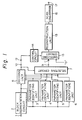
- a digital video signal supplied to an input terminal 1 is transmitted to a block segmentation circuit 2 for converting the order of data from the television scanning order to a predetermined order of blocks.
- F denotes a television image of one frame or one field.
- the pixel data is generated from the left end of each line to the right end thereof.
- the pixel data for successive lines is generated from the top to the bottom of the raster.
- block segmentation circuit 2 divides the image F into, for example, five parts in each of the vertical and horizontal directions, thereby forming twenty- five blocks B.
- Data of, for example, eight bits, in particular representing luminance data, is generated by block-segmentation circuit 2 for each block in accordance with the order of the numerals written for the respective blocks B.
- Fig. 3 shows one of the blocks B.
- the position of each pixel in the block B is represented by the coordinates of x and y axes having the center of the block as the origin o.
- the luminance value of the pixel located at the leftmost upper corner in the block B is Z 1
- the luminance values of the pixels successively arranged in the horizontal direction from the pixel having the luminance value Z 1 are Z 2 ,Z 3 ,...
- the luminance value of the pixel data located at the rightmost lower corner of the block B is Z M .
- the coordinates of the pixel having the luminance value Z i are expressed as (x i ,y i ).
- the output signal of block segmentation circuit 2 is supplied to four parameter identifying units 3,4,5 and 6 each using a different degree of plane or curved surface and to a deciding unit 8.
- the distribution of all of the luminance values of the pixels contained in one block can be approximately expressed by the coordinates (x,y) shown in Fig. 3.
- the virtual curved surface which is expressed by those luminance values can be approximated by a special curved surface.
- a predicted luminance Z i for the pixel having the coordinates (x i ,y i ) is expressed by in the case where it is approximated by a curved surface of degree 3, namely, by a cubic curved surface having two extrema.
- Z i is expressed by
- a 1 to a 10 are parameters.
- each parameter consists of eight bits.
- Deciding unit 8 obtains the distribution of the errors for every block from the errors between the predicted luminance value Z i to be obtained by use of the respective parameters and the luminance value Z 1 and generates an additional code to select the parameters which reduce the distribution of the errors and which use a curved surface of a low degree.
- This additional code consists of two bits.
- Selecting circuit 7 performs the following selecting operations in accordance with the additional code from deciding unit 8:
- the parameters selected by selecting circuit 7 are supplied therefrom to an output terminal 9.
- the additional code from deciding unit 8 is supplied to an output terminal 10. These parameters and additional code available at terminals 9 and 10, respectively, are transmitted.
- the parameters received at an input terminal 11 are supplied to a switching circuit 13, and the additional code received at an input terminal 12 is supplied to a control circuit 14.
- the additional code indicates the degree of the curved surface used to identify the parameters for every block.
- the control circuit 14 decodes the additional code and generates a control signal for controlling switching circuit 13.
- the parameters which identify the degree of the curved surface used at the transmission side are output from switching circuit 13. In other words, in the case of the 3- degree curved surface, ten parameters are output from the switching circuit 13. In the cases of the 2-degree, 1-degree and 0-degree curved surfaces, six, three and one parameters, respectively, are output from switching circuit 13.
- the switching circuit 13 outputs the data "0" in place of the unnecessary parameters.
- the parameters from switching circuit 13 are supplied to a reconstructing unit 15 which reconstructs the luminance value from the coordinate data of the block B and the received parameters.
- the reconstructed data from raconstructing unit 15 is supplied to a scan converter 16 in which the order of the data is returned to the scanning order of the television signal so that data for providing the reconstructed image is derived at an output terminal 17.
- the number of curved surfaces used to identify the parameters is not necessarily limited to four, but it is sufficient to use at least two curved surfaces having different degrees.
- M ⁇ M (4N+1) x (2N+1) ⁇ data in one block B are compressed to one to ten parameters, so that very substantial data compression can be accomplished.
- the identification of the parameters a 1 to a 10 by parameter identifying unit 3 will be explained hereinafter.
- the luminance values Z 1 to Z M of M pixels in the block B are predicted by fitting the 3-degree curved surface, they can be expressed by the following matrix operation in which the prediction errors are assumed to be e 1 ,e 2 ,...,e M .
- the coordinates (X 1 ,X 2 ,...,X M ,Y 1 ,Y 2 ,...,Y M ) of each luminance value in the block become the fixed data if the value of N corresponding to the block size is determined. Therefore, the term (coordinate data) of (W T W) -1 W T becomes the fixed data which is common to all blocks and can be generated by, for example, an ROM.
- a one-dimensional block is fitted by a straight line
- Fig. 4 One block consists of seven pixels on the same line and, as shown in Fig. 4, the x coordinate is formed with the central pixel having the value Z 4 as the origin. If the luminance values Z 1 ,Z 2 ,...,Z 7 of the respective pixels have changed, as shown in Fig. 4, the luminance values in the block are fitted by the straight line (ax + b) indicated by a broken line. Therefore, the luminance values of the respective pixels are represented by the following expression.
- parameters a and b are identified by the method of least squares.
- a quadratic curve (ax 2 + bx + c) instead of a straight line
- the data in the block is fitted by a curved surface instead of a straight line or curved line.
- F ig. 5 shows a specific circuit arrangement that may be used as the parameter identifying unit 3.
- the luminance value Z k from block segmentation circuit 2 is supplied through an input terminal 20 to ten multipliers 21,22,...,30, respectively.
- the coordinate data W k (l), W k (2),...,W k (10) of the luminance value Z k are supplied from a ROM (not shown) to multipliers 21 to 30, respectively.
- the output data from multipliers 21 to 30 are supplied to first input terminals of adders 31,32,...,40, respectively.
- the output data from adders 31 to 40 are supplied to registers 41,42,...,50, respectively, and to output terminals 51,52,...,60, respectively.
- the outputs of registers 41,42,...,50 are applied to second inputs of adders 31,32,...,40, respectively.
- An integrating circuit is constituted by each of the adders 31,32,...,40 and the paired register 41,42,...50, respectively.
- the registers 41 to 50 are reset each time the calculations of M luminance values of one block are finished.
- the parameters a 2 ,a 3 ,...,a 10 are derived at the output terminals 52, 53 ,..., 60, respectively.
- the parameter identifying unit 4 identifies six parameters a 5 ,a 6 ,...,a 10 and may have the circuit arrangement shown in Fig. 6. More particularly, unit 4 is shown to have an arrangement similar to that of parameter identifying unit 3, with the luminance value Z k being supplied through an input terminal 120 to six multipliers 125,126,...,130 which also receive the coordinate data W k (5),W k (6),...,W k (10).
- the resulting products are supplied from multipliers 125,126,...,130 to respective integrating circuits constituted by an adder 135 and a register 145, an adder 136 and a register 146,..., an adder 140 and a register 150, respectively, for providing parameters a 5 ,a 6 , ...a 10 at respective output terminals 155,156,...160.
- the parameter identifying unit 5 is similarly shown on Fig. 7 for identifying three parameters a 8 ,a 9 and a 10 . More particularly, in Fig. 7, the luminance value Z k is supplied through an input terminal 220 to three multipliers 228,229 and 230 which also receive the coordinate data Wk(8),Wk(9) and W k (10), respectively. The products are supplied from multipliers 228,229 and 230 to respective integrating circuits constituted by an adder 238 and a register 248, an adder 239 and a register 249, and an adder 240 and a register 250, respectively, for providing the parameters a 8 ,a 9 and a 10 at respective output terminals 258,259 and 260.
- parameter identifying unit 6 for identifying the single parameter a 10 may comprise an input terminal 320 through which luminance value Z k is supplied to a multiplier 330 which also receives the coordinate data W k (10).
- the product of multiplier 330 is supplied to an integrating circuit constituted by an adder 340 and a register 350 for providing the parameter a 10 at a respective output terminal 360.
- Deciding unit 8 decides the parameters so as to reduce the error distribution ( ⁇ ) and further to reduce the degree of the curved surface used to identify the parameters to as low a degree as possible among the parameters identified respectively by the parameter identifying units 3 to 6.
- deciding unit 8 may include an input terminal 61 through which the video data from block segmentation circuit 2 is supplied to a squaring circuit 62, an integrating circuit 73, and nine multipliers 63 to 71, respectively.
- the coordinate data (x 1 ,y i ,x i 2 ,x i y i ,y i 2 ,x i 3 , x i 2 y i , x i y i 2 ,y i 3 ) are supplied to multipliers 63 to 71 , respectively.
- the output of squaring circuit 62 is supplied to an integrating circuit 72, and the outputs of multipliers 63 to 71 are supplied to integrating circuits 74 to 82, respectively.
- Each of integrating circuit 72 which is supplied with the output of squaring circuit 62, integrating circuit 73 which is supplied with the luminance value Z., and integrating circuits 74 to 82 which are supplied with the multiplied outputs of multipliers 63 to 71 performs the M integrating operations (that is, adds the present input and the preceding added output) in correspondence to the number of pixels in one block.
- the outputs of integrating circuits 72 to 82 are selectively supplied to arithmetic operating circuits 83 to 86 each for obtaining the error distribution.
- the operating circuit 83 calculates the error distribution ⁇ 0 2 when the 0-degree curved surface (that is, a flat plane having no gradients) is used.
- the operating circuit 84 calculates the error distribution ⁇ 1 2 when the linear curved surface (that is, a flat plane with gradients) is used.
- the operating circuit 85 calculates the error distribution 02 2 when the quadratic curved surface is used.
- the operating circuit 86 calculates the error distribution ⁇ 3 2 when the cubic curved surface is used.
- the resultant error distributions ⁇ 0 2 , ⁇ 1 2 , ⁇ 2 2 and ⁇ 3 2 are supplied to a deciding circuit 87 which generates a control signal supplied to an output terminal 88 for causing selecting circuit 7 to select the proper parameters in accordance with the error distributions and the degree of the curved surface used for the parameter identification.
- one of a plurality of parameters is selected in consideration of both of the value of the error distribution and the degree of the curved surface used for fitting.
- the relation ( ⁇ 3 2 ⁇ ⁇ 2 2 ⁇ ⁇ 1 2 ⁇ ⁇ 0 2 ) exists among the error distributions.
- the above relation of the magnitudes of the error distributions holds true.
- a smooth image (block) a similar relation of the error distributions is obtained, but there are hardly any differences between the magnitudes of the error distributions. If the error distributions are almost equal, the parameters which are selected are those obtained as the result of the fitting process using the curved surface of a low degree and which can permit the compression ratio r to be raised.
- the square sum ( ⁇ (Z i ) 2 ) of the luminance values and the integrated value ( ⁇ (Z i )) of the luminance values are calculated by squaring circuit 62 and integrating circuit 72 and by integrating circuit 73, respectively.
- the error distribution ⁇ 0 2 is obtained by operating circuit 83 in accordance with the above expression.
- the error distribution ⁇ 1 2 can be obtained by use of the parameters a 8 ,a 9 , and a 10 which were identified as ⁇ (Z i 2 ), ⁇ (Z i ), ⁇ (Z i ⁇ x i ), and ⁇ (Z i ⁇ y i ).
- the square sum ⁇ (Z i 2 ) of the luminance value and the integrated luminance value ⁇ (Z i ) are obtained by squaring circuit 62 and integrating circuit 72, and by integrating circuit 73, respectively.
- ⁇ (Z i ⁇ x i ) is derived by multiplier 63 and integrating circuit 74 and ⁇ (Z i ⁇ y i ) is obtained by multiplier 64 and integrating circuit 75.
- ⁇ (Z i 2 ), ⁇ (Z i ), ⁇ (Z i ⁇ xi) and ⁇ (Z i ⁇ y i ) are obtained as indicated above.
- ⁇ (Z i ⁇ x i 2 ) is obtained by multiplier 65 and integrating circuit 76
- ⁇ (Z i ⁇ x i ⁇ y i ) is obtained by multiplier 66 and integrating circuit 77
- I (Z i -y i 2 ) is obtained by multiplier 67 and integrating circuit 78.
- Operating circuit 85 calculates error distribution ⁇ 2 2 from the outputs of the seven integrating circuits 72 to 78.
- ⁇ (Z i x i 3 ) is obtained by multiplier 68 and integrating circuit 79.
- ⁇ (Z i ⁇ x i 2 ⁇ y i ), ⁇ (Z i ⁇ x i ⁇ y i 2 ), and ⁇ (Z i ⁇ y i 3 ) are obtained by multiplier 69 and integrating circuit 80, multiplier 70 and integrating circuit 81, and multiplier 71 and integrating circuit 82, respectively.
- the outputs of integrating circuits 72 to 75 and 79 to 82 are supplied to operating circuit 86 which calculates error distribution 3 2 therefrom.
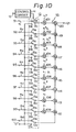
- Switching circuit 13 and reconstructing unit 15 at the reception side may be constituted as shown in Fig. 10.
- the parameters a 1 , a 2 ,...,a 10 of the one, three, six or ten parameter data received at terminal 11 on Fig. 1 are applied to input terminals 91,92,...,100, respectively, on Fig. 10.
- the input terminals 91,92,...,100 are connected to respective first contacts 13a of switching circuit 13 which are paired with respective second contacts 13b all connected to a source of zero data "0".
- the first and second contacts 13a and 13b of each pair thereof are alternately engaged by an associated movable contact 13c in accordance with the control signal applied to switching circuit 13 by control circuit 14 in response to the additional code received at terminal 12.
- control circuit 14 causes switching circuit 13 to engage a movable contact 13c with the one contact 13a connected to terminal 100 which receives the parameter a 10 , while all of the other movable contacts 13c are made to engage the contacts 13b which receive zero data "0".
- switching circuit 13 engages its movable contacts 13c with the respective contacts 13a connected to input terminals 98,99 and 100 which receive the parameters a 8 ,a 9 and a 10 , respectively, while all of the other movable contacts 13c are engaged with the respective contacts 13b connected with the source of zero data "0".
- switching circuit 13 engages its movable contacts 13c with the respective contacts 13a connected to input terminals 95,96,97,98,99 and 100 which receive the parameters a 5 ,a 6 , a 7 ,a 8 ,a 9 and a 10 , respectively, while all of the other movable contacts 13a are engaged the respective contacts 13b connected to the source of zero data "0".
- the additional code (11) is received at terminal 12
- all of the movable contacts 13c of switching circuit 13 are engaged with the respective contacts 13a connected with the terminals 91,92,...,100 which receive the ten parameters a 1 ,a 2 ,...,a 10 , respectively.
- Reconstructing unit 15 has an ROM (not shown) which generates different coordinate data M times during the period of time in which the received parameters of one block are supplied from switching circuit 13 to reconstructing unit 15, and in which period of time M reconstructed luminance values are sequentially provided at an output terminal 121 for application to scan converter 16.
- reconstructing unit 15 is shown to include multipliers 101,102,...,109 connected to the movable contacts 13c of switching circuit 13 associated with the first contacts 13a which are connected with input terminals 91,92,...,100 receiving parameters a 1 ,a 2 ,....a 10 , respectively.
- the coordinate data (x i 3 ,x i 2 y i ,x i y i 2 ,y i 3 ,x i 2 , x i y i ,y i 2 ,x i and y i of the ith pixel are supplied by the previously mentioned ROM to multipliers 101,102,...,109, respectively.
- the present invention is not limited to a system in which the degree of the n-degree curved surface is selected, as described above with reference to selecting circuit 7 and deciding unit 8, but may be also applied to the case where it is possible to approximate by only a surface curved to a specific degree. In such case, selecting circuit 7 and deciding unit 8 may be omitted.
- the coordinate data used for identifying the parameters is unchanged from block-to-block so that it may be generated by a ROM. Therefore, the parameter identifying units can be readily constituted by multiplying, adding and register elements, as on Figs. 5-8.
Landscapes
- Engineering & Computer Science (AREA)
- Multimedia (AREA)
- Signal Processing (AREA)
- Compression Or Coding Systems Of Tv Signals (AREA)
- Communication Control (AREA)
- Reduction Or Emphasis Of Bandwidth Of Signals (AREA)
- Compression, Expansion, Code Conversion, And Decoders (AREA)
- Image Processing (AREA)
- Compression Of Band Width Or Redundancy In Fax (AREA)
Priority Applications (1)
| Application Number | Priority Date | Filing Date | Title |
|---|---|---|---|
| AT86309905T ATE79996T1 (de) | 1985-12-18 | 1986-12-18 | Verfahren und vorrichtung fuer die uebermittlung von digitalen daten und vorrichtung zum dekodieren von digitalen daten. |
Applications Claiming Priority (2)
| Application Number | Priority Date | Filing Date | Title |
|---|---|---|---|
| JP284998/85 | 1985-12-18 | ||
| JP28499885A JP2612557B2 (ja) | 1985-12-18 | 1985-12-18 | データ伝送受信システム及びデータ復号装置 |
Publications (3)
| Publication Number | Publication Date |
|---|---|
| EP0227439A2 true EP0227439A2 (de) | 1987-07-01 |
| EP0227439A3 EP0227439A3 (en) | 1988-07-20 |
| EP0227439B1 EP0227439B1 (de) | 1992-08-26 |
Family
ID=17685819
Family Applications (1)
| Application Number | Title | Priority Date | Filing Date |
|---|---|---|---|
| EP19860309905 Expired - Lifetime EP0227439B1 (de) | 1985-12-18 | 1986-12-18 | Verfahren und Vorrichtung für die Übermittlung von digitalen Daten und Vorrichtung zum Dekodieren von digitalen Daten |
Country Status (8)
| Country | Link |
|---|---|
| US (1) | US4772947A (de) |
| EP (1) | EP0227439B1 (de) |
| JP (1) | JP2612557B2 (de) |
| KR (1) | KR950002673B1 (de) |
| AT (1) | ATE79996T1 (de) |
| AU (1) | AU597921B2 (de) |
| CA (1) | CA1307840C (de) |
| DE (1) | DE3686566T2 (de) |
Cited By (1)
| Publication number | Priority date | Publication date | Assignee | Title |
|---|---|---|---|---|
| DE19614595A1 (de) * | 1996-04-13 | 1997-10-16 | Singulus Technologies Gmbh | Vorrichtung zur Kathodenzerstäubung |
Families Citing this family (80)
| Publication number | Priority date | Publication date | Assignee | Title |
|---|---|---|---|---|
| US4947447A (en) * | 1986-04-24 | 1990-08-07 | Hitachi, Ltd. | Method for data coding |
| JPS63269882A (ja) * | 1987-04-28 | 1988-11-08 | Mitsubishi Electric Corp | 画像符号化伝送装置 |
| EP0624036A1 (de) * | 1987-04-28 | 1994-11-09 | Mitsubishi Denki Kabushiki Kaisha | System zur Bildcodierung und -decodierung |
| FR2628276B1 (fr) * | 1988-03-02 | 1991-06-28 | France Etat | Procede de reduction de debit d'une sequence de donnees d'assistance a la reconstitution d'une image electronique a partir d'un signal sous-echantillonne |
| DE3906712A1 (de) * | 1989-03-03 | 1990-09-06 | Thomson Brandt Gmbh | Elektronisches bildwiedergabegeraet |
| US5537494A (en) * | 1990-05-29 | 1996-07-16 | Axiom Innovation Limited | Video image data encoding and compression system using edge detection and luminance profile matching |
| US5193004A (en) * | 1990-12-03 | 1993-03-09 | The Trustees Of Columbia University In The City Of New York | Systems and methods for coding even fields of interlaced video sequences |
| JP2586260B2 (ja) * | 1991-10-22 | 1997-02-26 | 三菱電機株式会社 | 適応的ブロッキング画像符号化装置 |
| KR960006761B1 (ko) * | 1991-12-07 | 1996-05-23 | 삼성전자주식회사 | 변환방식의 적응적 선택에 의한 변환부호화 및 복호화방법 |
| EP0562672A3 (en) * | 1992-03-22 | 1994-07-13 | Igp Res & Dev Ltd | Process of picture representation by data compression |
| JPH08140091A (ja) * | 1994-11-07 | 1996-05-31 | Kokusai Electric Co Ltd | 画像伝送システム |
| US5734433A (en) * | 1995-06-21 | 1998-03-31 | Sony Corporation | Picture encoding apparatus, picture encoding method, picture encoding and transmitting method, and picture record medium |
| US5859990A (en) * | 1995-12-29 | 1999-01-12 | Intel Corporation | System for transferring data segments from a first storage device to a second storage device using an alignment stage including even and odd temporary devices |
| US6163868A (en) | 1997-10-23 | 2000-12-19 | Sony Corporation | Apparatus and method for providing robust error recovery for errors that occur in a lossy transmission environment |
| US6282684B1 (en) | 1997-10-23 | 2001-08-28 | Sony Corporation | Apparatus and method for recovery of data in a lossy transmission environment |
| US6581170B1 (en) | 1997-10-23 | 2003-06-17 | Sony Corporation | Source coding to provide for robust error recovery during transmission losses |
| US6519369B1 (en) | 1999-02-12 | 2003-02-11 | Sony Corporation | Method and apparatus for filter tap expansion |
| US6154761A (en) * | 1999-02-12 | 2000-11-28 | Sony Corporation | Classified adaptive multiple processing system |
| US6535148B1 (en) | 1999-02-12 | 2003-03-18 | Sony Corporation | Method and apparatus for truncated decoding |
| US6363118B1 (en) | 1999-02-12 | 2002-03-26 | Sony Corporation | Apparatus and method for the recovery of compression constants in the encoded domain |
| US6621936B1 (en) | 1999-02-12 | 2003-09-16 | Sony Corporation | Method and apparatus for spatial class reduction |
| US6151416A (en) * | 1999-02-12 | 2000-11-21 | Sony Corporation | Method and apparatus for adaptive class tap selection according to multiple classification |
| US6307560B1 (en) | 1999-02-12 | 2001-10-23 | Sony Corporation | Classified adaptive spatio-temporal format conversion method and apparatus |
| US6307979B1 (en) | 1999-02-12 | 2001-10-23 | Sony Corporation | Classified adaptive error recovery method and apparatus |
| US6170074B1 (en) | 1999-02-12 | 2001-01-02 | Sony Corporation | Source coding to provide for robust error recovery |
| US6192161B1 (en) | 1999-02-12 | 2001-02-20 | Sony Corporation | Method and apparatus for adaptive filter tap selection according to a class |
| US6591398B1 (en) | 1999-02-12 | 2003-07-08 | Sony Corporation | Multiple processing system |
| US6178266B1 (en) | 1999-02-12 | 2001-01-23 | Sony Corporation | Method and apparatus for the recovery of compression constants in the encoded domain |
| US7010737B2 (en) * | 1999-02-12 | 2006-03-07 | Sony Corporation | Method and apparatus for error data recovery |
| US6697489B1 (en) | 1999-03-30 | 2004-02-24 | Sony Corporation | Method and apparatus for securing control words |
| US7565546B2 (en) | 1999-03-30 | 2009-07-21 | Sony Corporation | System, method and apparatus for secure digital content transmission |
| US7730300B2 (en) | 1999-03-30 | 2010-06-01 | Sony Corporation | Method and apparatus for protecting the transfer of data |
| US6549672B1 (en) | 1999-06-29 | 2003-04-15 | Sony Corporation | Method and apparatus for recovery of encoded data using central value |
| US6493842B1 (en) | 1999-06-29 | 2002-12-10 | Sony Corporation | Time-varying randomization for data synchronization and implicit information transmission |
| US6473876B1 (en) | 1999-06-29 | 2002-10-29 | Sony Corporation | Method and apparatus for encoding of bitstreams using rotation |
| US6389562B1 (en) | 1999-06-29 | 2002-05-14 | Sony Corporation | Source code shuffling to provide for robust error recovery |
| US6522785B1 (en) | 1999-09-24 | 2003-02-18 | Sony Corporation | Classified adaptive error recovery method and apparatus |
| US6351494B1 (en) | 1999-09-24 | 2002-02-26 | Sony Corporation | Classified adaptive error recovery method and apparatus |
| US6539517B1 (en) | 1999-11-09 | 2003-03-25 | Sony Corporation | Data transformation for explicit transmission of control information |
| US7039614B1 (en) | 1999-11-09 | 2006-05-02 | Sony Corporation | Method for simulcrypting scrambled data to a plurality of conditional access devices |
| US6754371B1 (en) | 1999-12-07 | 2004-06-22 | Sony Corporation | Method and apparatus for past and future motion classification |
| US7225164B1 (en) | 2000-02-15 | 2007-05-29 | Sony Corporation | Method and apparatus for implementing revocation in broadcast networks |
| US20030206631A1 (en) * | 2000-06-22 | 2003-11-06 | Candelore Brant L. | Method and apparatus for scrambling program data for furture viewing |
| US7248257B2 (en) * | 2001-02-14 | 2007-07-24 | Technion Research & Development Foundation Ltd. | Low bandwidth transmission of 3D graphical data |
| US7350082B2 (en) | 2001-06-06 | 2008-03-25 | Sony Corporation | Upgrading of encryption |
| US7747853B2 (en) | 2001-06-06 | 2010-06-29 | Sony Corporation | IP delivery of secure digital content |
| US7336787B2 (en) | 2001-06-06 | 2008-02-26 | Sony Corporation | Critical packet partial encryption |
| US7895616B2 (en) | 2001-06-06 | 2011-02-22 | Sony Corporation | Reconstitution of program streams split across multiple packet identifiers |
| US7242773B2 (en) | 2002-09-09 | 2007-07-10 | Sony Corporation | Multiple partial encryption using retuning |
| US7376233B2 (en) | 2002-01-02 | 2008-05-20 | Sony Corporation | Video slice and active region based multiple partial encryption |
| US7155012B2 (en) | 2002-01-02 | 2006-12-26 | Sony Corporation | Slice mask and moat pattern partial encryption |
| US7218738B2 (en) | 2002-01-02 | 2007-05-15 | Sony Corporation | Encryption and content control in a digital broadcast system |
| US7233669B2 (en) | 2002-01-02 | 2007-06-19 | Sony Corporation | Selective encryption to enable multiple decryption keys |
| US7765567B2 (en) | 2002-01-02 | 2010-07-27 | Sony Corporation | Content replacement by PID mapping |
| US7039938B2 (en) | 2002-01-02 | 2006-05-02 | Sony Corporation | Selective encryption for video on demand |
| US7302059B2 (en) | 2002-01-02 | 2007-11-27 | Sony Corporation | Star pattern partial encryption |
| US7823174B2 (en) | 2002-01-02 | 2010-10-26 | Sony Corporation | Macro-block based content replacement by PID mapping |
| US7292691B2 (en) | 2002-01-02 | 2007-11-06 | Sony Corporation | Progressive video refresh slice detection |
| US7215770B2 (en) | 2002-01-02 | 2007-05-08 | Sony Corporation | System and method for partially encrypted multimedia stream |
| US7530084B2 (en) | 2002-05-28 | 2009-05-05 | Sony Corporation | Method and apparatus for synchronizing dynamic graphics |
| US8818896B2 (en) | 2002-09-09 | 2014-08-26 | Sony Corporation | Selective encryption with coverage encryption |
| US7724907B2 (en) | 2002-11-05 | 2010-05-25 | Sony Corporation | Mechanism for protecting the transfer of digital content |
| US8572408B2 (en) | 2002-11-05 | 2013-10-29 | Sony Corporation | Digital rights management of a digital device |
| US8667525B2 (en) | 2002-12-13 | 2014-03-04 | Sony Corporation | Targeted advertisement selection from a digital stream |
| US8645988B2 (en) | 2002-12-13 | 2014-02-04 | Sony Corporation | Content personalization for digital content |
| US20040165586A1 (en) * | 2003-02-24 | 2004-08-26 | Read Christopher Jensen | PID filters based network routing |
| US7409702B2 (en) | 2003-03-20 | 2008-08-05 | Sony Corporation | Auxiliary program association table |
| US7292692B2 (en) | 2003-03-25 | 2007-11-06 | Sony Corporation | Content scrambling with minimal impact on legacy devices |
| US7286667B1 (en) | 2003-09-15 | 2007-10-23 | Sony Corporation | Decryption system |
| US7620180B2 (en) | 2003-11-03 | 2009-11-17 | Sony Corporation | Preparation of content for multiple conditional access methods in video on demand |
| US7343013B2 (en) | 2003-12-16 | 2008-03-11 | Sony Corporation | Composite session-based encryption of video on demand content |
| US7346163B2 (en) | 2003-10-31 | 2008-03-18 | Sony Corporation | Dynamic composition of pre-encrypted video on demand content |
| US7263187B2 (en) | 2003-10-31 | 2007-08-28 | Sony Corporation | Batch mode session-based encryption of video on demand content |
| US7853980B2 (en) | 2003-10-31 | 2010-12-14 | Sony Corporation | Bi-directional indices for trick mode video-on-demand |
| US7895617B2 (en) | 2004-12-15 | 2011-02-22 | Sony Corporation | Content substitution editor |
| US8041190B2 (en) | 2004-12-15 | 2011-10-18 | Sony Corporation | System and method for the creation, synchronization and delivery of alternate content |
| US8185921B2 (en) | 2006-02-28 | 2012-05-22 | Sony Corporation | Parental control of displayed content using closed captioning |
| US7555464B2 (en) | 2006-03-01 | 2009-06-30 | Sony Corporation | Multiple DRM management |
| EP2122573B1 (de) * | 2007-01-26 | 2018-05-30 | Telefonaktiebolaget LM Ericsson (publ) | Bewegungsschätzung für nicht abgedeckte rahmenbereiche |
| US8098247B2 (en) * | 2009-09-24 | 2012-01-17 | Crucs Holdings, Llc | Systems and methods for geometric data compression and encryption |
Family Cites Families (9)
| Publication number | Priority date | Publication date | Assignee | Title |
|---|---|---|---|---|
| US4541012A (en) * | 1982-01-04 | 1985-09-10 | Compression Labs, Inc. | Video bandwidth reduction system employing interframe block differencing and transform domain coding |
| IT1155557B (it) * | 1982-07-19 | 1987-01-28 | Cselt Centro Studi Lab Telecom | Metdodo e dispositivo per la codifica del segnale d immagine con riduzione di ridondanza a distorsione localmente uniforme |
| GB2129652B (en) * | 1982-10-27 | 1986-06-04 | Matsushita Electric Industrial Co Ltd | Method and apparatus for processing image signal |
| FR2543384A1 (fr) * | 1983-03-22 | 1984-09-28 | Thomson Csf | Procede de codage adaptatif, et de decodage, d'une image de television, et dispositifs pour la mise en oeuvre de ce procede |
| EP0185533B1 (de) * | 1984-12-19 | 1991-03-27 | Sony Corporation | Hochleistungsfähige Technik zur Kodierung eines digitalen Videosignals |
| JPH0793724B2 (ja) * | 1984-12-21 | 1995-10-09 | ソニー株式会社 | テレビジョン信号の高能率符号化装置及び符号化方法 |
| DE3684047D1 (de) * | 1985-07-02 | 1992-04-09 | Matsushita Electric Industrial Co Ltd | Vorrichtung zur blockkodierung. |
| JP2512894B2 (ja) * | 1985-11-05 | 1996-07-03 | ソニー株式会社 | 高能率符号化/復号装置 |
| US4704628A (en) * | 1986-07-16 | 1987-11-03 | Compression Labs, Inc. | Combined intraframe and interframe transform coding system |
-
1985
- 1985-12-18 JP JP28499885A patent/JP2612557B2/ja not_active Expired - Lifetime
-
1986
- 1986-12-17 US US06/942,701 patent/US4772947A/en not_active Expired - Lifetime
- 1986-12-17 CA CA 525554 patent/CA1307840C/en not_active Expired - Lifetime
- 1986-12-18 EP EP19860309905 patent/EP0227439B1/de not_active Expired - Lifetime
- 1986-12-18 AU AU66693/86A patent/AU597921B2/en not_active Expired
- 1986-12-18 AT AT86309905T patent/ATE79996T1/de not_active IP Right Cessation
- 1986-12-18 DE DE8686309905T patent/DE3686566T2/de not_active Expired - Lifetime
- 1986-12-18 KR KR1019860010893A patent/KR950002673B1/ko not_active Expired - Lifetime
Non-Patent Citations (1)
| Title |
|---|
| IEEE PUBLICATION ICASSP 83, INTERNATIONAL CONFERENCE ON ACOUSTICS SPEECH AND SIGNAL PROCESSING, BOSTON, vol. 3, 14 April 1983 (1983-04-14), pages 1232 - 1235 |
Cited By (1)
| Publication number | Priority date | Publication date | Assignee | Title |
|---|---|---|---|---|
| DE19614595A1 (de) * | 1996-04-13 | 1997-10-16 | Singulus Technologies Gmbh | Vorrichtung zur Kathodenzerstäubung |
Also Published As
| Publication number | Publication date |
|---|---|
| US4772947B1 (de) | 1989-05-30 |
| EP0227439B1 (de) | 1992-08-26 |
| AU6669386A (en) | 1987-06-25 |
| JP2612557B2 (ja) | 1997-05-21 |
| CA1307840C (en) | 1992-09-22 |
| KR950002673B1 (ko) | 1995-03-24 |
| JPS62143585A (ja) | 1987-06-26 |
| DE3686566T2 (de) | 1993-01-28 |
| ATE79996T1 (de) | 1992-09-15 |
| EP0227439A3 (en) | 1988-07-20 |
| AU597921B2 (en) | 1990-06-14 |
| DE3686566D1 (de) | 1992-10-01 |
| KR870006750A (ko) | 1987-07-14 |
| US4772947A (en) | 1988-09-20 |
Similar Documents
| Publication | Publication Date | Title |
|---|---|---|
| US4772947A (en) | Method and apparatus for transmitting compression video data and decoding the same for reconstructing an image from the received data | |
| EP0228820B1 (de) | Verfahren und Vorrichtung zur Sendung und Dekodierung von Videodaten | |
| EP1034505B1 (de) | System und verfahren für blockbasierte bildkompression mit fester rate unter verwendung von abgeleiteten pixelwerten | |
| Zaccarin et al. | A novel approach for coding color quantized images | |
| EP1122956B1 (de) | Extrapolation von Pixelwerten eines in einem Block enthaltenen Videoobjektes | |
| USRE33547E (en) | Graded facsimile image signal coding system | |
| EP0368460A1 (de) | Kodiergerät | |
| EP1445949B1 (de) | Schaltung und Verfahren zur Produktsummenberechnung | |
| US5590222A (en) | Image signal processing apparatus utilizing a 2D Haar transform and adaptive selection of images based on a parameter such as a ratio of coefficients for reducing block distortion and method thereof | |
| US6134348A (en) | Image processing apparatus and method | |
| US5710838A (en) | Apparatus for encoding a video signal by using modified block truncation and contour coding methods | |
| US5774596A (en) | Adaptive contour coding method for encoding a contour image in a video signal | |
| EP0607696A2 (de) | Bildverarbeitungsverfahren | |
| EP0457976B1 (de) | Gerät zur Videosignalkompression | |
| US5990956A (en) | Method and apparatus for padding a video signal for shape adaptive transformation | |
| EP0467054B1 (de) | Kodier- und Dekodierverfahren für ein Bildsignal unter Verwendung von überlappenden Blöcken mit variablen Abmessungen und Vorrichtung dazu | |
| JP4136031B2 (ja) | 輪郭線符号化装置 | |
| EP0858226B1 (de) | Verfahren und Vorrichtung zur Kodierung von Objektkonturen mittels Scheiteleinfügungstechnik | |
| JP2550021B2 (ja) | デ−タ圧縮を用いた信号伝送受信方法 | |
| JP2841314B2 (ja) | データ伝送方法および伝送装置 | |
| JPS61147690A (ja) | 高能率符号の復号装置 | |
| JPS63256080A (ja) | ブロツク符号化の復号装置 | |
| JPS62120181A (ja) | デイジタル多値画像の適応符号化方法 | |
| JP2696869B2 (ja) | 画像符号化装置 | |
| Hasegawa et al. | Image data compression with nonuniform block segmentation and luminance approximation using bilinear curved surface patches |
Legal Events
| Date | Code | Title | Description |
|---|---|---|---|
| PUAI | Public reference made under article 153(3) epc to a published international application that has entered the european phase |
Free format text: ORIGINAL CODE: 0009012 |
|
| 17P | Request for examination filed |
Effective date: 19861224 |
|
| AK | Designated contracting states |
Kind code of ref document: A2 Designated state(s): AT DE FR GB NL |
|
| PUAL | Search report despatched |
Free format text: ORIGINAL CODE: 0009013 |
|
| AK | Designated contracting states |
Kind code of ref document: A3 Designated state(s): AT DE FR GB NL |
|
| 17Q | First examination report despatched |
Effective date: 19910313 |
|
| GRAA | (expected) grant |
Free format text: ORIGINAL CODE: 0009210 |
|
| AK | Designated contracting states |
Kind code of ref document: B1 Designated state(s): AT DE FR GB NL |
|
| REF | Corresponds to: |
Ref document number: 79996 Country of ref document: AT Date of ref document: 19920915 Kind code of ref document: T |
|
| REF | Corresponds to: |
Ref document number: 3686566 Country of ref document: DE Date of ref document: 19921001 |
|
| ET | Fr: translation filed | ||
| PLBE | No opposition filed within time limit |
Free format text: ORIGINAL CODE: 0009261 |
|
| STAA | Information on the status of an ep patent application or granted ep patent |
Free format text: STATUS: NO OPPOSITION FILED WITHIN TIME LIMIT |
|
| 26N | No opposition filed | ||
| REG | Reference to a national code |
Ref country code: GB Ref legal event code: IF02 |
|
| PGFP | Annual fee paid to national office [announced via postgrant information from national office to epo] |
Ref country code: NL Payment date: 20051204 Year of fee payment: 20 |
|
| PGFP | Annual fee paid to national office [announced via postgrant information from national office to epo] |
Ref country code: FR Payment date: 20051208 Year of fee payment: 20 |
|
| PGFP | Annual fee paid to national office [announced via postgrant information from national office to epo] |
Ref country code: AT Payment date: 20051213 Year of fee payment: 20 |
|
| PGFP | Annual fee paid to national office [announced via postgrant information from national office to epo] |
Ref country code: GB Payment date: 20051214 Year of fee payment: 20 |
|
| PGFP | Annual fee paid to national office [announced via postgrant information from national office to epo] |
Ref country code: DE Payment date: 20051215 Year of fee payment: 20 |
|
| PG25 | Lapsed in a contracting state [announced via postgrant information from national office to epo] |
Ref country code: GB Free format text: LAPSE BECAUSE OF EXPIRATION OF PROTECTION Effective date: 20061217 |
|
| PG25 | Lapsed in a contracting state [announced via postgrant information from national office to epo] |
Ref country code: NL Free format text: LAPSE BECAUSE OF EXPIRATION OF PROTECTION Effective date: 20061218 |
|
| REG | Reference to a national code |
Ref country code: GB Ref legal event code: PE20 |
|
| NLV7 | Nl: ceased due to reaching the maximum lifetime of a patent |
Effective date: 20061218 |