EP0467054B1 - Kodier- und Dekodierverfahren für ein Bildsignal unter Verwendung von überlappenden Blöcken mit variablen Abmessungen und Vorrichtung dazu - Google Patents
Kodier- und Dekodierverfahren für ein Bildsignal unter Verwendung von überlappenden Blöcken mit variablen Abmessungen und Vorrichtung dazu Download PDFInfo
- Publication number
- EP0467054B1 EP0467054B1 EP19910108684 EP91108684A EP0467054B1 EP 0467054 B1 EP0467054 B1 EP 0467054B1 EP 19910108684 EP19910108684 EP 19910108684 EP 91108684 A EP91108684 A EP 91108684A EP 0467054 B1 EP0467054 B1 EP 0467054B1
- Authority
- EP
- European Patent Office
- Prior art keywords
- block
- signal
- blocks
- inverse
- signals
- Prior art date
- Legal status (The legal status is an assumption and is not a legal conclusion. Google has not performed a legal analysis and makes no representation as to the accuracy of the status listed.)
- Expired - Lifetime
Links
- 238000000034 method Methods 0.000 title claims description 21
- 230000006870 function Effects 0.000 claims description 73
- 230000015654 memory Effects 0.000 description 20
- 238000010276 construction Methods 0.000 description 16
- 239000002131 composite material Substances 0.000 description 12
- 230000004044 response Effects 0.000 description 8
- 238000010586 diagram Methods 0.000 description 7
- 239000011159 matrix material Substances 0.000 description 6
- 230000002194 synthesizing effect Effects 0.000 description 6
- XUFQPHANEAPEMJ-UHFFFAOYSA-N famotidine Chemical compound NC(N)=NC1=NC(CSCCC(N)=NS(N)(=O)=O)=CS1 XUFQPHANEAPEMJ-UHFFFAOYSA-N 0.000 description 5
- 238000012545 processing Methods 0.000 description 5
- 238000005070 sampling Methods 0.000 description 4
- 239000012141 concentrate Substances 0.000 description 3
- 230000000694 effects Effects 0.000 description 2
- 230000001965 increasing effect Effects 0.000 description 2
- 230000003044 adaptive effect Effects 0.000 description 1
- 238000013459 approach Methods 0.000 description 1
- 230000005540 biological transmission Effects 0.000 description 1
- 230000015572 biosynthetic process Effects 0.000 description 1
- 230000000903 blocking effect Effects 0.000 description 1
- 238000007796 conventional method Methods 0.000 description 1
- 230000003247 decreasing effect Effects 0.000 description 1
- 238000013461 design Methods 0.000 description 1
- 230000002708 enhancing effect Effects 0.000 description 1
- 238000013139 quantization Methods 0.000 description 1
- 238000003786 synthesis reaction Methods 0.000 description 1
- 230000000007 visual effect Effects 0.000 description 1
Images


Classifications
-
- H—ELECTRICITY
- H04—ELECTRIC COMMUNICATION TECHNIQUE
- H04N—PICTORIAL COMMUNICATION, e.g. TELEVISION
- H04N19/00—Methods or arrangements for coding, decoding, compressing or decompressing digital video signals
- H04N19/85—Methods or arrangements for coding, decoding, compressing or decompressing digital video signals using pre-processing or post-processing specially adapted for video compression
- H04N19/86—Methods or arrangements for coding, decoding, compressing or decompressing digital video signals using pre-processing or post-processing specially adapted for video compression involving reduction of coding artifacts, e.g. of blockiness
-
- H—ELECTRICITY
- H04—ELECTRIC COMMUNICATION TECHNIQUE
- H04N—PICTORIAL COMMUNICATION, e.g. TELEVISION
- H04N19/00—Methods or arrangements for coding, decoding, compressing or decompressing digital video signals
- H04N19/50—Methods or arrangements for coding, decoding, compressing or decompressing digital video signals using predictive coding
- H04N19/503—Methods or arrangements for coding, decoding, compressing or decompressing digital video signals using predictive coding involving temporal prediction
- H04N19/51—Motion estimation or motion compensation
- H04N19/527—Global motion vector estimation
-
- H—ELECTRICITY
- H04—ELECTRIC COMMUNICATION TECHNIQUE
- H04N—PICTORIAL COMMUNICATION, e.g. TELEVISION
- H04N19/00—Methods or arrangements for coding, decoding, compressing or decompressing digital video signals
- H04N19/90—Methods or arrangements for coding, decoding, compressing or decompressing digital video signals using coding techniques not provided for in groups H04N19/10-H04N19/85, e.g. fractals
- H04N19/96—Tree coding, e.g. quad-tree coding
Definitions
- the present invention relates to methods and apparatuses for coding and decoding a picture signal or similar bidimensional signal block by block.
- Schiller divides an image signal into blocks each having 2N x 2N pixels (N being a natural number) and overlapping adjacent blocks by half the block size in four directions which are perpendicular to the four sides thereof.
- An input pixel signal representative of 2N x 2N points is coded into a transformed signal representative of N x N points by transform equations which will be described later, and then the transformed signal is transmitted.
- the N x N transformed signal is transformed into a 2N x 2N inverse-transformed signal by an inverse procedure. Subsequently, this inverse-transformed signal and the inverse-transformed signals of the associated regions of the overlapping blocks are added to produce a decoded signal.
- Cheng-Tie Chen reported a unique procedure which splits a picture signal into non-overlapping bidimensional blocks of variable sizes and effects transform and coding in each of the blocks by Discrete Cosine Transform (DCT) in "Adaptive Transform Coding Via Quadtree-Based Variable Block Size DCT” at 1989 INTERNATIONAL CONFERENCE ON ACCOUSTICS, SPEECH, AND SIGNAL PROCESSING, Volume 3, MULTIDIMENSIONAL SIGNAL PROCESSING AUDIO & ELECTROACOUSTICS, held in Glasgow, May 23-26, 1989.
- DCT Discrete Cosine Transform
- (i + 1) kinds of block sizes at maximum i.e., N x N to M x M block sizes may be generated, depending on the degree to which the conditions are satisfied. Coding and decoding are effected with each of such blocks to enhance efficiency.
- the Chen's coding and decoding scheme suffers from the previously stated block boundary artifacts since it divides an input signal into blocks such that the blocks do not overlap one another.
- the Schiller's method and Malvar's method both are not practicable unless blocks of the same size overlap, i.e., correct results of decoding are not achievable when blocks of different sizes are used.
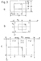
- the block P is constituted by a 2N x 2N pixel signal and overlaps blocks 7 and 8 (Fig. 1c) and blocks 5 and 6 (Fig. 1b) in directions x and y, respectively, by half the block size each.
- the block P overlaps blocks 1 and 3 which overlap the block 5 in the direction x by half the block size and blocks 2 and 4 which overlap the block 6 in the direction x by half the block size, over an N x N region (Fig. 1a).
- the block P overlaps with eight blocks in total.
- the blocks shown in Figs. 1a-1c appear as shown in Fig. 2 when seen from the above.
- the equation (l) corresponds to subsampling signals at 2N x 2N points in the frequency domain.
- the inverse-transformed signals of all the blocks which occupy the same space are added to produce a decoded signal.
- any region inside the block P overlies four blocks.
- the inverse-transformed signals corresponding to the same regions of the overlapping four blocks are added to produce a decoded signal.
- Decoded signals at the block boundaries can also be produced if the inverse-transformed signals of the plurality of blocks are added, whereby block boundary artifacts are reduced.
- the present invention divides a bidimensional input picture signal into a plurality of blocks each having a particular size by use of some basis.
- the basis to be used may be implemented as the previously mentioned Chen's method or any other method which is selected by comparing the amounts of code, the lower frequency range, power intensity, etc.
- a block of interest hereinafter referred to as a block P
- the present invention performs coding by using input signals representative of a 2M x 2N range centering around the block P.
- the transformed signal X p (k, i) is transmitted together with block division information which may be, for example, the origin and the horizontal and vertical sizes of the block.
- block division information which may be, for example, the origin and the horizontal and vertical sizes of the block.
- the present invention produces an inverse-transformed signal y p (m,n) of the transformed signal X p (k, i) by using window functions f AM (m) and f BN (n) prepared beforehand in association with the above-mentioned window functions h AM (m) and h BN (n) and an equation: Subsequently, the inverse-transformed signals y p (m, n) are arranged on the basis of the block division information sent from the coding side.
- the inverse-transformed signals are added to produce a decoded signal.
- the 2M x 2N block be divided into four regions 1-4 for illustration.
- transformed signals X p (k, i) without any block broundary artifacts are decoded.
- the inverse-transformed signals y p (m, n) in the regions 1-4 are expressed by use of the input signals x p (m, n), as follows.
- the minimum block size is M 0 x N 0
- the window functions of the coding side which correspond to the horizontal direction M 0 and the vertical direction N 0 are h AMO (m) and h BNO (n), respectively and that the window functions at the decoding side are f AMO (m) and f BNO (n).
- Equation 7.a) and (7.g) mean that the transformed signals in this region are not effected by the input signals and do not effect the decoded signals in the associated region.
- the equations (7.b), (7.c), (7.e) and (7.f) indicate that the product of h AM and f AM is equal to the product at the same position of the window functions h AM0 and f AM0 associated with the minimum block size M 0 X N 0 . Assume that two blocks of the minimum size adjoin an M x N block. In such a case, the products h AM (m) ⁇ f AM (m) of the horizontal window function h AM (m) for coding and horizontal window function f AM (m) for decoding in the individual blocks have a correlation shown in Figs. 4b-4d. As Fig. 4a indicates, h AM (m) and f AM (m) each has more than (M + 1) signal points which are not zero.
- window functions correspond to a block whose size in the horizontal direction is M, that the block of interest has more than (M + 1) signal points which are not zero means that it overlaps other blocks.
- the above-description of the equations and window functions are also true with the window functions h BN (n) and f BN (n) associated with a block whose size in the vertical direction is N.
- a procedure for producing an inverse-transformed signal y p (m, n) from a transformed signal x p (m, n) by use of the window functions h AM (m), h BN (n), f AM (m) and f BN (n) that satisfy the equations (7.a) - (7.n) will be described, taking the region 2 (M ⁇ m ⁇ 2M - 1, 0 ⁇ n ⁇ N - 1) shown in Fig. 3b as an example.
- the horizontal window functions have three different conditions, depending on the position in the horizontal direction.
- the input signal x p (0, 0) of the block P is the origin of the axes since the input signals of 2M x 2N points are used to code a block of M x N size, as stated earlier.
- the input signal x Q (0, 0) of the block Q is ⁇ (3M/2-M Q /2), (N/2-N Q /2) ⁇ .
- a position in the block Q will be represented by coordinates (m', n') relative to the origin ⁇ 3M - M Q /2, (N - N Q )/2 ⁇ .
- the inverse-transformed signals of the block Q can be represented by the equations (5.a) - (5.d) if m, n, M, N, x p , y p , h AM , f AM , h BN and f BN of the equations are replaced with m', n', M Q , N Q , x Q , y Q , h AMQ , f AMQ , h BNQ and f BNQ .
- y Q (m', n') x Q (m', n') h AMQ (m') f AMQ (m') h BNQ (n') f BNQ (n') - x Q (M Q -1-m', n') h AMQ (M Q -1-m') x f AMQ (m') h BNQ (n') f BNQ (n') - x Q (m', N Q -1-n') h AMQ (m') f AMQ (m') x h BNQ (N Q -1-n') f BNQ (n') + x Q (M Q -1-m', N Q -1-n') x h AMQ (M Q -1-m') f AMQ (m') x h BNQ (N Q -1-n') f BNQ (n') + x Q (M Q -1-m'
- the inverse-transformed signals of the block P and those of the block Q are combined to produce a composite signal (m, n), as follows.
- the inverse-transformed signal y p (m, n) is zero from the equation (13).
- the zone m ⁇ (3M-M O )/2 54, Fig.
- the inverse-transformed signal y Q (m', n') is zero from the equation (17).
- n 0, 1, ..., min ⁇ N, (N+N Q )/2 ⁇ ), from the equations (11) and (20)
- the first term is equal to the composite signal of the zone 54 (equation (24)).
- x p (3M-1-m, n) are referred to as horizontal reverse-order components.
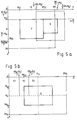
- the blocks R and S are assumed to have sizes M' x N' and Ms x Ns, respectively.
- Fig. 6b shows the overlap of the blocks R and S with respect to an input signal.
- the origin in the horizontal direction is located at the left end of the input signal of the block R for the sake of simplicity.
- the composite signal of the inverse-transformed signals of the blocks R and S is also attainable by use of the equation used to determine the composite signal of the blocks P and Q, if m, M, N, M Q and N Q are resplaced with m', M', N', Ms and Ns, respectively.
- the composite signal does not include horizontal reverse-order components.
- the equation (34.b) although it includes the term x R (m', N'-1-n), i.e., the vertical reverse-order components, the vertical reverse-order components are opposite in polarity to those of the composite signal of the blocks P and Q.
- the present invention is capable of reconstructing an input signal even when a bidimensional input signal is split into overlapping rectangular blocks each having a particular size.
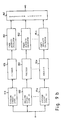
- the coding apparatus has a dividing circuit 1 and a linear transform circuit 2.
- the dividing circuit 1 divides a bidimensional input signal into a plurality of rectangular blocks each having a particular size while generating block division information.
- the linear transform circuit 2 calculates the transformed signals of M P x N P points by linear transform by use of 2M P x 2N P sampling points around the block of interest.
- the block information from the dividing circuit 1 and the transformed signal information from the linear transform circuit 2 are multiplexed by a multiplexer 5 and then sent to the decoding apparatus.
- the decoding apparatus has a linear transform circuit 3 and a synthesizing circuit 4 which overlays the signals of blocks.
- the linear transform circuit 3 calculates inverse-transformed signals of 2M P x 2N P points by linear transform on the basis of the transformed signal data and block information which are separated by a demultiplexer 6.
- the synthesizing circuit 4 arranges the inverse-transformed signals on the basis of the block information and, in portions where blocks overlap, adds the signals to produce a decoded signal.
- Figs. 8a and 8b each shows a specific manner of dividing a bidimensional input signal into blocks.
- a bidimensional signal is repetitively bisected in the horizontal and vertical directions a necessary number of times.
- Fig. 8b such a signal is divided into rectangular blocks each having a particular size.
- some different approaches are available, e.g., calculating the amounts of code of transformed signals and selecting particular division which makes the amounts of code minimum, and selecting division which makes the degree of power concentration on transformed signals representative of the intensities of lower frequency components maximum.
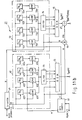
- Figs. 9a and 9b each shows a specific construction of circuitry for selecting a dividing method.
- the circuitry has n dividing circuits 911-91n, n encoders or linear transform circuits 921-92n, n coded signal amount calculators 931-93n, and a single decision circuit 941.
- the dividing circuits 911-91n each divides a bidimensional input signal by a particular dividing method.
- the encoders 921-92n each produces transformed signals with each of the blocks produced by the associated dividing circuit.
- the coded signal amount calculators 931-93n each calculates the amount of code of the transformed signal fed thereto from the associated encoder.
- the outputs of the coded signal amount calculators 931-93n are connected to the decision circuit 941.
- the decision circuit 941 compares one frame of bidimensional input signals derived from the respective dividing methods and outputs a selection signal indicative of one of the dividing methods which is smaller in the amount of coded signals than the others.
- the circuitry shown in Fig. 9b is identical with the circuitry of Fig. 9a except that the coded signal amount calculators 931-93n are replaced with power intensity calculators 951-95n.
- the circuitry of Fig. 9b selects one of the dividing methods which makes the power intensity on the lower frequencies of transformed signals maximum.
- Fig. 7 divides a bidimensional input signal into a plurality of blocks by using a particular method which is selected by the circuitry of Fig. 9a or 9b beforehand.
- the block information associated with each block e.g., a block size and a start point are coded, multiplexed with transformed signals and then sent to the decoding side since they are essential in the event of decoding.
- the division shown in Fig. 8a may be implemented with the coding method described in the previously stated Chen's paper. Specifically, as Chen shows in Fig. 2 of the paper, "1" is assigned to a given block when the block is divided into four subblocks, or "0" is assigned when it is not divided.
- the linear transform circuit 2, Fig. 7, may be implemented by M p x N p multiplying and adding circuits which, assuming that the predetermined maximum block size is M p x N p , weight and add the input signals of 2M p x 2N p points.
- Fig. 10a shows a specific construction of the linear transform circuit 2.
- the linear transform circuit 2 has M p x N p multiplying and adding circuits 10(1) - 10(M p x N p ) connected to an input signal line in parallel with each other, a block information decoder 15 for decoding block information to produce the size of a block of interest and the selection signal, and a selector 16 for selecting the output signal of one of the multiplying and adding circuits 10(1) -10(M p x N p ) in response to the selection signal.
- a window function generating circuit 17 generates window functions h AM (m) and h BN (n) on a direction and block size basis according to the block size and input signal coordinates.
- a first and a second multiplier 18 and 19 multiply the input signal x p (m, n) by the window functions h AM (m) and h BN (n), respectively.
- the multiplying and adding circuits 10(1) -10(M p x N p ) each has a coefficient memory 12, a multiplier 11, an accumulator 13, and an address generating circuit 14. Transform operations are as follows. Assume that a block of interest has the size M p x N p , i.e., the maximum block size. To transform such a block having the maximum block size, input signals at 2M p x 2N p points centering around the block are transformed, as stated previously.
- the transformed signal X p (m', n') (0 ⁇ m' ⁇ M p -1, 0 ⁇ n' ⁇ N p -1) of the input signal x p (m, n) (0 ⁇ m ⁇ 2M p -1, 0 ⁇ n ⁇ 2N p -1) is expressed as:
- h AM (m) and h BN (n) are multiplied by the input signal x p (m, n) by the multipliers 18 and 19, respectively.
- the coefficient memory 12(1) of the circuit 10(1) stores a coefficient matrix (assumed to be C 1 (m, n)) made up of 2M p x 2N p elements resulted from cos ⁇ (2m+M p +1) ⁇ /(4M p ) ⁇ x cos ⁇ (2n+N p +1) ⁇ /(4N p ) ⁇ (0 ⁇ m ⁇ 2M p -1, 0 ⁇ n ⁇ 2N p -1) as transform coefficients for blocks of the maximum size.
- a coefficient matrix (assumed to be C 1 (m, n)) made up of 2M p x 2N p elements resulted from cos ⁇ (2m+M p +1) ⁇ /(4M p ) ⁇ x cos ⁇ (2n+N p +1) ⁇ /(4N p ) ⁇ (0 ⁇ m ⁇ 2M p -1, 0 ⁇
- the coefficient memory 12(M p x N p ) of the "M p x N p " multiplying and adding circuit 10(M p x N p ) stores a coefficient matrix of 2M p x 2N p elements resulted from cos ⁇ (2m+M p +1) (2M p -1) ⁇ /(4M p ) ⁇ x cos ⁇ (2n+N p +1) (2N p -1) ⁇ /(4Np) ⁇ . It will be seen from the equation (3') that the coefficient changes with the block size. Hence, a plurality of coefficient matrixes each being assigned to a particular block size are stored in each coefficient memory.
- the address generating circuits 14(1) - 14(M p x N p ) each generates, in response to block size information from the block information decoder 15, the leading address of associated one of the coefficient memories 12(1) -12(M p x N p ) where a coefficient matrix matching the block size of interest is stored.
- a reading circuit not shown, sequentially reads in synchronism with the input signals the transform coefficients C 1 (m, n) associated with the block of maximum size out of the leading address having been designated by the address generating circuit 14(1).
- the multiplier 11(1) multiplies the window function-multiplied input signals x p (m, n) h AM (m) ⁇ h BN (n) by the transform coefficients C 1 (m, n).
- the accumulator 13(1) accumulates the results of multiplications to produce a transformed signal X p (0, 0).
- the other multiplying and adding circuits also perform similar operations in parallel. As a result, transformed signals X p (0,0) - X p (M p -1, N p -1) are obtained.
- the transformed signals X p (m', n') are sequentially selected by the selector 16 and fed therefrom to the multiplexer 5.
- the selection by the selector 16 is controlled by the selection signal which is generated by the block information decoder 15.
- the block information decoder 15 has, for example, a table listing the correspondence of the input signals of the selector 16 and the transformed signals X p (m', n') and controls the selector 16 in such a manner as to select only necessary ones of decoded block information.
- the decoder 15 generates a selection signal such that the selector 16 sequentially selects the output signals of all of the multiplying and adding circuits, the output signal X p (0, 0) of the circuit 10(1) being first, for example.
- the resulted transformed signals x p (m', n') are multiplexed with corresponding block information by the multiplexer 5, Fig. 7, and then transmitted to the decoding side.
- the window function generating circuit 17 will be described more specifically hereinafter.
- the present invention assigns different window functions on a direction and block size basis. Moreover, the values of window functions change from one region to another of the input signal, as described above. For this reason, the window function generating circuit 17 of the linear transform circuit 2 shown in Fig. 10a and located at the coding size generates window functions h AM (m) and h BN (n) in response to the input signal and block information.
- Fig. 11a shows a specific construction of the window function generating circuit 17. In Fig.
- the input signals x p (m, n) and the block information are applied to a data counter 51 and a separator 31, respectively.
- the data counter 51 counts the input signals x p (m, n) to produce the coordinates m and n of the input signals.
- the coordinate m in the horizontal direction and the coordinate n in the vertical direction are fed to a first region decision circuit 32 and a second region decision circuit 42, respectively.
- the separator 31 separates the block information from the block information decoder 15 into a horizontal block size M and a vertical block size N and transfers the resulted block sizes M and N to the decision circuits 32 and 42, respectively.
- the region decision circuit 32 has n threshold generating circuits 321-32n, n comparators 331-33n, and a counter 34.
- the threshold generating circuits 321-32n On receiving the horizontal block size M, the threshold generating circuits 321-32n generate corresponding n threshold values.
- the comparators 331-33n compare the horizontal coordinate m of the input signal with the n threshold values.
- the counter 34 receives the outputs of all of the comparators 331-33n to determine the number of comparators that have outputted a coincident output.
- the threshold generating circuits 321-32n determine, on the basis of the horizontal block size M, the value of horizontal coordinate m where the value of the window function h AM (m) corresponding to the block size changes.
- the window functions are configured as shown in Figs. 4a - 4c, four threshold values, i.e., (M/2-M 0 /2), (M/2 + M 0 /2), (3M/2 - M 0 /2) and (3M/2 + M 0 /2) are needed. Since the minimum block size in the horizontal direction is determined beforehand, the threshold values can be generated if the horizontal block size M is given.
- the number of threshold generating circuits may be determined in matching relation to the window function h AM (m) whose 5 maximum number changes.
- the comparators 331-33n compare the horizontal coordinate of the input signal from the data counter 51 with the threshold values from their associated threshold generating circuits 321-32n and generate a pulse when they are coincident.
- the output pulses of the comparators 331-33n are applied to the count terminals of the counter 34, so that the counter 34 outputs the number of input pulses.
- the number of pulses is indicative of a particular region to which the horizontal coordinate m of the input signal belongs.
- Fig. 12 tabulates a relation between the horizontal coordinate m of the input signal and the output of the counter 34.
- the counter 34 is assumed to be a 4-bit counter.
- a ROM 35 stores window functions h AM (m) assigned to the horizontal direction.
- the lower bits and the upper bits of the address terminal of the ROM 35 are allocated to the output of the counter 34 and the horizontal block size M, respectively. Consequently, a particular window function matching a block size is selected with the result that the value of the window function is changed in association with the horizontal coordinate of the input signal.
- Fig. 13 shows a specific relation between the address of the ROM 35 and the content thereof on the assumption that the window function h AM (m) has five different values depending on the horizontal coordinate of the input signal.
- the second region decision circuit 42 produces a window function h BN (n) matching a vertical block size of interest from a ROM 45 on the basis of the vertical block size N and the vertical coordinate n of the input signal.
- a counter 44 and the ROM 45 are respectively identical with the counter 34 and the ROM 35 except for the replacement of m, M, M 0 and h AM (m) with n, N, N 0 and h BN (n).
- Fig. 10b shows a specific construction of the linear transform circuit 3 which is substantially identical with the construction of Fig. 10a except for the number of multiplying and adding circuits 20(1) -20(2M p x2N p ).
- an inverse-transformed signal y (m, n) (0 ⁇ m ⁇ 2M p -1, 0 ⁇ n ⁇ 2N p -1) derived from a transformed signal X (m', n') (0 ⁇ m' ⁇ M p -1, 0 ⁇ n' ⁇ N p -1) is expressed as:
- a first and a second multiplier 28 and 29 multiply respectively the transformed signal x(m', n') by f AM (m) and f BN (n)/(MN) included in the above inverse transform equation.
- the coefficient memory 22(1) stores inverse-transform coefficients associated with the block of maximum size which are an inverse-transform coefficient matrix (assumed to be C 1 -1 (m', n')) of M p x N p elements represented by cos ⁇ (M p +1) (2m'+1) ⁇ /(4M p ) ⁇ x cos ⁇ (N p +1) (2n'+1) ⁇ /(4N p ) ⁇ (0 ⁇ m' ⁇ M p -1, 0 ⁇ n' ⁇ N p -1).
- the elements constituting the inverse-transform coefficient matrix C -1 2M p x 2N p (m', n') stored in the "2M p x 2N p " coefficient memory 22(2M p x 2N p ) and associated with the block of maximum size are represented by cos ⁇ (5M p -1) (2m'+1) ⁇ /(4M p ) ⁇ x cos ⁇ (5N p -1) (2n'+1) ⁇ /(4N p ) ⁇ (0 ⁇ m' ⁇ M p -1, 0 ⁇ n' ⁇ N p -1).
- the inverse-transform coefficients like the transform coefficients, change with the block size.
- the coefficient memories each stores a plurality of inverse-transform coefficient matrixes matching different block sizes.
- a block information decoder 25 and address generating circuits 24(1) - 24(2M p x2N p ) included in the multiplying and adding circuits cooperate to cause particular inverse-transform coefficient matrixes to be selected in matching relation to the block size.
- the selection principle is the same as with the coding linear transform circuit 2 and will not be described for simplicity.
- the inverse-transform coefficient matrix C -1 1 (m', n') selected out of the coefficient memory 22(1) by the address generating circuit 24(1) is sequentially read out in synchronism with the transform signals X p (m', n') under the control of a reading circuit, not shown, and multiplied by the multiplier 21(1).
- An accumulator 23(1) accumulates the results of multiplications to produce y p (0, 0).
- the other multiplying and summing circuits also perform such operations in parallel. As a result, y p (0, 0), y p (0, 1), ..., y p (2M p -1, 2N p -1) are obtained.
- a selector 26 sequentially selects the inverse-transformed signals y p (m, n) in response to selection signals from a block information decoder 25 and transfers them to the synthesizing circuit 4.
- Fig. 11b shows a specific construction of the window function generating circuit 27 shown in Fig. 10b.
- the circuitry shown in Fig. 11b is identical in construction and operation with the circuitry of Fig. 11a except for a multiplier 66 and a divider 67, and redundant description will be avoided for simplicity.
- the multiplier 66 and divider 67 are used to perform the division of the right member by the product of block sizes MN which occurs only in the inverse-transform equation (4) or (4').
- the multiplier 66 produces the product MN of horizontal and vertical block sizes M and N which a separator 61 outputs, while the divider 67 divides a vertical window function f BN (n) for decoding read out of a ROM 75 by the product MN, i.e., it produces f BN (n)/MN. While the specific construction of Fig. 11b divides the vertical window function f BN (n) by the product MN of block sizes, it may be modified to divide the horizontal window function f AM (n) or the division may be effected by any other section of the linear transform circuit 3, if the inverse-transform equation (4') can be executed.
- the circuit 4 has a block information decoder 91, a memory 93 whose capacity is great enough to accommodate one frame of bidimensional input signals, and an address generating circuit 92.
- the block information decoder 91 outputs block origin information in response to block information fed thereto from the demultiplexer 6.
- the address generating circuit 92 generates an address signal meant for the memory 93 in response to an inverse-transformed signal and block information.
- An adder 95 adds signal data read out of the memory 93 and being decoded and a inverse-transformed signal.
- a decoding controller 94 controls the reading and writing of data in the memory 93 while decoding is under way.
- a reading controller 96 controls the read-out of one frame of decoded signals associated with bidimensional input signals.
- the block information decoder 91 produces, in response to block information separated by the demultiplexer 6, Fig. 7, a transform-coded block size and the position of the origin of the block (assumed to be the upper left point) in an input signal frame (block origin coordinates).
- the address generating circuit 92 generates a particular address of the memory 93 for writing a transformed signal on the basis of block origin coordinates and block size.
- the memory 93 has an address space identical with the sampling points of one frame of bidimensional input signals and is used for temporary storage during the course of decoding operation.
- the decoding controller 94 On receiving the inverse-transformed signal y(m,n), the decoding controller 94 reads corresponding signal data being decoded out of the memory 93 within one sampling time of the inverse-transformed signal. Then, the decoding controller 94 writes in the same address the sum of the signal data and inverse-transformed signal which the adder 95 produces. As a result, inverse-transformed signals in a region where k blocks overlap are added k times.
- the decoding controller 94 When the frame of input signals changes, the decoding controller 94 generates an end-of-decode signal to inform the reading controller 96 of the end of decoding. To detect the change of frame, a frame pulse usually included in a picture signal may be detected.
- the reading controller 96 In response to the end-of-decode signal, the reading controller 96 reads data out of the reading address of the memory 93 and sequentially outputs them as a decoded signal. On reading out all the data, the reading controller 96 resets the contents of the memory 93.
- the present invention produces correct decoded signals even when a bidimensional input signal is divided into blocks each having a particular block size and overlapping the others.
- the window functions h AMO (m), h BNO (n), f AMO (m) and f BNO (n) for the block of the minimum size may be implemented as the window function represented by the equation 9 of the previously stated H. Schiller's paper or the window function shown in table 1 of J.P. Princen et al "Analysis/Synthesis Filter Bank Design Based on Time Domain Aliasing Cancellation", IEEE Transactions on Acoustics, Speech, and Signal Processing, Vol. 34, No. 5, October 1986, pp.
- h AM (m), h BN (n), f AM (m) and f BN (n) for block sizes other than the minimum block size, assuming in the equations (7.a) - (7.n) then This is successful in reconstructing, when a transformed signal with no artifacts is decoded, an input signal in the decoded signal.
- the window functions may be changed in matching relation to the size of the block adjoining the block of interest.
- blocks neighboring the block of interest are of 16 x 16 size
- the present invention produces a decoded signal by adding the inverse-transformed signals of nearby blocks. This not only reduces block boundary artifacts but also allows the block size to be changed in matching relation to the characteristic of a signal.
- the present invention therefore, achieves extremely efficient coding by selecting a comparatively large block size in, for example, an area occupied by the same pattern or a comparatively small block size in, for example, an area where the characteristic of the signal sharply changes.
- Another advantage attainable with the present invention is that the number of sampling points of a signal to be transmitted is the same as that of an input signal.
Landscapes
- Engineering & Computer Science (AREA)
- Multimedia (AREA)
- Signal Processing (AREA)
- Compression Or Coding Systems Of Tv Signals (AREA)
- Compression, Expansion, Code Conversion, And Decoders (AREA)
Claims (3)
- Verfahren zum Kodieren und Dekodieren eines zweidimensionalen Bildsignals mit den Schritten:
auf einer Kodierungsseite(a) Unterteilen eines zweidimensionalen Eingangssignals in rechteckige Blöcke mehrerer Abmessungen gemäß einer Block-Unterteilungsinformation;(b) Bereitstellen von Fensterfunktionen hAM(m) und hBN(n) auf einer Richtungs- und Blockabmessungsbasis;(c) Berechnen unter der Annahme, daß ein interessierender Block eine Abmessung von M x N aufweist, von transformierten Signalen Xp (k, i) aus Eingangssignalen xp (m, n) (m = 0, 1, ...., 2M-1; n = 0, 1, ...., 2N-1) mittels einer Transformationsgleichung: (d) Übertragen der Block-Unterteilungsinformation und der transformierten Signale auf eine Dekodierungsseite;auf der Dekodierungsseite:(e) Bereitstellen von Fensterfunktionen fAM(m) und fBN(n), die den Fensterfunktionen hAM(m) bzw. hBN(n) entsprechen;(f) Berechnen, wenn eine Blockabmessung der von der Kodierungsseite gesendeten transformierte Signale gleich M x N ist, von invers-transformierten Signalen yp(m, n) mit 2M x 2N Punkten aus den transformierten Signalen mittels einer Transformationsgleichung:
 (g) Anordnen der invers-transformierten Signale gemäß der von der Kodierungsseite gesendeten Block-Unterteilungsinformation; und(h) Addieren der invers-transformierten Signale in einem Bereich, wo sich mehrere Blöcke überlappen, um ein dekodiertes Signal zu erzeugen.
 - Vorrichtung zum Kodieren eines zweidimensionalen Bildsignals mit:einer Einrichtung zum Unterteilen eines zweidimensionalen Eingangssignals in rechteckige Blöcke mehrerer Abmessungen gemäß einer Block-Unterteilungsinformation; undeiner Einrichtung mit Fensterfunktionen hAM(m) und hBN(n) auf einer Richtungs- und Blockabmessungsbasis zum Berechnen, wenn ein interessierender Block eine Abmessung von M x N aufweist, von transformierten Signalen Xp(k, i) von M x N Punkten aus Eingangssignalen xp(m, n) (m = 0, 1, ...., 2M-1; n = 0, 1, ...., 2N-1) von 2M x 2N Punkten mittig um den interessierenden Block mittels einer Transformationsgleichung:

- Vorrichtung zum Dekodieren eines zweidimensionalen Bildsignals, welches auf einer Kodierungsseite durch eine Kodierungsvorrichtung nach Anspruch 2 erzeugt wurde, wobei die Vorrichtung aufweist:eine Einrichtung mit Fensterfunktionen fAM(m) und fBN(n), die den in Anspruch 2 genannten Fensterfunktionen hAM(m) bzw. hBN(n) entsprechen, zum Berechnen, wenn transformierte Signale von der Kodierungsseite eine Blockabmessung von M x N aufweisen, von invers-transformierten Signalen yp(m, n) mit 2M x 2N Punkten aus eingegebenen transformierten Signalen Xp(k, i) mittels einer Transformationsgleichung:
 und eine Einrichtung zum Anordnen der invers-transformierten Signale yp(m, n) gemäß der von der Kodierungsseite gesendeten Block-Unterteilungsinformation und zum Addieren der invers-transformierten Signale in einem Bereich, wo sich mehrere Blöcke überlappen, um ein dekodiertes Signal zu erzeugen.
Applications Claiming Priority (2)
| Application Number | Priority Date | Filing Date | Title |
|---|---|---|---|
| JP135272/90 | 1990-05-28 | ||
| JP13527290A JP2639176B2 (ja) | 1990-05-28 | 1990-05-28 | 2次元信号符号化復号化方法とその符号化装置・復号化装置 |
Publications (3)
| Publication Number | Publication Date |
|---|---|
| EP0467054A2 EP0467054A2 (de) | 1992-01-22 |
| EP0467054A3 EP0467054A3 (en) | 1993-05-05 |
| EP0467054B1 true EP0467054B1 (de) | 1996-08-21 |
Family
ID=15147826
Family Applications (1)
| Application Number | Title | Priority Date | Filing Date |
|---|---|---|---|
| EP19910108684 Expired - Lifetime EP0467054B1 (de) | 1990-05-28 | 1991-05-28 | Kodier- und Dekodierverfahren für ein Bildsignal unter Verwendung von überlappenden Blöcken mit variablen Abmessungen und Vorrichtung dazu |
Country Status (4)
| Country | Link |
|---|---|
| EP (1) | EP0467054B1 (de) |
| JP (1) | JP2639176B2 (de) |
| CA (1) | CA2043397C (de) |
| DE (1) | DE69121487T2 (de) |
Cited By (3)
| Publication number | Priority date | Publication date | Assignee | Title |
|---|---|---|---|---|
| US7471726B2 (en) | 2003-07-15 | 2008-12-30 | Microsoft Corporation | Spatial-domain lapped transform in digital media compression |
| US7551789B2 (en) | 2004-12-17 | 2009-06-23 | Microsoft Corporation | Reversible overlap operator for efficient lossless data compression |
| US8036274B2 (en) | 2005-08-12 | 2011-10-11 | Microsoft Corporation | SIMD lapped transform-based digital media encoding/decoding |
Families Citing this family (7)
| Publication number | Priority date | Publication date | Assignee | Title |
|---|---|---|---|---|
| US5335017A (en) * | 1993-01-08 | 1994-08-02 | Scott C. Harris | Method for encoding transmitting and receiving high definition television signals using single variable independent equations representing each pixel over time |
| DE4418782C2 (de) * | 1993-05-21 | 1997-01-09 | Mitsubishi Electric Corp | System und Verfahren zum Einstellen eines Farbbildes |
| US5629778A (en) * | 1995-05-15 | 1997-05-13 | Polaroid Corporation | Method and apparatus for reduction of image data compression noise |
| DE10022331A1 (de) * | 2000-05-10 | 2001-11-15 | Bosch Gmbh Robert | Verfahren zur Transformationscodierung von Bewegtbildsequenzen |
| JP4556694B2 (ja) * | 2005-02-07 | 2010-10-06 | ソニー株式会社 | 符号化装置および方法、記録媒体、プログラム、並びに画像処理システム |
| US8369638B2 (en) | 2008-05-27 | 2013-02-05 | Microsoft Corporation | Reducing DC leakage in HD photo transform |
| US8275209B2 (en) | 2008-10-10 | 2012-09-25 | Microsoft Corporation | Reduced DC gain mismatch and DC leakage in overlap transform processing |
Family Cites Families (1)
| Publication number | Priority date | Publication date | Assignee | Title |
|---|---|---|---|---|
| JPH01227590A (ja) * | 1988-03-07 | 1989-09-11 | Victor Co Of Japan Ltd | デジタル画像データの圧縮伸長方式 |
-
1990
- 1990-05-28 JP JP13527290A patent/JP2639176B2/ja not_active Expired - Lifetime
-
1991
- 1991-05-28 DE DE69121487T patent/DE69121487T2/de not_active Expired - Fee Related
- 1991-05-28 EP EP19910108684 patent/EP0467054B1/de not_active Expired - Lifetime
- 1991-05-28 CA CA 2043397 patent/CA2043397C/en not_active Expired - Fee Related
Cited By (3)
| Publication number | Priority date | Publication date | Assignee | Title |
|---|---|---|---|---|
| US7471726B2 (en) | 2003-07-15 | 2008-12-30 | Microsoft Corporation | Spatial-domain lapped transform in digital media compression |
| US7551789B2 (en) | 2004-12-17 | 2009-06-23 | Microsoft Corporation | Reversible overlap operator for efficient lossless data compression |
| US8036274B2 (en) | 2005-08-12 | 2011-10-11 | Microsoft Corporation | SIMD lapped transform-based digital media encoding/decoding |
Also Published As
| Publication number | Publication date |
|---|---|
| DE69121487T2 (de) | 1997-01-09 |
| DE69121487D1 (de) | 1996-09-26 |
| EP0467054A3 (en) | 1993-05-05 |
| EP0467054A2 (de) | 1992-01-22 |
| JP2639176B2 (ja) | 1997-08-06 |
| JPH0435269A (ja) | 1992-02-06 |
| CA2043397C (en) | 1996-01-16 |
| CA2043397A1 (en) | 1991-11-29 |
Similar Documents
| Publication | Publication Date | Title |
|---|---|---|
| EP0227439B1 (de) | Verfahren und Vorrichtung für die Übermittlung von digitalen Daten und Vorrichtung zum Dekodieren von digitalen Daten | |
| EP0260139B1 (de) | Bildverarbeitung | |
| US5189526A (en) | Method and apparatus for performing image compression using discrete cosine transform | |
| US4791486A (en) | Recursive image encoding/decoding using interpolation within variably sub-divided picture areas | |
| US5901242A (en) | Method and apparatus for decoding spatiochromatically multiplexed color images using predetermined coefficients | |
| US4918527A (en) | Device and method with buffer memory, particularly for line/column matrix transposition of data sequences | |
| US6157676A (en) | Digital video signal inter-block interpolative predictive encoding/decoding apparatus and method providing high efficiency of encoding | |
| KR100289592B1 (ko) | 디지털 영상 신호에 대한 계층 엔코딩 및 디코딩장치 | |
| US5757973A (en) | Compression of image data seperated into frequency component data in a two dimensional spatial frequency domain | |
| EP0450937B1 (de) | Geometrische Vektorquantifizierung | |
| EP0944961B1 (de) | Verschachtelte verteilte kodierung von spärlich bestückten datensätzen | |
| EP1750448A2 (de) | Bildcodierer und -decodierer | |
| EP0467054B1 (de) | Kodier- und Dekodierverfahren für ein Bildsignal unter Verwendung von überlappenden Blöcken mit variablen Abmessungen und Vorrichtung dazu | |
| US6002809A (en) | Digital image processor for image scaling | |
| JPH05507600A (ja) | ビデオ信号の圧縮 | |
| GB1535011A (en) | Method and arrangement for redundancy-reducing picture coding | |
| US5590222A (en) | Image signal processing apparatus utilizing a 2D Haar transform and adaptive selection of images based on a parameter such as a ratio of coefficients for reducing block distortion and method thereof | |
| US5343539A (en) | Method for spatial domain image compression | |
| EP0454234B1 (de) | Verarbeitung von Bildsignalen | |
| JPH04247770A (ja) | 画像データ圧縮方法および画像データ圧縮装置ならびに画像データ復元装置 | |
| JPH0888849A (ja) | 画像信号処理方法及び画像信号伝送装置 | |
| WO1991019272A1 (en) | Improved image compression system | |
| Farrelle et al. | Quad-tree based two source image coding | |
| JPH04271664A (ja) | 画像データ圧縮装置および画像データ復元装置 | |
| Kiselyov | Multiresolutional/fractal compression of still and moving pictures |
Legal Events
| Date | Code | Title | Description |
|---|---|---|---|
| PUAI | Public reference made under article 153(3) epc to a published international application that has entered the european phase |
Free format text: ORIGINAL CODE: 0009012 |
|
| 17P | Request for examination filed |
Effective date: 19910626 |
|
| AK | Designated contracting states |
Kind code of ref document: A2 Designated state(s): DE FR GB |
|
| PUAL | Search report despatched |
Free format text: ORIGINAL CODE: 0009013 |
|
| AK | Designated contracting states |
Kind code of ref document: A3 Designated state(s): DE FR GB |
|
| 17Q | First examination report despatched |
Effective date: 19950530 |
|
| GRAH | Despatch of communication of intention to grant a patent |
Free format text: ORIGINAL CODE: EPIDOS IGRA |
|
| GRAA | (expected) grant |
Free format text: ORIGINAL CODE: 0009210 |
|
| GRAH | Despatch of communication of intention to grant a patent |
Free format text: ORIGINAL CODE: EPIDOS IGRA |
|
| AK | Designated contracting states |
Kind code of ref document: B1 Designated state(s): DE FR GB |
|
| REF | Corresponds to: |
Ref document number: 69121487 Country of ref document: DE Date of ref document: 19960926 |
|
| ET | Fr: translation filed | ||
| PG25 | Lapsed in a contracting state [announced via postgrant information from national office to epo] |
Ref country code: GB Effective date: 19970528 |
|
| PLBE | No opposition filed within time limit |
Free format text: ORIGINAL CODE: 0009261 |
|
| STAA | Information on the status of an ep patent application or granted ep patent |
Free format text: STATUS: NO OPPOSITION FILED WITHIN TIME LIMIT |
|
| 26N | No opposition filed | ||
| GBPC | Gb: european patent ceased through non-payment of renewal fee |
Effective date: 19970528 |
|
| PG25 | Lapsed in a contracting state [announced via postgrant information from national office to epo] |
Ref country code: FR Free format text: LAPSE BECAUSE OF NON-PAYMENT OF DUE FEES Effective date: 19980130 |
|
| PG25 | Lapsed in a contracting state [announced via postgrant information from national office to epo] |
Ref country code: DE Free format text: LAPSE BECAUSE OF NON-PAYMENT OF DUE FEES Effective date: 19980203 |
|
| REG | Reference to a national code |
Ref country code: FR Ref legal event code: ST |