EP0227458B1 - "Diversity"-Empfänger - Google Patents
"Diversity"-Empfänger Download PDFInfo
- Publication number
- EP0227458B1 EP0227458B1 EP86309993A EP86309993A EP0227458B1 EP 0227458 B1 EP0227458 B1 EP 0227458B1 EP 86309993 A EP86309993 A EP 86309993A EP 86309993 A EP86309993 A EP 86309993A EP 0227458 B1 EP0227458 B1 EP 0227458B1
- Authority
- EP
- European Patent Office
- Prior art keywords
- electric field
- power source
- receiver
- receivers
- switch
- Prior art date
- Legal status (The legal status is an assumption and is not a legal conclusion. Google has not performed a legal analysis and makes no representation as to the accuracy of the status listed.)
- Expired - Lifetime
Links
- 230000005684 electric field Effects 0.000 claims description 58
- 238000001514 detection method Methods 0.000 claims description 35
- 238000012935 Averaging Methods 0.000 claims description 3
- 238000001914 filtration Methods 0.000 claims 1
- 238000010586 diagram Methods 0.000 description 9
- 238000004891 communication Methods 0.000 description 8
- 238000007796 conventional method Methods 0.000 description 3
- 230000015556 catabolic process Effects 0.000 description 2
- 238000006731 degradation reaction Methods 0.000 description 2
- 230000003247 decreasing effect Effects 0.000 description 1
- 238000005562 fading Methods 0.000 description 1
Images



Classifications
-
- H—ELECTRICITY
- H04—ELECTRIC COMMUNICATION TECHNIQUE
- H04B—TRANSMISSION
- H04B1/00—Details of transmission systems, not covered by a single one of groups H04B3/00 - H04B13/00; Details of transmission systems not characterised by the medium used for transmission
- H04B1/06—Receivers
- H04B1/16—Circuits
- H04B1/1607—Supply circuits
- H04B1/1615—Switching on; Switching off, e.g. remotely
-
- H—ELECTRICITY
- H04—ELECTRIC COMMUNICATION TECHNIQUE
- H04B—TRANSMISSION
- H04B7/00—Radio transmission systems, i.e. using radiation field
- H04B7/02—Diversity systems; Multi-antenna system, i.e. transmission or reception using multiple antennas
- H04B7/04—Diversity systems; Multi-antenna system, i.e. transmission or reception using multiple antennas using two or more spaced independent antennas
- H04B7/08—Diversity systems; Multi-antenna system, i.e. transmission or reception using multiple antennas using two or more spaced independent antennas at the receiving station
- H04B7/0802—Diversity systems; Multi-antenna system, i.e. transmission or reception using multiple antennas using two or more spaced independent antennas at the receiving station using antenna selection
- H04B7/0817—Diversity systems; Multi-antenna system, i.e. transmission or reception using multiple antennas using two or more spaced independent antennas at the receiving station using antenna selection with multiple receivers and antenna path selection
- H04B7/082—Diversity systems; Multi-antenna system, i.e. transmission or reception using multiple antennas using two or more spaced independent antennas at the receiving station using antenna selection with multiple receivers and antenna path selection selecting best antenna path
-
- H—ELECTRICITY
- H04—ELECTRIC COMMUNICATION TECHNIQUE
- H04L—TRANSMISSION OF DIGITAL INFORMATION, e.g. TELEGRAPHIC COMMUNICATION
- H04L1/00—Arrangements for detecting or preventing errors in the information received
- H04L1/0001—Systems modifying transmission characteristics according to link quality, e.g. power backoff
-
- H—ELECTRICITY
- H04—ELECTRIC COMMUNICATION TECHNIQUE
- H04W—WIRELESS COMMUNICATION NETWORKS
- H04W52/00—Power management, e.g. Transmission Power Control [TPC] or power classes
- H04W52/02—Power saving arrangements
- H04W52/0209—Power saving arrangements in terminal devices
- H04W52/0225—Power saving arrangements in terminal devices using monitoring of external events, e.g. the presence of a signal
- H04W52/0245—Power saving arrangements in terminal devices using monitoring of external events, e.g. the presence of a signal according to signal strength
-
- Y—GENERAL TAGGING OF NEW TECHNOLOGICAL DEVELOPMENTS; GENERAL TAGGING OF CROSS-SECTIONAL TECHNOLOGIES SPANNING OVER SEVERAL SECTIONS OF THE IPC; TECHNICAL SUBJECTS COVERED BY FORMER USPC CROSS-REFERENCE ART COLLECTIONS [XRACs] AND DIGESTS
- Y02—TECHNOLOGIES OR APPLICATIONS FOR MITIGATION OR ADAPTATION AGAINST CLIMATE CHANGE
- Y02D—CLIMATE CHANGE MITIGATION TECHNOLOGIES IN INFORMATION AND COMMUNICATION TECHNOLOGIES [ICT], I.E. INFORMATION AND COMMUNICATION TECHNOLOGIES AIMING AT THE REDUCTION OF THEIR OWN ENERGY USE
- Y02D30/00—Reducing energy consumption in communication networks
- Y02D30/70—Reducing energy consumption in communication networks in wireless communication networks
Definitions
- the present invention relates to a diversity receiver and, more particularly, to a diversity receiver which has two receivers and performs selective switching between demodulated outputs from the two receivers.
- a selection diversity-type receiver has two receivers which generate electric field detection outputs in accordance with the intensity of the received electric field.
- the receiver compares the electric field detection outputs from the two receivers while the two receivers are constantly ON, and performs switching in order to select a demodulated output from a receiver having a higher electric field detection output.
- a system of this type is illustrated by the PATENT ABSTRACT OF JAPAN, vol.9 no. 251 (E-348) [1974], 8th October 1985.
- any of a plurality of antennas is connected to a single receiver.
- the quality of communication of the selected antenna is degraded below a predetermined value, it is switched to another antenna, thereby restoring predetermined quality of communication. Since only a single receiver is provided, power consumption is small. However, quality of communication is not improved as much as in the selection diversity-type receiver.
- the diversity receiver comprises: first and second receivers having receiver antennas and generating demodulated signals and electric field detection outputs in accordance with received electric fields, respectively; a first switch for switching between the demodulated signals from the first and second receivers in accordance with an output switching control signal and outputting a selected one of the demodulated signals; comparing means for comparing the electric field detection outputs from the first and second receivers, respectively, and supplying the output switching control signal to the first switch in accordance with the result of the comparison; a second switch for turning on/off a power supply source of the first receiver in accordance with a power source switching control signal; and a controller for receiving the electric field detection output from the second receiver, averaging intensity of the received electric field, and supplying the power source switching control signal to the second switch in accordance with the average intensity of the electric field.
- Fig. 1 is a block diagram of a selection diversity receiver according to an embodiment of the present invention.
- reference numerals 1 and 2 denote antennas; 3 and 4, receivers; 5, a comparator; 6 and 7, switches; 8, a controller; 9, a low frequency amplifier; and 10, a loudspeaker.
- the signals received by the antennas 1 and 2 are amplified and demodulated by the receivers 3 and 4, respectively.
- Electric field detection outputs V1 and V2 generated by the receivers 3 and 4 are compared with each other by the comparator 5, and the switch 6 is switched so that the demodulated output of the receiver whose electric field detection output voltage is higher than the other is selected.
- the demodulated output selected by the switch 6 is amplified by the low frequency amplifier 9 and output from the loudspeaker 10.
- the electric field detection output V2 from the receiver 4 is also supplied to the controller 8.
- the controller 8 averages the voltages of the electric field detection output V2 to obtain an average electric field detection output voltage, and compares it with a predetermined reference voltage. Also, the controller 8 generates a control signal to turn off the switch 7 when the average electric field detection output voltage is higher than the reference voltage, and to turn on the switch 7 when the average electric field detection output voltage is lower than the reference voltage.
- the switch 7 is turned on, diversity signal reception is performed.
- the switch 7 is turned off, the electric field detection output V1 of the receiver 3 becomes 0 and the comparator 4 constantly selects the demodulated signal from the receiver 4.
- Fig. 2 is a circuit diagram showing in detail an example of the controller 8.
- the electric field detection output V2 When the electric field detection output V2 is supplied from the receiver 4 to the controller 8, it is integrated by a low pass filter 11 to obtain an average electric field detection output voltage Va which is input to the inverting input terminal of a comparator 12.
- the non-inverting input terminal of the comparator 12 receives a reference voltage Vr obtained by dividing a power source voltage Vcc by resistors 13 and 14.
- the comparator 12 outputs a signal of high level "H” and turns on the switch 7.
- the comparator 12 When the average electric field detection output voltage Va is larger than the reference voltage Vr, the comparator 12 outputs a signal of low level "L” and turns off the switch 7.
- the power source for the first receiver is turned off and reception is performed only by the second receiver. Therefore, the power consumption is reduced.
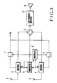
- Fig. 3 is a block diagram of a diversity receiver according to another embodiment of the present invention.
- FIG. 3 This embodiment is different from that of Fig. 1 in the following points. Particularly, in Fig. 3, outputs V1 and V2 from receivers 3 and 4 are supplied to a controller 8 ⁇ . A power source voltage Vcc for the receiver 4 is supplied through a switch 1 which is controlled by the controller 8 ⁇ .
- the signals received by the antennas 1 and 2 are amplified and demodulated by the receivers 3 and 4, respectively.
- Electric field detection outputs V1 and V2 generated by the receivers 3 and 4 are compared with each other by a comparator 5, and a switch 6 is switched so that the demodulated output of the receiver whose electric field detection output is higher than the other is selected.
- the demodulated output selected by the switch 6 is amplified by a low frequency amplifier 9 and output from a loudspeaker 10.
- the electric field detection outputs V1 and V2 from the receivers 3 and 4 are supplied to the controller 8 ⁇ .
- the controller 8 ⁇ averages the voltages of the electric field detection outputs V1 and V2 to obtain average electric field detection outputs V1 and V2, respectively, and compares them with a preset reference voltage Vr.
- Fig. 4 shows an example of the controller 8 ⁇ for practicing the above operation.
- reference numerals 21 and 22 denote low pass filter; 23, 24, and 25, comparators; 26, an inverter; 27, a NOR gate; 28, an exclusive OR gate; 29 to 33, AND gates; and 34 and 35, OR gates.
- the outputs from the low pass filters 21 and 22 respectively correspond to V 1 and V 2 obtained by averaging their input voltages V1 and V2 over time.
- the comparators 23, 24 and 25 respectively compare V 1 with the reference voltage Vr, V 1 with V 2, and V 2 with Vr.
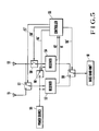
- Fig. 5 is a block diagram of still another embodiment of the present invention.
- Either an antenna 51 or 52 is connected to a receiver 53 through a switch 57.
- the antenna 52 and a receiver 54 are connected to each other through a switch 58.
- a demodulated output from either the receiver 53 or 54 is connected to a base band unit 61 through a switch 59.
- a controller 55 receives received electric field detection outputs V1 and V2 from the receivers 53 and 54, respectively, and calculates an average electric field intensity within a predetermined period of time.
- the controller 55 controls switches 57, 58, 59, and 60 through control lines 57 ⁇ , 58 ⁇ , 59 ⁇ , and 60 ⁇ in order to perform an antenna switching diversity operation when the average intensity of the electric field is higher than a predetermined value, and to perform a selective diversity operation when the average intensity of the electric field is lower than the predetermined value.
- the switch 58 is turned off, the switch 59 connects the receiver 53 with the base band unit 61, and the switch 60 disconnects a power source 56 and the receiver 54.
- the switch 57 is controlled to switch to another antenna.
- the switch 57 connects the antenna 51 with the receiver 53, the switch 58 connects the antenna 52 with the receiver 54, and the switch 60 is turned on.
- the controller 55 controls the switch 59 so that a larger received electric field detection output of the two outputs from the receivers 3 and 4 is connected to the base band unit 61.
- Fig. 6 is a graph showing the relationship between the intensity of the electric field and the quality of communication in the embodiment of Fig. 5 in comparison with that in the case of a conventional technique.
- broken lines A, B, and C indicate the cases of selective diversity, antenna switching diversity, and reception without diversity, respectively
- a solid line D indicates the case of the present invention.
- reference symbol a indicates an average intensity of electric field for switching between antenna switching and selective diversity operations.
- Fig. 6 generally when the intensity of electric field is low, degradation in quality of communication is considerable.
- both antenna switching and selective diversity operations are employed, even if the intensity of the electric field is low, a higher quality of communication can be maintained compared with a case of an antenna switching diversity receiver.
- Fig. 7 is a graph showing the relationship between the intensity of the electric field and the power consumption in the embodiment of Fig. 5 in comparison with that in the case of the conventional technique.
- broken lines E and F indicate cases of selective and antenna switching diversity operations, respectively, and a solid line E indicates the case of the present embodiment. In this manner, according to the present invention, the power consumption can be decreased below that of a selective diversity receiver.
Landscapes
- Engineering & Computer Science (AREA)
- Computer Networks & Wireless Communication (AREA)
- Signal Processing (AREA)
- Quality & Reliability (AREA)
- Radio Transmission System (AREA)
Claims (5)
- Diversityempfänger mit:
ersten und zweiten Empfängern (3, 4) mit Empfängerantennen (1, 2), die demodulierte Signale und Erkennungssignale für die elektrischen Felder entsprechend den empfangenen elektrischen Feldern erzeugen;
einem ersten Schalter (6), um die demodulierten Signale von den ersten und zweiten Empfängern (3, 4) entsprechend einem Ausgangsschaltsteuersignal zu schalten und ein ausgewähltes der demodulierten Signale auszugeben; und
einer Komparatoreinrichtung (5), um die Ausgänge der Erkennungssignale für die elektrischen Felder von den ersten bzw. zweiten Empfängern (3, 4) zu vergleichen und das Ausgangsschaltsteuersignal zu dem ersten Schalter (6) entsprechend dem Ergebnis des Vergleichs zu liefern,
gekennzeichnet durch:
einen zweiten Schalter (7), um eine Stromversorgungsquelle für den ersten Empfänger (3) entsprechend einem Stromquellenschaltsteuersignal ein/auszuschalten; und
einen Regler (8), um den Ausgang der elektrischen Feldfeststellung von dem zweiten Empfänger (4) zu empfangen, die Intensität des empfangenen elektrischen Feldes zu mitteln und das Stromquellenschaltsteuersignal zu dem zweiten Schalter (7) in Übereinstimmung mit der mittleren Intensität des elektrischen Feldes zu liefern. - Diversityempfänger nach Anspruch 1, wobei der Regler (8) einen Tiefpaßfilter (11) zum Filtern des Erkennungssignals für das elektrische Feld aus dem zweiten Empfänger (4) und einen Komparator (12) aufweist, um einen Ausgang aus dem Tiefpaßfilter (11) mit einer vorbestimmten Referenzspannung zu vergleichen und das Stromquellenschaltsignal auszugeben.
- Diversityempfänger mit:
ersten und zweiten Empfängern (3, 4) mit Empfangsantennen (1, 2), die demodulierte Signale und Erkennungssignale für die elektrischen Felder entsprechend den empfangenen elektrischen Feldern erzeugen;
einem ersten Schalter (6), um die demodulierten Signale von den ersten und zweiten Empfängern (3, 4) entsprechend einem Ausgangsschaltsteuersignal zu schalten und ein ausgewähltes der demodulierten Signale auszugeben; und
einer Komparatoreinrichtung (5), um die Erkennungssignale für die elektrischen Felder aus den ersten bzw. zweiten Empfängern (3, 4) zu vergleichen und das Ausgangsschaltsteuersignal zu dem ersten Schalter (6) entsprechend dem Ergebnis des Vergleichs zu liefern,
gekennzeichnet durch:
erste und zweite Stromquellenschalter (7, 11), um eine Stromquelle (Vcc) für die ersten und zweiten Empfänger (3, 4) entsprechend den ersten und zweiten Stromquellen-Schaltsteuersignalen ein/auszuschalten; und
einen Regler (8'), um die Erkennungssignale für die elektrischen Felder aus den ersten und zweiten Empfängern (3, 4) zu empfangen und die ersten und zweiten Stromquellenschaltsteuersignale zu den ersten und zweiten Stromquellenschaltern (7, 11) entsprechend den Größen der Erkennungssignale für die elektrischen Felder zu liefern. - Diversityempfänger nach Anspruch 3, wobei der Regler (8') aufweist:
erste und zweite Tiefpaßfilter (21, 22), um mittlere Spannungen V1 und V2 der Erkennungssignale für die elektrischen Felder aus den ersten bzw. zweiten Empfängern (3, 4) zu erzeugen;
erste und zweite Komparatoren (23, 25), um die Ausgänge aus den ersten und zweiten Tiefpaßfiltern (21, 22) mit einer Referenzspannung Vr zu vergleichen;
einen dritten Komparator (24), um die Ausgänge der ersten und zweiten Tiefpaßfilter miteinander zu vergleichen; und
einen Logikschaltkreis (26 bis 35), um(1) die ersten und zweiten Stromquellenschalter (7, 11) einzuschalten und die selektive Diversityoperation auszuführen, wenn V1 < Vr und V2 < Vr ist,(2) die ersten und zweiten Stromquellenschalter (7, 11) entsprechend aus- und einzuschalten, wenn V1 < Vr und V2 > Vr ist,(3) die ersten bzw. zweiten Stromquellenschalter (7, 11) ein- und auszuschalten, wenn V1 > Vr und V2< Vr ist, und(4) V1 mit V2 zu vergleichen, wenn V1 > Vr und V2 > Vr ist, unddie ersten bzw. zweiten Stromquellenschalter (7, 11) ein- und auszuschalten, wenn V1 > V2 ist, und
die ersten bzw. zweiten Stromquellenschalter (7, 11) aus- und einzuschalten, wenn V1 < V2. - Diversityempfänger mit:
ersten und zweiten Antennen (51, 52);
ersten und zweiten Empfängern (53, 54); um die empfangenen Wellen von den ersten bzw. zweiten Antennen (51, 52) zu verstärken und zu demodulieren und die Intensitäten der empfangenen elektrischen Felder festzustellen und auszugeben; und
einem Ausgangsschaltungs-Schalter (59), um einen der Ausgänge aus den ersten und zweiten Empfängern (53, 54) in Übereinstimmung mit einem Ausgangsschaltsteuersignal auszugeben;
gekennzeichnet durch:
einen ersten Eingangsschalter (57), um die erste oder zweite Antenne (51 oder 52) auszuwählen und die ausgewählte Antenne mit dem ersten Empfänger (53) zu verbinden;
einen zweiten Eingangsschalter (58), um die Verbindung zwischen der zweiten Antenne (52) und dem zweiten Empfänger (54) ein/auszuschalten;
einen Stromquellenschalter (60), um eine Stromquelle des zweiten Empfängers (54) ein/auszuschalten; und
einen Regler (55), um die Intensitätsausgangssignale für die empfangenen elektrischen Felder aus den ersten und zweiten Empfängern (53, 54) zu empfangen und die ersten und zweiten Eingangsschalter (57, 58) und den Stromquellenschalter (60) entsprechend den Größen der Intensitätsausgangssignale der empfangenen elektrischen Felder Ein/Aus zu steuern.
Applications Claiming Priority (2)
| Application Number | Priority Date | Filing Date | Title |
|---|---|---|---|
| JP289832/85 | 1985-12-23 | ||
| JP28983285 | 1985-12-23 |
Publications (3)
| Publication Number | Publication Date |
|---|---|
| EP0227458A2 EP0227458A2 (de) | 1987-07-01 |
| EP0227458A3 EP0227458A3 (en) | 1988-10-19 |
| EP0227458B1 true EP0227458B1 (de) | 1992-04-08 |
Family
ID=17748345
Family Applications (1)
| Application Number | Title | Priority Date | Filing Date |
|---|---|---|---|
| EP86309993A Expired - Lifetime EP0227458B1 (de) | 1985-12-23 | 1986-12-22 | "Diversity"-Empfänger |
Country Status (8)
| Country | Link |
|---|---|
| US (1) | US4823398A (de) |
| EP (1) | EP0227458B1 (de) |
| JP (1) | JPS62230125A (de) |
| AU (1) | AU589859B2 (de) |
| CA (1) | CA1281079C (de) |
| DE (1) | DE3684769D1 (de) |
| HK (1) | HK30493A (de) |
| SG (1) | SG128392G (de) |
Families Citing this family (46)
| Publication number | Priority date | Publication date | Assignee | Title |
|---|---|---|---|---|
| US5168574A (en) * | 1987-08-03 | 1992-12-01 | Orion Industries, Inc. | System and method for switching between antennas in a radio frequency booster |
| US5065449A (en) * | 1987-08-03 | 1991-11-12 | Orion Industries | Booster diversity receiving system usable with cellular booster |
| EP0388163B1 (de) * | 1989-03-15 | 1995-12-27 | Nec Corporation | Vorrichtung zur Interferenzdetektion in einem digitalen beweglichen Kommunikationssystem |
| KR910009665B1 (ko) * | 1989-05-31 | 1991-11-25 | 삼성전자 주식회사 | 무선 수신기의 전원 절약회로 및 그 제어방법 |
| SE464437B (sv) * | 1989-08-25 | 1991-04-22 | Ericsson Telefon Ab L M | Metod i en mogilradiomottagare foer att reducera mottagarens effektbehov |
| US5119501A (en) * | 1990-04-19 | 1992-06-02 | Ericsson Ge Mobile Communications, Inc. | Adaptive diversity equipment arrangement for cellular mobile telephone systems |
| JP2979596B2 (ja) * | 1990-07-27 | 1999-11-15 | ソニー株式会社 | 表示装置 |
| US5263175A (en) * | 1990-09-28 | 1993-11-16 | Motorola, Inc. | Diversity repeater diagnostic method and apparatus |
| CA2052802A1 (en) * | 1990-10-11 | 1993-04-05 | Robert R. Clappier | Fm receiver anti-fading method and system |
| JPH0480144U (de) * | 1990-11-26 | 1992-07-13 | ||
| GB9107919D0 (en) * | 1991-04-15 | 1991-05-29 | Gen Electric Co Plc | Radio receiver systems |
| JP3016919B2 (ja) * | 1991-08-28 | 2000-03-06 | 日本電気株式会社 | ダイバーシチ受信装置 |
| GB2262863B (en) * | 1991-12-23 | 1995-06-21 | Motorola Ltd | Radio communications apparatus with diversity |
| FI934052A7 (fi) * | 1993-09-15 | 1995-03-16 | Nokia Telecommunications Oy | Menetelmä radiovastaanotinyksikön toiminnan valvomiseksi sekä vastaanotinyksikkö |
| AU7925194A (en) * | 1993-09-30 | 1995-04-18 | Pacific Communication Sciences, Inc. | Multiple antenna home base for digital cordless telephones |
| FI934651A7 (fi) * | 1993-10-21 | 1995-04-22 | Nokia Telecommunications Oy | Diversiteettivastaanotin |
| JPH07254871A (ja) * | 1994-01-31 | 1995-10-03 | Nec Corp | 携帯無線通信装置 |
| US5566364A (en) * | 1994-01-31 | 1996-10-15 | Nec Corporation | Power saving portable radio communication device with diversity reception |
| US5615411A (en) * | 1994-04-22 | 1997-03-25 | Rockwell International | Method and apparatus for composite signal separation and FM demodulation |
| FR2722042B1 (fr) * | 1994-06-29 | 1996-10-04 | Atral | Dispositif de reception de signaux, notamment de signaux radioelectriques, a deux recepteurs |
| JP3088246B2 (ja) * | 1994-10-05 | 2000-09-18 | 三菱電機株式会社 | 無線通信装置 |
| JPH09162773A (ja) * | 1995-12-07 | 1997-06-20 | Nec Corp | 消費電流低減機能付無線送受信装置 |
| JP2968716B2 (ja) * | 1996-04-23 | 1999-11-02 | 埼玉日本電気株式会社 | ダイバーシティ受信機 |
| US6058228A (en) | 1997-10-06 | 2000-05-02 | Nec Research Institute, Inc. | Cost-effective side-coupling polymer fiber optics for optical interconnections |
| US6079367A (en) * | 1997-10-10 | 2000-06-27 | Dogwatch, Inc. | Animal training apparatus and method |
| GB9802767D0 (en) * | 1998-02-11 | 1998-04-08 | Renishaw Plc | Signal transmission circuit for probe |
| GB9901789D0 (en) * | 1998-04-22 | 1999-03-17 | Koninkl Philips Electronics Nv | Antenna diversity system |
| JP3109595B2 (ja) * | 1998-08-28 | 2000-11-20 | 日本電気株式会社 | 受信ダイバーシティ制御方法およびダイバーシティ受信機 |
| US6201472B1 (en) * | 1998-10-26 | 2001-03-13 | Pittway Corp. | Wireless communication system with increased dynamic range |
| DE19905158B4 (de) * | 1999-02-08 | 2006-03-09 | Harman Becker Automotive Systems (Becker Division) Gmbh | Rundfunkempfänger |
| DE19905157B4 (de) * | 1999-02-08 | 2006-06-29 | Harman Becker Automotive Systems (Becker Division) Gmbh | Rundfunkempfänger |
| US7024168B1 (en) * | 1999-07-07 | 2006-04-04 | Telefonaktiebolaget L M Ericsson (Publ) | Controlled antenna diversity |
| US6778815B1 (en) * | 1999-11-24 | 2004-08-17 | Kabushiki Kaisha Toshiba | Mobile radio terminal apparatus |
| JP2004221803A (ja) * | 2003-01-14 | 2004-08-05 | Sharp Corp | サイマル放送受信装置 |
| CA2558474C (en) * | 2004-03-05 | 2012-11-27 | Qualcomm Incorporated | Method and apparatus for receive diversity control in wireless communications |
| BRPI0508419A (pt) * | 2004-03-05 | 2007-07-24 | Qualcomm Inc | controle de diversidade de recepção em múlti - antena em comunicações sem fio |
| EP1657830B1 (de) * | 2004-11-15 | 2008-06-18 | Harman/Becker Automotive Systems GmbH | Radiosystem und Verfahren zum Steuern eines Radiosystems |
| KR100577062B1 (ko) * | 2004-12-29 | 2006-05-10 | 삼성전자주식회사 | 수신 다이버시티구조를 갖는 이동통신단말기에서전력제어를 하기 위한 장치 및 방법 |
| US7925230B2 (en) * | 2006-08-25 | 2011-04-12 | Infineon Technologies Ag | Diversity receiver with channel estimator |
| CN101388971A (zh) | 2007-09-13 | 2009-03-18 | 深圳Tcl新技术有限公司 | 提供优选频道的方法及装置 |
| JP5191719B2 (ja) * | 2007-10-31 | 2013-05-08 | 株式会社日立製作所 | 無線icタグシステムおよび無線icタグ動作方法 |
| KR101686697B1 (ko) * | 2010-06-11 | 2016-12-14 | 텔레폰악티에볼라겟엘엠에릭슨(펍) | 스위칭 가능한 안테나 기능들을 가지는 통신시스템의 노드 |
| US9203453B2 (en) * | 2011-05-24 | 2015-12-01 | Continental Automotive Systems, Inc. | Receiver with antenna switching capability |
| CN103414507A (zh) * | 2013-07-26 | 2013-11-27 | 北京小米科技有限责任公司 | 一种移动终端及其天线的切换方法和装置 |
| CN104717668A (zh) * | 2013-12-16 | 2015-06-17 | 展讯通信(上海)有限公司 | 一种用于提高移动终端天线定向性的系统及方法 |
| CN106099397B (zh) * | 2016-08-18 | 2018-11-16 | 常熟市泓博通讯技术股份有限公司 | 具有多天线的电子装置 |
Family Cites Families (12)
| Publication number | Priority date | Publication date | Assignee | Title |
|---|---|---|---|---|
| JPS5542790B2 (de) * | 1975-01-09 | 1980-11-01 | ||
| US4403343A (en) * | 1980-09-30 | 1983-09-06 | Clarion Co., Ltd. | Diversity receiver |
| JPS5868328A (ja) * | 1981-10-19 | 1983-04-23 | Hitachi Ltd | スペ−スダイバシテイ受信方式 |
| DE3203591C2 (de) * | 1982-02-03 | 1984-06-14 | Robert Dipl.-Ing. 8156 Otterfing Lechner | Verfahren und Schaltungsanordnung zum Prüfen zweier zeitverschobener NF-Signale auf Übereinstimmung für die automatische Sendereinstellung in einem Rundfunkempfänger |
| JPS58184341A (ja) * | 1982-04-19 | 1983-10-27 | Ricoh Co Ltd | 高負荷伝達用遊星歯車装置 |
| US4494244A (en) * | 1983-02-14 | 1985-01-15 | Alfred Arndt | Step-off device for aircraft voice communication system |
| JPS59181732A (ja) * | 1983-03-31 | 1984-10-16 | Toshiba Corp | 携帯用無線機におけるダイバ−シチ−受信方式 |
| JPH0666722B2 (ja) * | 1983-09-01 | 1994-08-24 | 日本電信電話株式会社 | 移動局におけるダイバ−シチ受信方式 |
| JPS60100840A (ja) * | 1983-11-07 | 1985-06-04 | Nippon Telegr & Teleph Corp <Ntt> | 携帯無線機用ダイバ−シチ受信機 |
| JPS60212048A (ja) * | 1984-04-06 | 1985-10-24 | Nec Corp | 符号修正型切替方式 |
| JPS61284125A (ja) * | 1985-06-11 | 1986-12-15 | Nec Corp | ダイバ−シチ受信方式 |
| JPH0683127B2 (ja) * | 1985-07-22 | 1994-10-19 | 日本電気株式会社 | ダイバーシチ受信無線機 |
-
1986
- 1986-12-19 US US06/944,546 patent/US4823398A/en not_active Expired - Lifetime
- 1986-12-22 DE DE8686309993T patent/DE3684769D1/de not_active Expired - Lifetime
- 1986-12-22 CA CA000525989A patent/CA1281079C/en not_active Expired - Lifetime
- 1986-12-22 EP EP86309993A patent/EP0227458B1/de not_active Expired - Lifetime
- 1986-12-23 AU AU66914/86A patent/AU589859B2/en not_active Ceased
- 1986-12-23 JP JP61305519A patent/JPS62230125A/ja active Pending
-
1992
- 1992-12-17 SG SG1283/92A patent/SG128392G/en unknown
-
1993
- 1993-03-25 HK HK304/93A patent/HK30493A/en not_active IP Right Cessation
Also Published As
| Publication number | Publication date |
|---|---|
| CA1281079C (en) | 1991-03-05 |
| HK30493A (en) | 1993-04-02 |
| AU6691486A (en) | 1987-06-25 |
| DE3684769D1 (de) | 1992-05-14 |
| SG128392G (en) | 1993-03-12 |
| EP0227458A2 (de) | 1987-07-01 |
| JPS62230125A (ja) | 1987-10-08 |
| AU589859B2 (en) | 1989-10-19 |
| US4823398A (en) | 1989-04-18 |
| EP0227458A3 (en) | 1988-10-19 |
Similar Documents
| Publication | Publication Date | Title |
|---|---|---|
| US4823398A (en) | Diversity receiver | |
| EP0412852B1 (de) | Tragbares Funksendeempfangssystem mit verbessertem Adapter für Sendeempfänger und/oder verbesserter Empfangssignalsteueranordnung | |
| KR0143604B1 (ko) | 휴대용 무선 통신 장치 | |
| US6052572A (en) | Mobile communication apparatus | |
| EP0529623B1 (de) | Energiesparender Diversity-Empfänger | |
| CA1218115A (en) | Space diversity receiver | |
| HK83897A (en) | Diversity reception radio receiver | |
| US5797090A (en) | Radio receiving apparatus having current consumption reducing function | |
| KR970000160B1 (ko) | Fm 스테레오 복조기 | |
| US6597238B1 (en) | Demodulating circuit of wireless receiving apparatus and demodulating method | |
| KR100363358B1 (ko) | 소비전력절감장치 | |
| US5446920A (en) | Variable transmission power type transmitter | |
| JPH0715380A (ja) | 復調方式選択受信ダイバーシチ回路 | |
| US5436582A (en) | Comparator device for selecting received signals | |
| US5336945A (en) | Comparator device having maximum (minimum) value determining and selecting means for selecting received signals | |
| JPS6379428A (ja) | 音声放送受信装置 | |
| JPS5917740A (ja) | スペ−ス・ダイバ−シテイ受信機 | |
| JPH01236738A (ja) | ダイバーシチ受信機 | |
| RU1793550C (ru) | Радиоприемник однополосных сигналов | |
| JP2002232333A (ja) | 移動体通信におけるダイバシティー受信回路 | |
| JPH07170220A (ja) | ダイバーシティ受信装置 | |
| JPS63312739A (ja) | ダイバ−シチ受信機 | |
| JPH0621858A (ja) | ダイバシティ受信装置 | |
| JPH07202772A (ja) | ダイバーシチ受信機 | |
| JPH08237558A (ja) | Tv受信用ダイバーシティ受信システム |
Legal Events
| Date | Code | Title | Description |
|---|---|---|---|
| PUAI | Public reference made under article 153(3) epc to a published international application that has entered the european phase |
Free format text: ORIGINAL CODE: 0009012 |
|
| 17P | Request for examination filed |
Effective date: 19870112 |
|
| AK | Designated contracting states |
Kind code of ref document: A2 Designated state(s): DE GB NL SE |
|
| PUAL | Search report despatched |
Free format text: ORIGINAL CODE: 0009013 |
|
| AK | Designated contracting states |
Kind code of ref document: A3 Designated state(s): DE GB NL SE |
|
| 17Q | First examination report despatched |
Effective date: 19910415 |
|
| GRAA | (expected) grant |
Free format text: ORIGINAL CODE: 0009210 |
|
| AK | Designated contracting states |
Kind code of ref document: B1 Designated state(s): DE GB NL SE |
|
| REF | Corresponds to: |
Ref document number: 3684769 Country of ref document: DE Date of ref document: 19920514 |
|
| PLBE | No opposition filed within time limit |
Free format text: ORIGINAL CODE: 0009261 |
|
| STAA | Information on the status of an ep patent application or granted ep patent |
Free format text: STATUS: NO OPPOSITION FILED WITHIN TIME LIMIT |
|
| 26N | No opposition filed | ||
| EAL | Se: european patent in force in sweden |
Ref document number: 86309993.3 |
|
| PGFP | Annual fee paid to national office [announced via postgrant information from national office to epo] |
Ref country code: SE Payment date: 19971204 Year of fee payment: 12 |
|
| PGFP | Annual fee paid to national office [announced via postgrant information from national office to epo] |
Ref country code: NL Payment date: 19971231 Year of fee payment: 12 |
|
| PG25 | Lapsed in a contracting state [announced via postgrant information from national office to epo] |
Ref country code: SE Free format text: LAPSE BECAUSE OF NON-PAYMENT OF DUE FEES Effective date: 19981223 |
|
| PG25 | Lapsed in a contracting state [announced via postgrant information from national office to epo] |
Ref country code: NL Free format text: LAPSE BECAUSE OF NON-PAYMENT OF DUE FEES Effective date: 19990701 |
|
| NLV4 | Nl: lapsed or anulled due to non-payment of the annual fee |
Effective date: 19990701 |
|
| REG | Reference to a national code |
Ref country code: GB Ref legal event code: IF02 |
|
| PGFP | Annual fee paid to national office [announced via postgrant information from national office to epo] |
Ref country code: GB Payment date: 20031217 Year of fee payment: 18 |
|
| PGFP | Annual fee paid to national office [announced via postgrant information from national office to epo] |
Ref country code: DE Payment date: 20040102 Year of fee payment: 18 |
|
| PG25 | Lapsed in a contracting state [announced via postgrant information from national office to epo] |
Ref country code: GB Free format text: LAPSE BECAUSE OF NON-PAYMENT OF DUE FEES Effective date: 20041222 |
|
| PG25 | Lapsed in a contracting state [announced via postgrant information from national office to epo] |
Ref country code: DE Free format text: LAPSE BECAUSE OF NON-PAYMENT OF DUE FEES Effective date: 20050701 |
|
| GBPC | Gb: european patent ceased through non-payment of renewal fee |
Effective date: 20041222 |