EP0227591A1 - Kapazitives Messverfahren für Längen und Winkel - Google Patents
Kapazitives Messverfahren für Längen und Winkel Download PDFInfo
- Publication number
- EP0227591A1 EP0227591A1 EP86810450A EP86810450A EP0227591A1 EP 0227591 A1 EP0227591 A1 EP 0227591A1 EP 86810450 A EP86810450 A EP 86810450A EP 86810450 A EP86810450 A EP 86810450A EP 0227591 A1 EP0227591 A1 EP 0227591A1
- Authority
- EP
- European Patent Office
- Prior art keywords
- electrodes
- emitting
- coupling
- receiving
- voltages
- Prior art date
- Legal status (The legal status is an assumption and is not a legal conclusion. Google has not performed a legal analysis and makes no representation as to the accuracy of the status listed.)
- Granted
Links
Images


Classifications
-
- G—PHYSICS
- G01—MEASURING; TESTING
- G01D—MEASURING NOT SPECIALLY ADAPTED FOR A SPECIFIC VARIABLE; ARRANGEMENTS FOR MEASURING TWO OR MORE VARIABLES NOT COVERED IN A SINGLE OTHER SUBCLASS; TARIFF METERING APPARATUS; MEASURING OR TESTING NOT OTHERWISE PROVIDED FOR
- G01D5/00—Mechanical means for transferring the output of a sensing member; Means for converting the output of a sensing member to another variable where the form or nature of the sensing member does not constrain the means for converting; Transducers not specially adapted for a specific variable
- G01D5/12—Mechanical means for transferring the output of a sensing member; Means for converting the output of a sensing member to another variable where the form or nature of the sensing member does not constrain the means for converting; Transducers not specially adapted for a specific variable using electric or magnetic means
- G01D5/14—Mechanical means for transferring the output of a sensing member; Means for converting the output of a sensing member to another variable where the form or nature of the sensing member does not constrain the means for converting; Transducers not specially adapted for a specific variable using electric or magnetic means influencing the magnitude of a current or voltage
- G01D5/24—Mechanical means for transferring the output of a sensing member; Means for converting the output of a sensing member to another variable where the form or nature of the sensing member does not constrain the means for converting; Transducers not specially adapted for a specific variable using electric or magnetic means influencing the magnitude of a current or voltage by varying capacitance
- G01D5/241—Mechanical means for transferring the output of a sensing member; Means for converting the output of a sensing member to another variable where the form or nature of the sensing member does not constrain the means for converting; Transducers not specially adapted for a specific variable using electric or magnetic means influencing the magnitude of a current or voltage by varying capacitance by relative movement of capacitor electrodes
- G01D5/2412—Mechanical means for transferring the output of a sensing member; Means for converting the output of a sensing member to another variable where the form or nature of the sensing member does not constrain the means for converting; Transducers not specially adapted for a specific variable using electric or magnetic means influencing the magnitude of a current or voltage by varying capacitance by relative movement of capacitor electrodes by varying overlap
- G01D5/2415—Mechanical means for transferring the output of a sensing member; Means for converting the output of a sensing member to another variable where the form or nature of the sensing member does not constrain the means for converting; Transducers not specially adapted for a specific variable using electric or magnetic means influencing the magnitude of a current or voltage by varying capacitance by relative movement of capacitor electrodes by varying overlap adapted for encoders
Definitions
- the present invention relates to a capacitive device for measuring lengths and angles comprising a first and second parts arranged in a sliding manner in a direction of movement and measurement with respect to each other, the first part carrying emitting electrodes. elongated, arranged perpendicular to said direction to form a series, and at least two receiving electrodes arranged laterally on both sides of this series, the second part being provided with coupling electrodes arranged opposite the emitting and receiving electrodes, an electronic assembly being arranged to measure the relative displacement of the two parts by capacitive coupling by means of the coupling electrodes between the emitting and receiving electrodes.
- the coupling electrodes have L-shaped and inverted L-shaped shapes fitting into each other, the vertical part of the inverted L and L shapes being arranged opposite the emitting electrodes and the horizontal part of the inverted L and L shapes being arranged opposite one or the other of the receiving electrodes.
- This arrangement allows precise and rapid cutting of the coupling electrodes and a juxtaposition of partial rules adapting to the different measurement needs, while keeping the coupling surface with the receiving electrodes as large as possible.
- the device comprises a stationary part 1 in the form of a rule and a cursor 2 arranged in a sliding manner on this rule.
- the stationary part 1 comprises a base 3, preferably made of steel, and a support 4 made of insulating material on which are applied coupling electrodes 6, 7 made of metallic material, insulated from one another and without electrical connections. These electrodes have an L-shaped and inverted L-shaped so that an L-shaped electrode 6 fits together with an inverted L-shaped electrode 7.
- a pair of electrodes 6 and 7 therefore forms a set 8 delimited by two straight lines perpen dicular to the rule and repeating with an inter-axis designated by T.
- This arrangement of the coupling electrodes 6, 7 makes it possible to cut the rule along a straight line or to add partial rules end to end to constitute a rule of length multiple.
- this very simple geometric arrangement allows the manufacture of a rule by easy and rapid cutting of the electrodes in a metallic layer evaporated on the support 4 of insulating material.
- the cursor 2 is constituted by a frame 8 sliding on the base 3 and a plate 9 made of insulating material carrying on one of its faces emitting electrodes 10 and receiving electrodes 19, 20 and on the other face a part of the electronic assembly 50 associated.
- the total number of emitting electrodes on the cursor is (2K + 1) x N, where K is an integer, in the example shown 9.
- the emitting electrodes 10 are therefore 76. They are connected to the assembly electronics 50 by wires 11 to 18 with a periodicity of 2N, therefore in the embodiment shown, each eighth emitting electrode 10 is connected to the same output of the electronic assembly 50.
- the receiving electrodes 19, 20 consist of rectangular plates arranged perpendicular to the emitting electrodes 10 and electrically isolated from the latter. These receiving electrodes are opposite the horizontal parts 41 of the L of the coupling electrodes 6, 7 and their length is an integer multiple of the distance T, in the example shown 8T.
- the receiving electrode 20 disposed opposite the coupling electrodes 7 is offset in the direction of the length of the cursor by a distance T / 2 relative to the receiving electrode 19.
- the length of the receiving electrodes 19, 20 is shorter than the total width (K + 1 ⁇ 2) x T of the emitting electrodes 10. In the example shown, it is (K - l) x T.
- the edge of the receiving electrodes 19, 20 is thus offset on one side by a distance T / 2 and on the other side by a distance T relative to the outer limit emitting electrodes 10.
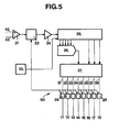
- the receiving electrodes, 19, 20 are connected by wires 42, 43 to the electrical assembly 50 shown in FIG. 5 and the measurement principle of which is illustrated in FIG. 4.
- the electrodes 10 arranged opposite coupling electrodes 6 and 7 are connected to four alternating voltages V1, V2, V x and V x1 .
- the emitting electrodes 10 which are located opposite the central portion of the coupling electrodes 6, respectively 7, are connected to a variable voltage V x , respectively V x1 , while the neighboring electrodes are connected on one side to an alternating voltage of constant amplitude V1 and on the other side to an alternating voltage V2, the voltages V1 and V2 having the same amplitude and frequency, but in phase opposition.
- the variable voltages V x and V x1 have the same frequency as V1 and V2; their amplitude is identical and varies between the amplitude of V1 and V2 passing through 0, they are however of opposite phase.
- FIG. 5 represents the overall diagram of an electronic assembly 50 usable for this purpose.
- the signal received by the wires 42, 43 from the receiving electrodes 19, 20 by capacitive coupling by means of the coupling electrodes 6, 7 is amplified by a differential amplifier 21 and brought at low impedance to a synchronous demodulator 22 controlled by an oscillator 23.
- the signal is then analyzed in a comparator 24 which, in turn, controls the counting and down counting input of a binary counter 25.
- the counting input of the counter 25 is connected, to simplify the representation, also to oscillator 23.
- the output of comparator 24 is also zero and the counter 25 remains stationary.
- the comparator output is switched on and supplies a counting signal to the counter 25. The latter changes its value synchronously with the oscillator 23 and the demodulator 22, until that the signal at the output of the demodulator 22 is equal to zero.
- the low value outputs of the counter 25 control a digital-analog transformer 26 which supplies the modulation voltage for the amplitude variation which occurs linearly as a function of the displacement on the emitting electrodes connected to the variable voltages V x and V x1 .
- This modulation voltage, as well as the high value outputs of the counter, result in a function generator 27 which has 2N outputs (in this case, eight outputs) 31 to 38.
- Each of these outputs 31 to 38 is brought to a modulator 28 connected to the oscillator 23.
- These modulators 28 develop from the pulses given by the oscillator 23 and the modulation voltages delivered to each output 31 to 38 of the generator 27 a wave modulated in the form of an alternating voltage V1, V2, V x or V x1 . These alternating voltages are then routed to the emitting electrodes 10.
- the state of the counter 25 is thus a direct measurement of the position of the emitting electrodes 10 with respect to the coupling electrodes 19, 20, the sum of the alternating currents at the coupling electrodes being zero.
- the high values of the counter 25 constitute a rough measurement of the displacement by counting of whole distances L traversed by the cursor and the low values of the counter 25 represent a fine measurement by linear interpolation. A detailed description of the interpolation method is described in European patent No. 0,053,091.
- V x and V x1 linearly over time, that is to say so as to generate a continuous fictitious displacement, the phase of the crossing points by zero then corresponding to the value of the displacement x.
- the ratio of the T / L center-axes of the coupling and emitting electrodes could be fixed at other values.
- the electronic assembly 50 could be formed differently, for example as described in Swiss Patent No. 643,652.
- the emitting and receiving electrodes could be mounted on the stationary part of the device, while the coupling electrodes would be placed on a sliding rule.
- the device can also be used for angle measurement by placing, for example, the coupling electrodes 6, 7 on the inside periphery of a cylindrical enclosure and the emitting and receiving 10 electrodes 19, 20 on a cylindrical rod arranged so as to rotate inside this enclosure.
Landscapes
- Engineering & Computer Science (AREA)
- Power Engineering (AREA)
- Physics & Mathematics (AREA)
- General Physics & Mathematics (AREA)
- Measurement Of Length, Angles, Or The Like Using Electric Or Magnetic Means (AREA)
Applications Claiming Priority (2)
| Application Number | Priority Date | Filing Date | Title |
|---|---|---|---|
| CH5004/85 | 1985-11-22 | ||
| CH5004/85A CH665714A5 (fr) | 1985-11-22 | 1985-11-22 | Dispositif de mesure capacitif de longueurs et d'angles. |
Publications (2)
| Publication Number | Publication Date |
|---|---|
| EP0227591A1 true EP0227591A1 (de) | 1987-07-01 |
| EP0227591B1 EP0227591B1 (de) | 1990-01-31 |
Family
ID=4286280
Family Applications (1)
| Application Number | Title | Priority Date | Filing Date |
|---|---|---|---|
| EP86810450A Expired - Lifetime EP0227591B1 (de) | 1985-11-22 | 1986-10-10 | Kapazitives Messverfahren für Längen und Winkel |
Country Status (6)
| Country | Link |
|---|---|
| US (1) | US4810951A (de) |
| EP (1) | EP0227591B1 (de) |
| JP (1) | JPS62130301A (de) |
| CN (1) | CN1009028B (de) |
| CH (1) | CH665714A5 (de) |
| DE (1) | DE3668694D1 (de) |
Families Citing this family (13)
| Publication number | Priority date | Publication date | Assignee | Title |
|---|---|---|---|---|
| JPS6421322U (de) * | 1987-08-26 | 1989-02-02 | ||
| JPS6421318U (de) * | 1987-08-26 | 1989-02-02 | ||
| JPS6421316U (de) * | 1987-08-26 | 1989-02-02 | ||
| JPS6421315U (de) * | 1987-08-26 | 1989-02-02 | ||
| US4974332A (en) * | 1988-08-19 | 1990-12-04 | Delta International Machinery Corp. | Measurement system reader element standoff |
| US4958115A (en) * | 1988-11-28 | 1990-09-18 | At&T Bell Laboratories | Capacitively commutated brushless DC servomotors |
| US5174159A (en) * | 1991-06-21 | 1992-12-29 | University Of Utah Research Foundation | Linear displacement and strain measuring apparatus |
| CH689190A5 (fr) * | 1993-10-19 | 1998-11-30 | Hans Ulrich Meyer | Instrument de mesure de longueurs ou d'angles. |
| DE4447295A1 (de) * | 1994-11-10 | 1996-05-15 | Siedle Horst Kg | Verfahren und Vorrichtung zur Bestimmung einer jeweiligen örtlichen Position eines Körpers durch kapazitive Abtastung |
| US5610528A (en) * | 1995-06-28 | 1997-03-11 | International Business Machines Corporation | Capacitive bend sensor |
| US5557584A (en) * | 1995-08-08 | 1996-09-17 | Sonatech, Inc. | Moderate depth underwater surveillance system |
| CN102359754A (zh) * | 2011-08-09 | 2012-02-22 | 张华建 | 差分电容式长度传感器 |
| CN106643455B (zh) * | 2016-12-26 | 2018-11-30 | 清华大学 | 一种电容式旋变位移传感器 |
Citations (6)
| Publication number | Priority date | Publication date | Assignee | Title |
|---|---|---|---|---|
| DE2217183A1 (de) * | 1971-06-23 | 1972-12-28 | Jenoptik Jena Gmbh | Kapazitives Weg- und Winkelmeßsystem |
| US3723866A (en) * | 1970-04-10 | 1973-03-27 | Commissariat Energie Atomique | Capacitive movement measuring device |
| FR2483603A1 (fr) * | 1980-05-27 | 1981-12-04 | Meyer Hans | Dispositif pour la mesure capacitive de deplacements |
| EP0053091A1 (de) * | 1980-11-21 | 1982-06-02 | Hans Ulrich Meyer | Verfahren zum kapazitiven Messen von Längen und Winkeln |
| DE3418566A1 (de) * | 1983-05-18 | 1984-11-22 | Mitutoyo Mfg. Co., Ltd., Tokio/Tokyo | Verschiebungsdetektor |
| DE3340782A1 (de) * | 1983-11-11 | 1985-05-30 | Mauser-Werke Oberndorf Gmbh, 7238 Oberndorf | Kapazitive laengen- und winkelmesseinrichtung |
Family Cites Families (7)
| Publication number | Priority date | Publication date | Assignee | Title |
|---|---|---|---|---|
| US2674729A (en) * | 1950-04-13 | 1954-04-06 | Edward G Martin | Measuring apparatus |
| US3146394A (en) * | 1959-04-29 | 1964-08-25 | Continental Elektro Ind Ag | Apparatus for proportionally converting a rotational angle into a phase angle of an alternating voltage |
| US3219920A (en) * | 1961-04-05 | 1965-11-23 | Whittaker Corp | Transducer employing a guard ring between input and output means to reduce stray capacitances |
| IT1111425B (it) * | 1977-05-18 | 1986-01-13 | Conte Alberto | Trasduttore assoluto di precisione per misure di posizioni lineari od angolari |
| JPS568508A (en) * | 1979-07-02 | 1981-01-28 | Nippon Soken Inc | Rotation detector |
| US4429307A (en) * | 1982-01-29 | 1984-01-31 | Dataproducts Corporation | Capacitive transducer with continuous sinusoidal output |
| US4522517A (en) * | 1983-11-10 | 1985-06-11 | Wade Kenneth B | Encoder system for dot matrix line printer |
-
1985
- 1985-11-22 CH CH5004/85A patent/CH665714A5/fr not_active IP Right Cessation
-
1986
- 1986-10-10 EP EP86810450A patent/EP0227591B1/de not_active Expired - Lifetime
- 1986-10-10 DE DE8686810450T patent/DE3668694D1/de not_active Expired - Lifetime
- 1986-11-21 CN CN86107942.6A patent/CN1009028B/zh not_active Expired
- 1986-11-21 US US06/933,468 patent/US4810951A/en not_active Expired - Fee Related
- 1986-11-21 JP JP61278495A patent/JPS62130301A/ja active Pending
Patent Citations (6)
| Publication number | Priority date | Publication date | Assignee | Title |
|---|---|---|---|---|
| US3723866A (en) * | 1970-04-10 | 1973-03-27 | Commissariat Energie Atomique | Capacitive movement measuring device |
| DE2217183A1 (de) * | 1971-06-23 | 1972-12-28 | Jenoptik Jena Gmbh | Kapazitives Weg- und Winkelmeßsystem |
| FR2483603A1 (fr) * | 1980-05-27 | 1981-12-04 | Meyer Hans | Dispositif pour la mesure capacitive de deplacements |
| EP0053091A1 (de) * | 1980-11-21 | 1982-06-02 | Hans Ulrich Meyer | Verfahren zum kapazitiven Messen von Längen und Winkeln |
| DE3418566A1 (de) * | 1983-05-18 | 1984-11-22 | Mitutoyo Mfg. Co., Ltd., Tokio/Tokyo | Verschiebungsdetektor |
| DE3340782A1 (de) * | 1983-11-11 | 1985-05-30 | Mauser-Werke Oberndorf Gmbh, 7238 Oberndorf | Kapazitive laengen- und winkelmesseinrichtung |
Non-Patent Citations (1)
| Title |
|---|
| IBM TECHNICAL DISCLOSURE BULLETIN, vol. 21, no. 1, juin 1978, pages 242-243, New York, US; D.R. DOBSON et al.: "Position encoder" * |
Also Published As
| Publication number | Publication date |
|---|---|
| JPS62130301A (ja) | 1987-06-12 |
| DE3668694D1 (de) | 1990-03-08 |
| CN86107942A (zh) | 1987-07-15 |
| EP0227591B1 (de) | 1990-01-31 |
| CH665714A5 (fr) | 1988-05-31 |
| CN1009028B (zh) | 1990-08-01 |
| US4810951A (en) | 1989-03-07 |
Similar Documents
| Publication | Publication Date | Title |
|---|---|---|
| EP0227591B1 (de) | Kapazitives Messverfahren für Längen und Winkel | |
| EP0053091B1 (de) | Verfahren zum kapazitiven Messen von Längen und Winkeln | |
| EP0785415B1 (de) | Induktiver Weggeber | |
| CA1174871A (fr) | Thermometre a quartz | |
| FR3033647B1 (fr) | Capteur de courant pour mesurer un courant alternatif | |
| EP0453824B1 (de) | Sensor zur Messung der relativen transversalen Verschiebung eines leitenden Stückes in länglicher Form | |
| EP0157663B1 (de) | Beschleunigungsaufnehmer mit flachem, pendelartigem Aufbau | |
| EP0225229B1 (de) | Elektromagnetischer Durchflussmesser mit gepulstem Magnetfeld | |
| EP0871012A1 (de) | Durch Mikromaterialbearbeitung hergestellter Sensor, insbesondere Wegsensor | |
| FR2682760A1 (fr) | Capteurs de deplacements lineaires ou angulaires sans contact. | |
| EP0648998A2 (de) | Instrument zum Messen der Längen oder Winkel | |
| FR2527413A1 (fr) | Accelerateur lineaire de particules chargees comportant des tubes de glissement | |
| CH670306A5 (de) | ||
| EP0877228A1 (de) | Magnetoresistiver Sensor für Dimensionsbestimmung | |
| FR2476849A1 (fr) | Appareil pour la mesure d'un champ electrique | |
| EP1071927B1 (de) | Inkrementaler positionsgeber | |
| EP0441074B1 (de) | Induktiver Sensor und Vorrichtung zum messen der Verschiebung eines mobilen Gegenstandes | |
| EP1052519B1 (de) | Magnetischer F?hler hergestellt auf einem halbleitenden Substrat | |
| EP0136238B1 (de) | Vorrichtung zur Messung der Nähe einer metallisch leitenden Oberfläche | |
| CH632839A5 (fr) | Dispositif de detection d'angle de rotation. | |
| FR2537787A1 (fr) | Dispositif d'antenne pour radiogoniometre | |
| FR2784179A1 (fr) | Chaine de mesure capacitive | |
| FR2466747A1 (fr) | Procede et installation de controle du diametre d'un fil ou cable | |
| EP0671013B1 (de) | Anordnung zur magnetischer messung für schiffe | |
| WO1997018438A1 (fr) | Procede et dispositif pour mesurer un ecart axial dans un systeme d'alignement a fil tendu |
Legal Events
| Date | Code | Title | Description |
|---|---|---|---|
| PUAI | Public reference made under article 153(3) epc to a published international application that has entered the european phase |
Free format text: ORIGINAL CODE: 0009012 |
|
| AK | Designated contracting states |
Kind code of ref document: A1 Designated state(s): DE FR GB |
|
| 17P | Request for examination filed |
Effective date: 19870926 |
|
| 17Q | First examination report despatched |
Effective date: 19890131 |
|
| GRAA | (expected) grant |
Free format text: ORIGINAL CODE: 0009210 |
|
| AK | Designated contracting states |
Kind code of ref document: B1 Designated state(s): DE FR GB |
|
| REF | Corresponds to: |
Ref document number: 3668694 Country of ref document: DE Date of ref document: 19900308 |
|
| GBT | Gb: translation of ep patent filed (gb section 77(6)(a)/1977) | ||
| PLBE | No opposition filed within time limit |
Free format text: ORIGINAL CODE: 0009261 |
|
| STAA | Information on the status of an ep patent application or granted ep patent |
Free format text: STATUS: NO OPPOSITION FILED WITHIN TIME LIMIT |
|
| 26N | No opposition filed | ||
| PGFP | Annual fee paid to national office [announced via postgrant information from national office to epo] |
Ref country code: FR Payment date: 19920918 Year of fee payment: 7 |
|
| PGFP | Annual fee paid to national office [announced via postgrant information from national office to epo] |
Ref country code: GB Payment date: 19921007 Year of fee payment: 7 |
|
| PGFP | Annual fee paid to national office [announced via postgrant information from national office to epo] |
Ref country code: DE Payment date: 19921119 Year of fee payment: 7 |
|
| PG25 | Lapsed in a contracting state [announced via postgrant information from national office to epo] |
Ref country code: GB Effective date: 19931010 |
|
| GBPC | Gb: european patent ceased through non-payment of renewal fee |
Effective date: 19931010 |
|
| PG25 | Lapsed in a contracting state [announced via postgrant information from national office to epo] |
Ref country code: FR Effective date: 19940630 |
|
| PG25 | Lapsed in a contracting state [announced via postgrant information from national office to epo] |
Ref country code: DE Effective date: 19940701 |
|
| REG | Reference to a national code |
Ref country code: FR Ref legal event code: ST |