EP0157663B1 - Beschleunigungsaufnehmer mit flachem, pendelartigem Aufbau - Google Patents
Beschleunigungsaufnehmer mit flachem, pendelartigem Aufbau Download PDFInfo
- Publication number
- EP0157663B1 EP0157663B1 EP85400329A EP85400329A EP0157663B1 EP 0157663 B1 EP0157663 B1 EP 0157663B1 EP 85400329 A EP85400329 A EP 85400329A EP 85400329 A EP85400329 A EP 85400329A EP 0157663 B1 EP0157663 B1 EP 0157663B1
- Authority
- EP
- European Patent Office
- Prior art keywords
- test body
- sensor
- metallized
- fixed part
- edge
- Prior art date
- Legal status (The legal status is an assumption and is not a legal conclusion. Google has not performed a legal analysis and makes no representation as to the accuracy of the status listed.)
- Expired
Links
- 230000001133 acceleration Effects 0.000 title claims description 8
- 238000012360 testing method Methods 0.000 claims description 107
- 239000003990 capacitor Substances 0.000 claims description 27
- 238000001465 metallisation Methods 0.000 claims description 11
- 238000001514 detection method Methods 0.000 claims description 7
- 230000000630 rising effect Effects 0.000 claims description 7
- 230000003321 amplification Effects 0.000 claims description 5
- 238000005459 micromachining Methods 0.000 claims description 5
- 238000003199 nucleic acid amplification method Methods 0.000 claims description 5
- 230000005484 gravity Effects 0.000 claims description 4
- 229910052782 aluminium Inorganic materials 0.000 claims description 2
- XAGFODPZIPBFFR-UHFFFAOYSA-N aluminium Chemical compound [Al] XAGFODPZIPBFFR-UHFFFAOYSA-N 0.000 claims description 2
- 230000004907 flux Effects 0.000 claims description 2
- 229910052709 silver Inorganic materials 0.000 claims description 2
- 239000004332 silver Substances 0.000 claims description 2
- 238000013519 translation Methods 0.000 claims description 2
- 238000007373 indentation Methods 0.000 claims 3
- 239000004411 aluminium Substances 0.000 claims 1
- 238000006073 displacement reaction Methods 0.000 description 16
- 230000002787 reinforcement Effects 0.000 description 7
- 239000004020 conductor Substances 0.000 description 6
- 238000005259 measurement Methods 0.000 description 5
- 230000006698 induction Effects 0.000 description 4
- 230000035945 sensitivity Effects 0.000 description 4
- XUIMIQQOPSSXEZ-UHFFFAOYSA-N Silicon Chemical compound [Si] XUIMIQQOPSSXEZ-UHFFFAOYSA-N 0.000 description 3
- 239000010453 quartz Substances 0.000 description 3
- VYPSYNLAJGMNEJ-UHFFFAOYSA-N silicon dioxide Inorganic materials O=[Si]=O VYPSYNLAJGMNEJ-UHFFFAOYSA-N 0.000 description 3
- 229910001020 Au alloy Inorganic materials 0.000 description 2
- 239000003353 gold alloy Substances 0.000 description 2
- 229910052751 metal Inorganic materials 0.000 description 2
- 239000002184 metal Substances 0.000 description 2
- 238000000034 method Methods 0.000 description 2
- 229910052710 silicon Inorganic materials 0.000 description 2
- 239000010703 silicon Substances 0.000 description 2
- 239000000758 substrate Substances 0.000 description 2
- 208000031968 Cadaver Diseases 0.000 description 1
- BQCADISMDOOEFD-UHFFFAOYSA-N Silver Chemical compound [Ag] BQCADISMDOOEFD-UHFFFAOYSA-N 0.000 description 1
- 238000005520 cutting process Methods 0.000 description 1
- 238000013461 design Methods 0.000 description 1
- 238000010586 diagram Methods 0.000 description 1
- 230000000694 effects Effects 0.000 description 1
- PCHJSUWPFVWCPO-UHFFFAOYSA-N gold Chemical compound [Au] PCHJSUWPFVWCPO-UHFFFAOYSA-N 0.000 description 1
- 239000010931 gold Substances 0.000 description 1
- 229910052737 gold Inorganic materials 0.000 description 1
- 238000003754 machining Methods 0.000 description 1
- 238000004519 manufacturing process Methods 0.000 description 1
- 239000000463 material Substances 0.000 description 1
- 150000002739 metals Chemical class 0.000 description 1
- 239000000126 substance Substances 0.000 description 1
- 238000004804 winding Methods 0.000 description 1
Images


Classifications
-
- G—PHYSICS
- G01—MEASURING; TESTING
- G01P—MEASURING LINEAR OR ANGULAR SPEED, ACCELERATION, DECELERATION, OR SHOCK; INDICATING PRESENCE, ABSENCE, OR DIRECTION, OF MOVEMENT
- G01P15/00—Measuring acceleration; Measuring deceleration; Measuring shock, i.e. sudden change of acceleration
- G01P15/02—Measuring acceleration; Measuring deceleration; Measuring shock, i.e. sudden change of acceleration by making use of inertia forces using solid seismic masses
- G01P15/08—Measuring acceleration; Measuring deceleration; Measuring shock, i.e. sudden change of acceleration by making use of inertia forces using solid seismic masses with conversion into electric or magnetic values
- G01P15/125—Measuring acceleration; Measuring deceleration; Measuring shock, i.e. sudden change of acceleration by making use of inertia forces using solid seismic masses with conversion into electric or magnetic values by capacitive pick-up
-
- G—PHYSICS
- G01—MEASURING; TESTING
- G01P—MEASURING LINEAR OR ANGULAR SPEED, ACCELERATION, DECELERATION, OR SHOCK; INDICATING PRESENCE, ABSENCE, OR DIRECTION, OF MOVEMENT
- G01P15/00—Measuring acceleration; Measuring deceleration; Measuring shock, i.e. sudden change of acceleration
- G01P15/02—Measuring acceleration; Measuring deceleration; Measuring shock, i.e. sudden change of acceleration by making use of inertia forces using solid seismic masses
-
- G—PHYSICS
- G01—MEASURING; TESTING
- G01P—MEASURING LINEAR OR ANGULAR SPEED, ACCELERATION, DECELERATION, OR SHOCK; INDICATING PRESENCE, ABSENCE, OR DIRECTION, OF MOVEMENT
- G01P15/00—Measuring acceleration; Measuring deceleration; Measuring shock, i.e. sudden change of acceleration
- G01P15/02—Measuring acceleration; Measuring deceleration; Measuring shock, i.e. sudden change of acceleration by making use of inertia forces using solid seismic masses
- G01P15/08—Measuring acceleration; Measuring deceleration; Measuring shock, i.e. sudden change of acceleration by making use of inertia forces using solid seismic masses with conversion into electric or magnetic values
- G01P15/0802—Details
-
- G—PHYSICS
- G01—MEASURING; TESTING
- G01P—MEASURING LINEAR OR ANGULAR SPEED, ACCELERATION, DECELERATION, OR SHOCK; INDICATING PRESENCE, ABSENCE, OR DIRECTION, OF MOVEMENT
- G01P15/00—Measuring acceleration; Measuring deceleration; Measuring shock, i.e. sudden change of acceleration
- G01P15/02—Measuring acceleration; Measuring deceleration; Measuring shock, i.e. sudden change of acceleration by making use of inertia forces using solid seismic masses
- G01P15/08—Measuring acceleration; Measuring deceleration; Measuring shock, i.e. sudden change of acceleration by making use of inertia forces using solid seismic masses with conversion into electric or magnetic values
- G01P15/13—Measuring acceleration; Measuring deceleration; Measuring shock, i.e. sudden change of acceleration by making use of inertia forces using solid seismic masses with conversion into electric or magnetic values by measuring the force required to restore a proofmass subjected to inertial forces to a null position
- G01P15/132—Measuring acceleration; Measuring deceleration; Measuring shock, i.e. sudden change of acceleration by making use of inertia forces using solid seismic masses with conversion into electric or magnetic values by measuring the force required to restore a proofmass subjected to inertial forces to a null position with electromagnetic counterbalancing means
-
- G—PHYSICS
- G01—MEASURING; TESTING
- G01P—MEASURING LINEAR OR ANGULAR SPEED, ACCELERATION, DECELERATION, OR SHOCK; INDICATING PRESENCE, ABSENCE, OR DIRECTION, OF MOVEMENT
- G01P15/00—Measuring acceleration; Measuring deceleration; Measuring shock, i.e. sudden change of acceleration
- G01P15/02—Measuring acceleration; Measuring deceleration; Measuring shock, i.e. sudden change of acceleration by making use of inertia forces using solid seismic masses
- G01P15/08—Measuring acceleration; Measuring deceleration; Measuring shock, i.e. sudden change of acceleration by making use of inertia forces using solid seismic masses with conversion into electric or magnetic values
- G01P2015/0805—Measuring acceleration; Measuring deceleration; Measuring shock, i.e. sudden change of acceleration by making use of inertia forces using solid seismic masses with conversion into electric or magnetic values being provided with a particular type of spring-mass-system for defining the displacement of a seismic mass due to an external acceleration
- G01P2015/0822—Measuring acceleration; Measuring deceleration; Measuring shock, i.e. sudden change of acceleration by making use of inertia forces using solid seismic masses with conversion into electric or magnetic values being provided with a particular type of spring-mass-system for defining the displacement of a seismic mass due to an external acceleration for defining out-of-plane movement of the mass
- G01P2015/0825—Measuring acceleration; Measuring deceleration; Measuring shock, i.e. sudden change of acceleration by making use of inertia forces using solid seismic masses with conversion into electric or magnetic values being provided with a particular type of spring-mass-system for defining the displacement of a seismic mass due to an external acceleration for defining out-of-plane movement of the mass for one single degree of freedom of movement of the mass
- G01P2015/0828—Measuring acceleration; Measuring deceleration; Measuring shock, i.e. sudden change of acceleration by making use of inertia forces using solid seismic masses with conversion into electric or magnetic values being provided with a particular type of spring-mass-system for defining the displacement of a seismic mass due to an external acceleration for defining out-of-plane movement of the mass for one single degree of freedom of movement of the mass the mass being of the paddle type being suspended at one of its longitudinal ends
Definitions
- the present invention relates to an accelerometric sensor of the type comprising a plane pendular structure in which the sensitive axis is located in the plane of the structure, in contrast to accelerometric sensors such as that described in patent GB-A-2 101 336 in which the sensitive axis is perpendicular to the plane of the test body.
- the pendulum structure can be produced by micro-machining of a crystalline plate for example in silicon or quartz and comprises a flat test body suspended by two parallel flexible blades in the plane of said test body.
- a first object of the invention is therefore to design a pendulum structure of the type of that previously mentioned, the geometric shapes of which make it possible to reduce the transverse stresses exerted on the flexible blades by the test body when the latter is subjected to transverse efforts (transverse accelerations).
- the invention provides a pendulum structure of the type comprising a flat fixed part and a flat test body suspended on said fixed part by two flexible parallel blades in the plane of said test body, so as to be able to move in translation along an axis along which the acceleration is measured, said test body extending at least partially in the space between the two flexible blades.
- this sensor is more particularly characterized in that the above fixed part, the above test body and the above flexible blades are produced in a single piece obtained by micromachining of a crystalline blade, and in that, consequently, said fixed part, said test body and said flexible blades extend in the same plane
- the determination of the accelerations necessarily involves the detection of the displacements of the test body.
- the object of the invention is therefore also to produce capacitive detectors intended for measuring the translational displacements of the test body, specifically designed for the pendulum structure previously described.
- these capacitive displacement detectors comprise at least a first capacitor armature carried by at least one region of the edge of the test body substantially perpendicular to the sensitive axis of the sensor, and a second capacitor armature carried by at least one region of the edge of the fixed part of the pendulum element, parallel to the first armature and slightly spaced from the latter.
- These two capacitor plates can advantageously be obtained by metallization of said zones of the edge of the test body and of the fixed part of the pendulum structure.
- the above capacitive detectors involve at least one capacitor armature, consisting of at least one strip of electrically conductive material, carried by one face of the test body and at least one second. strip of electrically conductive material extending parallel to the first strip and slightly spaced therefrom, this second strip being carried by a frame secured to the fixed part of the pendular structure.
- the electrical connections between the capacitor plates carried by the test body and the electronic circuit carried by the fixed part of the pendulum structure are advantageously produced by metallization of the thin faces of the flexible blades ( parallel to the plane of the structure).
- the senor may also include a return motor counterbalancing the external action exerted on the test body.
- this motor uses, in a conventional manner, the Laplace force obtained by the action of a magnetic induction on a current flowing in a coil printed on the periphery of at least one of the two faces of the test body.
- This coil can be produced by known methods such as metallic deposits, the chemical attack of a uniform deposit, etc.
- the connections with the outside are effected by means of conductive pads, possibly Lely obtained by metallization, carried by the thin faces of the flexible blades, which are not used for the electrical connection of the capacitor plates.
- the test body may comprise at least one metallized passage between its two faces allowing an arrangement of these electrical connections on one and / or the other face of said test body.
- the magnetic circuit for producing the magnetic induction on the coil then consists of a permanent magnet, magnetized transversely and provided with two pole pieces which extend parallel to a face of the test body and at a short distance from it. this. This magnetic circuit is looped back by an armature which extends parallel to the other face of the body.
- the above coils comprise two opposite rectilinear zones, perpendicular to the sensitive axis of the sensor and traversed by a current flowing in the opposite direction.
- the abovementioned pole pieces are arranged so as to cover these two rectilinear zones respectively, so that the forces generated at these two rectilinear zones on the test body by the circulation of current in the coil, work in the direction of the sensitive axis and in the same direction.
- the flexible blades 4, 5 have, in the plane of the structure, a width as small as possible. Their thickness is that of the crystalline plate. Consequently, these blades 4, 5 have a very low stiffness in the plane of the structure, while they have a relatively large stiffness perpendicular to this plane.
- the sensitive axis zx of this structure is therefore located in the plane of the structure and is perpendicular to the flexible blades 4, 5.
- each of the flexible blades 4, 5 will comprise two parallel sections, namely an inner section 7 oriented towards the test body 6 and an outer section 8 oriented towards the outside.
- the test body 6 comprises two lateral sections 9, 10 extending parallel to the internal sections of the flexible blades 4, 5. an internal longitudinal section 11 connecting the two lateral sections 9, 10 parallel to a corresponding internal section 12 of the fixed part 1 of the structure, and an outer longitudinal section 13 situated slightly beyond the ends of the flexible blades 4, 5.
- the connection of the flexible blades 4, 5 on the test body 6 is effected by the intermediate of two lateral recesses 14, 14 ′ provided on the test body 6 for determining the spacing between the flexible blades 4, 5 and the lateral edges 9, 10 of the test body 6.
- the pendulum structure can be obtained by making a U-shaped recess in the crystalline plate forming the inner edges 7 of the flexible blades 4, 5, the two lateral edges 9. 10 and the longitudinal edge inner 11 of the test body 6 as well as the inner edge 12 of the fixed part 1 of the structure.
- outer edges 8 of the flexible blades 4, 5 and the outer longitudinal edge 13 of the test body 6 can be obtained by cutting in the shape of an inverted U.
- test body 6 further comprises a rectangular recess 15 used to lighten the structure.
- This pendular structure has the advantage of bringing the center of gravity G as close as possible to the test body of the feet 2, 3 of the flexible blades 4, 5.
- the invention is not limited to the shape of the pendulum structure shown on Figure 1. This can in particular be adapted to allow the mounting of capacitive detectors.
- these detectors necessarily involve at least two capacitor plates movable relative to each other, one being carried by the test body 6 and the other being integral with the fixed part. 1 of the pendulum structure, these two frames being arranged such that a displacement of the test body 6 along its axis of measurement ⁇ x. causes a corresponding variation in the capacity, the measurement of this variation in capacity making it possible to determine the amplitude of the displacement of the test body 6 and, consequently, of the component of the acceleration along the measurement axis ⁇ x.
- detectors with frontal displacements such as those represented in FIGS. 2 to 5 which involve at least two parallel reinforcements, perpendicular to the sensitive axis rx of the pendular structure and whose spacing and, consequently, the capacity vary according to displacements of the test body 6, and
- the lateral displacement detectors such as those represented in FIGS. 6 and 7 which involve at least two armatures parallel to the measurement axis Tx in this case, the spacing between the two armatures is constant and the displacement of the body test 6 causes a shift of one of the reinforcements with respect to the other and, consequently, a variation in capacity.
- the lateral sides of the test body comprise two extensions 16, 17 extending outward, beyond the points of junction of the flexible blades 4, 5 with the body of test 6.
- These two lateral extensions 16, 17 each include a straight edge 18, 19 perpendicular to the sensitive axis T x of the structure and extending substantially in the plane of the corresponding flexible strip.
- These sections 18, 19 are metallized and form two capacitor plates.
- the fixed part 1 comprises two wings 20, 21 having, in parallel to and in line with the metallized sections 18, 19, two respective metallized sections 22, 23 forming two capacitor plates associated with the plates formed by the sections 18 , 19.
- the capacitive detector equipping the pendulum structure shown in FIG. 3 involves two reinforcements formed by the metallization of the two internal lateral sections 9, 10 of the test body 6, these two reinforcements cooperating with two respective reinforcements formed by the metallization of parallel sections corresponding 25, 26 of two wings 27, 28 of the fixed part 1 of the pendulum structure which extend respectively into the space between the two flexible blades 4, 5 and the inner lateral sections 9, 10 of the test body 6.
- the test body 6 comprises two lateral extensions 29, 30 extending outside, beyond the junction points of the flexible blades 4, 5 and of the test body 6, and coming back to the anchor points 2, 3 of said flexible blades 4, 5 on the fixed part 1 of the pendulum structure.
- these two lateral extensions comprise external lateral sections 32, 33 perpendicular to the sensitive axis ⁇ x of the pendular structure.
- These sections 32, 33 are metallized to form capacitor plates which cooperate with corresponding parallel metallized sections 34, 35 of two external lateral wings 36, 37 of the fixed part 1 of the pendular structure.
- the inner longitudinal section 11 of the test body 6 and the corresponding inner section 12 of the fixed part 1 of the pendulum structure have slot shapes, the slots of one of these sections s 'engaging in the intervals between the slots of the other bracket.
- FIG. 5 shows an embodiment of the connections of the armatures of these capacitors.
- the metallic falling edges of the lower longitudinal section 11 of the test body 6 are connected to an AC voltage source + E by conductors 38, while the metallized rising edges of this section are connected by conductors 39 to an alternating voltage source - E, in phase opposition with the voltage source + E.
- the collection of the difference voltage is carried out on the metallized rising and falling edges of the inner edge 12 of the fixed part of the pendulum structure, which are connected in parallel by means of a conductor 40.
- the advantage of the structure described above consists first of all in that it makes it possible to place the center of gravity G of the test body exactly in the middle of the length of the flexible blades 4, 5 (which allows, under the influence of a transverse acceleration T y, a displacement of the test body 6 parallel to itself) or even even closer to the feet 2, 3 of the flexible blades 4, 5, which allows a reduction in the stresses exerted on said blades 4, 5, when the test body 6 is subjected to a transverse acceleration T ' j.
- This solution also allows a significant increase in the surface area of the detectors and. as a result, increased sensitivity. It also allows a reduction in the distances between the detection zones and the amplification circuit of the deviation signal, and, consequently, a reduction in the risks of disturbance.
- the longitudinal edge of the test body, opposite the inner longitudinal edge 11, and a corresponding edge of the fixed part can also have slot shapes which interpenetrate each other.
- the rising and falling edges of these slots can then be metallized to form capacitor plates.
- the capacitive detectors equipping the pendulum structure according to the invention can be of the type with lateral displacement.
- FIG. 6 provides an exemplary embodiment of such a detector in a pendulum structure of the type of that shown in FIG. 1, but in which the test body 6 comprises two central recesses 41, 42 separated by a central strip 43 substantially parallel to the flexible blades 4, 5.
- This central strip 43 carries on one side two parallel conductive pads 44, 45 slightly distant from each other and which can be produced by flat metallization. These two conductive pads 44, 45 which constitute two capacitor plates, cooperate with a conductive pad 46, parallel to the plane of the test body 6 and spaced from it by a distance for example of the order of a few hundredths of millimeters. This conductive pad 46 is carried by a frame 47 secured to the fixed part 1 of the pendulum structure.
- the conductive pad 46 is centered in the median plane of symmetry of the two conductive pads 44, 45, so that during a displacement of the test body 6 in its plane, the capacity of the plane capacitor formed by the pad conductor 46 and one of the two conductive pads 44, 45 of the test body will increase, while the capacity of the flat capacitor formed by the conductive pad 46 and the other conductive pad 44, 45 of the test body 6 will decrease.
- tracks 44 and 45 are respectively connected to two alternating voltage sources in phase opposition + E and - E, while track 46 is connected to an amplification and detection circuit of the deviation signal.
- the inner longitudinal section 12 of the fixed part 1 of the pendulum structure is located below the anchor points 2, 3 or feet of the flexible blades 4, 5.
- ie body 6 comprises, in the vicinity of this section 12, an area on which a plurality of pairs of conductive pads of the type of pads 44, 45 used in the pendulum structure shown in FIG. 6 is made. These pairs of conductive pads are connected in parallel and form two crenellated circuits 50, 51 whose slots are intertwined. One of these circuits 50 is connected to an AC voltage source + E, while the other circuit 51 is connected to an AC voltage source - E in phase opposition with the source + E.
- These pairs of conductive pads each cooperate with a corresponding conductive pad carried by a frame 47 in a manner similar to that described in connection with FIG. 6.
- These conductive pads which are in the form of a comb 53 are connected to a amplification and detection circuit of the deviation signal.
- Such an arrangement makes it possible to increase the gain of the sensor and / or to decrease the height of the pendulum structure for a given gain (better use of the surface of the substrate).
- FIG. 8 illustrates an embodiment of the connections of a sensor of the type represented in FIG. 7, the test body of which is equipped with two coils (one per side 55, 56).
- the crenellated circuit 50 of the capacitive detector is connected to a connection pad 57 located on the fixed part 1 of the pendulum structure by means of an electrical connection provided on the front face of the pendulum structure and comprising a conductive strip 58 extending flat on the lateral edge of the test body 6 or even optionally on the edge 10 thereof, this conductive strip being connected to one of the thin metallized faces of the flexible blade 5, itself connected, at foot 3, to the connection pad 57.
- the crenellated circuit 51 of the capacitive detector is connected to a connection pad 60 provided on the rear face 56 of the fixed part of the pendulum structure by means of an electrical connection comprising a conductive strip 61 extending on the lateral border of the rear face 56 of the test body 6 or even on the edge 9 thereof, this conductive strip being connected to one thin metallic faces of the flexible blade 4, itself connected, at foot 2, to the connection pad 60.
- the two faces of the test body 6 each comprise a return motor coil 62, 63 produced for example by flat metallization which extend at the periphery of the test body 6 around the central recess 15 .
- connection pad 64 provided on the fixed part 1 of the pendulum structure by an electrical connection formed for example by metallization of the other thin face of the flexible blade 4.
- the interior end of the coil 62 is connected to the interior end of the coil 63 (located on the other face 56), by a current passage 65 formed on the edge bordering the recess 15.
- connection pad 66 provided on the fixed part 1 of the pendulum structure, by an electrical connection formed for example by metallization of the other thin face of the flexible blade 5.
- connection pads 57, 60, 64, 66 correspond to the input / output terminals of the sensor, the terminals 64, 66 serving for the return motor and the terminals 57, 60 when the capacitive detector is energized. .
- test body could include only one coil.
- current flows from one face to the other of the test body could be made, either by the edge, and / or by metallized holes.
- the previously described accelerometric sensors require a test body return motor intended to counterbalance the external action.
- This return motor can use, in a conventional manner, the Laplace force obtained by the action of a magnetic induction on a current flowing in at least one coil printed on one of the two faces of the test body.
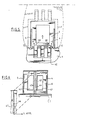
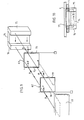
- FIGS. 9 and 10 An embodiment of such a return motor is shown diagrammatically in FIGS. 9 and 10.
- This return motor involves two coils 62, 63 respectively mounted on the two faces of the test body 6 as in the case of FIG. 8.
- Each of these coils 62, 63 has a rectangular shape and includes two lateral zones 70, 71, 72, 73, in which the turns are rectilinear and traversed by a current flowing in the opposite direction.
- the magnetic circuit consists of a permanent magnet 74, magnetized transversely, of two pole pieces 75, 76 associated with the magnet 74 and arranged on one side of the test body 6 in line with the two zones 70, 72 and 71 , 73 of the coils 62, 63, and of a reinforcement for looping the flow 77 located parallel to the other face of the test body.
- the winding direction of the turns of the two coils 62, 63 is provided so that the Laplace forces generated by the magnetic induction B on the zones 70, 72 and 71, 73 of the coils 62. 63 are oriented in the same direction (in the plane of the test body) and adding to each other.
- the metal deposited on the pendulum structure to form the electrical circuits can consist of gold or a gold alloy such as a chrome-gold alloy for example.
- these circuits are preferably made of silver or aluminum, metals which in particular have better electrical conductivity and a lower specific mass.
- the previously described accelerometric sensor can be housed in a housing comprising a base and a cover.
- the assembly constituted by the permanent magnet and the pole pieces can be secured to the base, while the reinforcement for looping the flux can be carried by the housing.
- Such an arrangement considerably simplifies the assembly of the sensor.
Landscapes
- Physics & Mathematics (AREA)
- General Physics & Mathematics (AREA)
- Electromagnetism (AREA)
- Measurement Of Length, Angles, Or The Like Using Electric Or Magnetic Means (AREA)
- Pressure Sensors (AREA)
- Measurement Of Mechanical Vibrations Or Ultrasonic Waves (AREA)
Claims (22)
Applications Claiming Priority (2)
| Application Number | Priority Date | Filing Date | Title |
|---|---|---|---|
| FR8403441A FR2560997B1 (fr) | 1984-03-06 | 1984-03-06 | Capteur accelerometrique a structure pendulaire plane |
| FR8403441 | 1984-03-06 |
Publications (2)
| Publication Number | Publication Date |
|---|---|
| EP0157663A1 EP0157663A1 (de) | 1985-10-09 |
| EP0157663B1 true EP0157663B1 (de) | 1988-03-23 |
Family
ID=9301743
Family Applications (1)
| Application Number | Title | Priority Date | Filing Date |
|---|---|---|---|
| EP85400329A Expired EP0157663B1 (de) | 1984-03-06 | 1985-02-22 | Beschleunigungsaufnehmer mit flachem, pendelartigem Aufbau |
Country Status (5)
| Country | Link |
|---|---|
| US (1) | US4663972A (de) |
| EP (1) | EP0157663B1 (de) |
| JP (1) | JPH065231B2 (de) |
| DE (1) | DE3561977D1 (de) |
| FR (1) | FR2560997B1 (de) |
Families Citing this family (26)
| Publication number | Priority date | Publication date | Assignee | Title |
|---|---|---|---|---|
| JPS63149569A (ja) * | 1986-12-12 | 1988-06-22 | Canon Inc | 加速度計 |
| DE3885568T2 (de) * | 1987-10-02 | 1994-03-17 | Sextant Avionique | Flacher Pendelbeschleunigungsaufnehmer. |
| ATE84151T1 (de) * | 1988-10-11 | 1993-01-15 | Richard A Hanson | Pendelanordnung. |
| DE4022464C2 (de) * | 1990-07-14 | 2000-12-28 | Bosch Gmbh Robert | Beschleunigungssensor |
| EP0543901B1 (de) * | 1990-08-17 | 1995-10-04 | Analog Devices, Inc. | Monolithischer beschleunigungsmesser |
| US5314572A (en) * | 1990-08-17 | 1994-05-24 | Analog Devices, Inc. | Method for fabricating microstructures |
| US5326726A (en) * | 1990-08-17 | 1994-07-05 | Analog Devices, Inc. | Method for fabricating monolithic chip containing integrated circuitry and suspended microstructure |
| US5111694A (en) * | 1990-08-17 | 1992-05-12 | Sundstrand Corporation | Accelerometer with rebalance coil stress isolation |
| US5417111A (en) | 1990-08-17 | 1995-05-23 | Analog Devices, Inc. | Monolithic chip containing integrated circuitry and suspended microstructure |
| US5620931A (en) * | 1990-08-17 | 1997-04-15 | Analog Devices, Inc. | Methods for fabricating monolithic device containing circuitry and suspended microstructure |
| FR2667157B1 (fr) * | 1990-09-25 | 1994-06-10 | Sextant Avionique | Micro-accelerometre a resonateurs et procede de fabrication. |
| US5421213A (en) | 1990-10-12 | 1995-06-06 | Okada; Kazuhiro | Multi-dimensional force detector |
| US6314823B1 (en) | 1991-09-20 | 2001-11-13 | Kazuhiro Okada | Force detector and acceleration detector and method of manufacturing the same |
| DE4126107C2 (de) * | 1991-08-07 | 1993-12-16 | Bosch Gmbh Robert | Beschleunigungssensor und Verfahren zur Herstellung |
| US6199874B1 (en) | 1993-05-26 | 2001-03-13 | Cornell Research Foundation Inc. | Microelectromechanical accelerometer for automotive applications |
| US6149190A (en) * | 1993-05-26 | 2000-11-21 | Kionix, Inc. | Micromechanical accelerometer for automotive applications |
| DE4341271B4 (de) * | 1993-12-03 | 2005-11-03 | Robert Bosch Gmbh | Beschleunigungssensor aus kristallinem Material und Verfahren zur Herstellung dieses Beschleunigungssensors |
| DE4400127C2 (de) * | 1994-01-05 | 2003-08-14 | Bosch Gmbh Robert | Kapazitiver Beschleunigungssensor und Verfahren zu seiner Herstellung |
| US5565625A (en) * | 1994-12-01 | 1996-10-15 | Analog Devices, Inc. | Sensor with separate actuator and sense fingers |
| FR2734641B1 (fr) * | 1995-05-24 | 1997-08-14 | Sextant Avionique | Accelerometre electromagnetique |
| JPH1114658A (ja) * | 1997-06-25 | 1999-01-22 | Mitsubishi Electric Corp | 静電容量式加速度センサ |
| GB0000619D0 (en) * | 2000-01-13 | 2000-03-01 | British Aerospace | Accelerometer |
| KR20050107470A (ko) * | 2003-02-28 | 2005-11-11 | 배 시스템즈 피엘시 | 가속도계 |
| FR2910635B1 (fr) * | 2006-12-20 | 2009-03-06 | Thales Sa | Lame de guidage de masse d'epreuve et systeme electromecanique micro-usine comportant une telle lame |
| US10775247B1 (en) * | 2019-09-16 | 2020-09-15 | Vishal Khosla | Capacitive shift-force sensor |
| US11275098B2 (en) * | 2020-07-14 | 2022-03-15 | Honeywell International Inc. | Accelerometer including rectangular coil and rectangular pole piece |
Family Cites Families (12)
| Publication number | Priority date | Publication date | Assignee | Title |
|---|---|---|---|---|
| US2976734A (en) * | 1957-12-18 | 1961-03-28 | Genisco Inc | Accelerometer |
| US2883176A (en) * | 1958-02-10 | 1959-04-21 | Sperry Rand Corp | Accelerometer |
| US3339419A (en) * | 1964-07-02 | 1967-09-05 | North American Aviation Inc | Accelerometer |
| US3636774A (en) * | 1969-08-25 | 1972-01-25 | Conrac Corp | Dual mass accelerometer with semiconductive transducer |
| SU714285A1 (ru) * | 1977-01-03 | 1980-02-05 | Zhigalkin Vladislav V | Акселерометр |
| GB1562766A (en) * | 1977-03-25 | 1980-03-19 | Electric Power Res Inst | Biaxial capacitance strain transducer |
| US4145929A (en) * | 1977-09-21 | 1979-03-27 | Honeywell Inc. | Linear accelerometer with improved magnetic rebalance system |
| DE3038660A1 (de) * | 1980-10-13 | 1982-05-06 | Siemens AG, 1000 Berlin und 8000 München | Beschleunigungsaufnehmer mit piezoelektrischem wandlerelement |
| GB2096326B (en) * | 1981-04-06 | 1984-08-15 | Secr Defence | Force-balance pendulum accelerometers |
| CH642461A5 (fr) * | 1981-07-02 | 1984-04-13 | Centre Electron Horloger | Accelerometre. |
| GB2102579B (en) * | 1981-07-14 | 1984-11-21 | Sundstrand Data Control | Force transducer flexure reed bearing electrical connectors |
| DE3220412A1 (de) * | 1982-05-29 | 1983-12-01 | Hottinger Baldwin Messtechnik Gmbh, 6100 Darmstadt | Aufnehmer-messfeder mit dreifach-biegebalken |
-
1984
- 1984-03-06 FR FR8403441A patent/FR2560997B1/fr not_active Expired
-
1985
- 1985-02-22 EP EP85400329A patent/EP0157663B1/de not_active Expired
- 1985-02-22 DE DE8585400329T patent/DE3561977D1/de not_active Expired
- 1985-03-06 JP JP60044496A patent/JPH065231B2/ja not_active Expired - Lifetime
- 1985-03-06 US US06/708,923 patent/US4663972A/en not_active Expired - Lifetime
Also Published As
| Publication number | Publication date |
|---|---|
| JPS60207066A (ja) | 1985-10-18 |
| JPH065231B2 (ja) | 1994-01-19 |
| EP0157663A1 (de) | 1985-10-09 |
| DE3561977D1 (en) | 1988-04-28 |
| FR2560997A1 (fr) | 1985-09-13 |
| US4663972A (en) | 1987-05-12 |
| FR2560997B1 (fr) | 1987-06-05 |
Similar Documents
| Publication | Publication Date | Title |
|---|---|---|
| EP0157663B1 (de) | Beschleunigungsaufnehmer mit flachem, pendelartigem Aufbau | |
| EP0198724B1 (de) | Durch Mikrobearbeitung hergestellter Beschleunigungsmesser mit elektrostatischer Rückstellung | |
| EP0983517B1 (de) | Mikromechanischer beschleunigungsmesser mit kapazitivem resonator | |
| EP0299825B1 (de) | Pendelbeschleunigungsmesser mit Kraftausgleich | |
| EP2367015B1 (de) | Rauscharmer kraftsensor | |
| CH642460A5 (fr) | Ensemble de captage pour un transducteur. | |
| FR2602055A1 (fr) | Capteur d'acceleration capacitif | |
| FR2616547A1 (fr) | Accelerometre, notamment accelerometre capacitif monte dans un tableau de bord | |
| EP0453824A1 (de) | Sensor zur Messung der relativen transversalen Verschiebung eines leitenden Stückes in länglicher Form | |
| EP0467811B1 (de) | Miniatur-Druckwandler | |
| EP0773429B1 (de) | Gyrometer mit mechanischem Resonator | |
| EP0599174A1 (de) | Mikromechanisch hergestellter Messaufnehmer | |
| EP0311484B1 (de) | Flacher Pendelbeschleunigungsaufnehmer | |
| EP0227591A1 (de) | Kapazitives Messverfahren für Längen und Winkel | |
| EP0744623B1 (de) | Elektromagnetischer Beschleunigungsmesser | |
| FR2666888A1 (fr) | Capteur de mesure d'une grandeur physique. | |
| FR2637984A1 (fr) | Accelerometre pendulaire asservi a detection electrostatique | |
| FR2505496A1 (fr) | Dispositif capteur de force pour appareil de mesure et appareil de mesure, notamment appareil de pesage, equipe d'un tel dispositif | |
| FR2546303A1 (fr) | Capteur de forces a ondes elastiques de surface | |
| EP1235074B1 (de) | Miniaturisierter Beschleunigungsmesser mit zwei Masse-Zellen | |
| EP0886146A1 (de) | Miniaturisierter Beschleunigungsmesser mit Kompensation der Schwerkraft mittels einer Feder sowie Verfahren zu seiner Herstellung | |
| EP0248965A1 (de) | Kraftaufnehmer für ein Wageinstrument | |
| FR2581758A1 (fr) | Capteur de force pour instrument de pesage | |
| EP0392945A1 (de) | Mikromagnetometer mit kapazitiver Detektion | |
| EP0871284A2 (de) | X-Y Kreuztisch zur Verstellung von Lasten mit hoher Genauigkeit und sehr hoher Dynamik |
Legal Events
| Date | Code | Title | Description |
|---|---|---|---|
| PUAI | Public reference made under article 153(3) epc to a published international application that has entered the european phase |
Free format text: ORIGINAL CODE: 0009012 |
|
| AK | Designated contracting states |
Designated state(s): CH DE GB IT LI NL SE |
|
| 17P | Request for examination filed |
Effective date: 19851107 |
|
| 17Q | First examination report despatched |
Effective date: 19870311 |
|
| GRAA | (expected) grant |
Free format text: ORIGINAL CODE: 0009210 |
|
| AK | Designated contracting states |
Kind code of ref document: B1 Designated state(s): CH DE GB IT LI NL SE |
|
| PG25 | Lapsed in a contracting state [announced via postgrant information from national office to epo] |
Ref country code: NL Effective date: 19880323 |
|
| ITF | It: translation for a ep patent filed | ||
| GBT | Gb: translation of ep patent filed (gb section 77(6)(a)/1977) | ||
| REF | Corresponds to: |
Ref document number: 3561977 Country of ref document: DE Date of ref document: 19880428 |
|
| NLV1 | Nl: lapsed or annulled due to failure to fulfill the requirements of art. 29p and 29m of the patents act | ||
| PLBE | No opposition filed within time limit |
Free format text: ORIGINAL CODE: 0009261 |
|
| STAA | Information on the status of an ep patent application or granted ep patent |
Free format text: STATUS: NO OPPOSITION FILED WITHIN TIME LIMIT |
|
| PG25 | Lapsed in a contracting state [announced via postgrant information from national office to epo] |
Ref country code: LI Effective date: 19890228 Ref country code: CH Effective date: 19890228 |
|
| 26N | No opposition filed | ||
| REG | Reference to a national code |
Ref country code: CH Ref legal event code: PL |
|
| ITTA | It: last paid annual fee | ||
| EAL | Se: european patent in force in sweden |
Ref document number: 85400329.0 |
|
| REG | Reference to a national code |
Ref country code: GB Ref legal event code: IF02 |
|
| PGFP | Annual fee paid to national office [announced via postgrant information from national office to epo] |
Ref country code: SE Payment date: 20040204 Year of fee payment: 20 |
|
| PGFP | Annual fee paid to national office [announced via postgrant information from national office to epo] |
Ref country code: GB Payment date: 20040218 Year of fee payment: 20 |
|
| PGFP | Annual fee paid to national office [announced via postgrant information from national office to epo] |
Ref country code: DE Payment date: 20040304 Year of fee payment: 20 |
|
| PG25 | Lapsed in a contracting state [announced via postgrant information from national office to epo] |
Ref country code: GB Free format text: LAPSE BECAUSE OF EXPIRATION OF PROTECTION Effective date: 20050221 |
|
| REG | Reference to a national code |
Ref country code: GB Ref legal event code: PE20 |
|
| EUG | Se: european patent has lapsed |