EP0227612B1 - Kugelfanganlage mit energieabsorbierender Trennwand für Schiessstände - Google Patents
Kugelfanganlage mit energieabsorbierender Trennwand für Schiessstände Download PDFInfo
- Publication number
- EP0227612B1 EP0227612B1 EP86830374A EP86830374A EP0227612B1 EP 0227612 B1 EP0227612 B1 EP 0227612B1 EP 86830374 A EP86830374 A EP 86830374A EP 86830374 A EP86830374 A EP 86830374A EP 0227612 B1 EP0227612 B1 EP 0227612B1
- Authority
- EP
- European Patent Office
- Prior art keywords
- bullets
- equipment according
- septum
- slats
- shutter structure
- Prior art date
- Legal status (The legal status is an assumption and is not a legal conclusion. Google has not performed a legal analysis and makes no representation as to the accuracy of the status listed.)
- Expired
Links
- 239000008187 granular material Substances 0.000 claims abstract description 64
- 239000000463 material Substances 0.000 claims abstract description 19
- 229920001971 elastomer Polymers 0.000 claims abstract description 9
- 239000005060 rubber Substances 0.000 claims abstract description 9
- 230000000717 retained effect Effects 0.000 claims abstract description 8
- 229910000831 Steel Inorganic materials 0.000 claims abstract description 6
- 239000010959 steel Substances 0.000 claims abstract description 6
- 238000013016 damping Methods 0.000 claims description 5
- 238000000926 separation method Methods 0.000 claims description 3
- 238000011144 upstream manufacturing Methods 0.000 claims description 3
- 239000000203 mixture Substances 0.000 abstract description 5
- 238000011084 recovery Methods 0.000 abstract description 5
- 239000004576 sand Substances 0.000 abstract description 4
- 229920003052 natural elastomer Polymers 0.000 abstract 1
- 229920001194 natural rubber Polymers 0.000 abstract 1
- 229920003051 synthetic elastomer Polymers 0.000 abstract 1
- 239000005061 synthetic rubber Substances 0.000 abstract 1
- 230000015572 biosynthetic process Effects 0.000 description 4
- 230000005484 gravity Effects 0.000 description 3
- 239000000725 suspension Substances 0.000 description 3
- 230000000750 progressive effect Effects 0.000 description 2
- 239000007787 solid Substances 0.000 description 2
- 238000000859 sublimation Methods 0.000 description 2
- 230000008022 sublimation Effects 0.000 description 2
- 239000000872 buffer Substances 0.000 description 1
- 238000004891 communication Methods 0.000 description 1
- 230000001419 dependent effect Effects 0.000 description 1
- 238000007599 discharging Methods 0.000 description 1
- 238000006073 displacement reaction Methods 0.000 description 1
- 239000000428 dust Substances 0.000 description 1
- 230000000694 effects Effects 0.000 description 1
- 238000005265 energy consumption Methods 0.000 description 1
- 230000002708 enhancing effect Effects 0.000 description 1
- 238000003197 gene knockdown Methods 0.000 description 1
- 238000001033 granulometry Methods 0.000 description 1
- 229910000464 lead oxide Inorganic materials 0.000 description 1
- 239000002245 particle Substances 0.000 description 1
- 239000004033 plastic Substances 0.000 description 1
- 229920003023 plastic Polymers 0.000 description 1
- 239000000843 powder Substances 0.000 description 1
- 238000010298 pulverizing process Methods 0.000 description 1
- 230000001172 regenerating effect Effects 0.000 description 1
- 238000012216 screening Methods 0.000 description 1
Images


Classifications
-
- F—MECHANICAL ENGINEERING; LIGHTING; HEATING; WEAPONS; BLASTING
- F41—WEAPONS
- F41J—TARGETS; TARGET RANGES; BULLET CATCHERS
- F41J13/00—Bullet catchers
Definitions
- the invention relates to an equipment with an energy knocking-down septum for bullets, to be installed in shooting ranges, with the intervention of a mass of granulated material, comprising a shutter structure with steel slats.
- WO-A 8 505 672 An equipment of this type is disclosed in WO-A 8 505 672.
- a heap of granular material makes up a thick impact structure in which the fired projectiles lose their kinetic energy by friction with the granules and stop in the mass of the granular material.
- the projectiles heaped up in the granular material must be continuously removed from the slowing down structure formed by said granular material, in order to avoid the formation of a mass of projectiles, i.e. a so-called lead wall, on which the subsequently fired projectiles would impact, thus giving rise to extremely dangerous lead sublimation phenomena.
- a recovery system which moves the entire mass formed by said material and the fired projectiles contained therein toward separating means.
- the movement of slowing-down heap is obtained, for example, through vibrating means comprising steel plates, sloping almost at right angles with respect to the line of slope of the exposed surface of the slowing-down heap, and making up a shutter structure through which the whole granular material and the bullets are caused to pass.
- a considerable amount of energy is needed to drive said vibrating means.
- a considerable amount of energy is needed to separate the fired projectiles from the granular material, which is reutilized. Consequently, a correct functioning of this known equipment requires an extremely high energy consumption.
- the moving and separating means have big overall dimensions and high costs.
- an equipment according to the invention offers the following functional characteristics: to obtain a soft damping of the bullet kinetic energy, so as not to generate lead vapours or dust; to prevent the bullets from stopping stably in the braking mass, so as not to create the so-called "lead wall”; to obtain an automatic separation of the bullets from the granules in the same knocking-down septum during the drill and without the aid of expensive machineries.
- an equipment is characterized in that said shutter structure defines the rear surface of the knocking-down septum, said granulated material lying on said slats of the shutter structure according to its natural angle of repose and said shutter structure having such a disposition that at least a part of the bullets slowed down by said septum pass through the septum with a residual kinetic energy which causes also the backwardly expulsion of fractions of granules and of bullets being stopped in the septum.
- the speed of the bullets is lowered at least to such a value that, striking against a back surface - of steel or other - even with an incidence angle of ninety degrees, no phenomena of lead sublimation or pulverization take place.
- This speed will be indicated in the description as safety speed.
- the slowed down bullets are not retained in the braking mass of the septum, but are separated from the granulated material by the residual kinetic energy of same bullets and by gravity.
- the septum intended to knock down the bullets energy is defined by a layer S of granulated material - like rubber, even of fireproof type, and possibly of rubber recovery type, or dry sand, or a mixture of these materials - which is disposed with the typical inclination of the friction cone that is of the natural declivity of the material itself in conformity of the characteristics of the material and of its granulometry.
- the layer is defined, in its front surface S1, by the free surface of the material in its natural inclination; the bullets exit surface, that is, the rear surface, is defined by a shutter structure made up of slats 3 which may be made of steel or other suitable material and with a horizontal or slightly upwardly inclined orientation and in the direction of the arrow f1; between one slat and the other, however, the material sets itself according to the surfaces S2 which are surfaces of natural declivity as well.
- the slats may have a thickness in the range of 7-9 mm and an interspace in the range of 200 mm.
- Fig. 1 shows the structures combined with the septum in question.
- a wall 5 which receives the bullets and the granules dragged along by them, this material being able to be collected on the bottom or discharged directly into a conveyor 7 and amassed in a collector 9, from which it may be then discharged by an elevator 10 onto a sieve 12 in order to separate the particles which cross the sieve from the bullets retained by the sieve; an elevator 14 may provide for the discharge of the material into a reservoir 16 overhanging the septum S and capable of continuously restoring the configuration of this septum.
- the material may be also discharged into a reservoir 18 located at the back of the wall 5, for any necessity of storage, of variation of the septum thickness, or for other requirements, as provided for other similar applications.
- a diaphragm 20, that can be adjusted in position through a cylinder-piston system 22, can be moved for positioning its lower edge so as to delimit the thickness of the septum S by the position of said edge, and to change the septum thickness by the displacement of the same edge.
- the septum S10 is defined on the back by a shutter structure having slats 23 which are disposed according to a substantially vertical development, while the shutter structure of the previous example has an inclination corresponding to that of the surface S1; between the slats 23, the granulated material takes up the configuration shown by the surfaces S12 with the inclination of its natural declivity, while the front surface of the bullets entrance that arrive according to the arrow f10, is defined by a vertical wall 26 which is crossed by the bullets and may be made of rubber - even of regenerated type - reinforced with music wires or other; said wall can be subdivided in panels variously replaceable and mounted on a framework 28 as shown in Figs.
- a space will be provided for the recovery of the material formed by the bullets that have gone through the septum and by the granules that are dragged along by the bullets; in this case, the recovery may be performed manually depending, however, on the amounts of material to be recovered.
- Fig. 5 shows an embodiment wherein the rear side of the septum S20 is defined by a shutter structure with slats 32, similarly to Fig. 3.
- the septum On the front side, on which the bullets arrive, the septum is defined by another shutter structure, with more widely spaced slats 34 to reduce the percentage of bullets that may strike the slats edge; the slats 34 may have a limited inclination in respect to the incoming bullets trajectory, held within such limits as to prevent harmful phenomena taking place as a consequence of the possible impact of the bullets against the lower surface of the same slats.
- the bullet goes through the rubber panel, when present, and through the braking mass, as far as it encounters the plane determined by the tips of the slats, at a speed equal to or lower than the safety speed.
- the ogives which do not encounter the tip of the slats 23 or 32 will continue their run as far as they impinge against any surface, to be then easily collected.
- the bullets which might strike the tips of the slats will also be stopped and dragged out of the shutter by the bullets that would happen to pass in the immediate vicinity; a possible impact between two bullets will not create any inconvenience as it takes place at the safety speed.
- the reservoir will provide, by gravity fall, for the restoration of the granules that the bullets may have dragged out of the knocking-down septum.
- a braking layer 41 is created, made of granulated material, which develops with the inclination of the angle of friction and is supported by a shutter structure 43 having a corresponding inclined development.
- the braking layer 41 of granulated material may consist of sand, granules of rubber or plastics, mixture of the same or similar materials, even of organic origin.
- the nature and the thickness of the layer will be such as to prevent the formation of lead oxides or powders upon the impact with the most advanced part of the shutter 43.
- the shutter structure 43 comprises a plurality of slats 431 being almost horizontal or slightly inclined downwards and in the direction of the bullets motion or in the opposite direction. It has the purpose of retaining the granulated material though permitting the coming out of the braking material and of the bullets, a suitably limited thickness of the layer 41 being established.
- the slats 431 of the shutter may have a particular shape, possibly with a set of sectors 433 (see Fig.
- the assembly of the shutter 43 and of layer 41 makes up an energy knocking-down septum, thereby the bullets may escape from the rear part with limited residual kinetic energy, dragging along small quantities of granules as well as bullets possibly retained by the layer of granules.
- a set of damping and safeguarding diaphragms 45 is provided behind the knocking-down septum for intercepting the bullets which escape with still some kinetic energy.
- These diaphragms constitute, therefore, a safety measure, particularly useful for arms testing benches on which machine-guns with great shot frequency are tested and whose bullets - being fired at short intervals and striking the butt at the same point - may decrease the efficacy of the braking layer.
- the presence of the diaphragms is useful also in the case of relatively large bullets and/or of relatively powerful weapons.
- An elastic suspension 49 may be provided for supporting the inclined plane 47 and an underlying grate 51 being inclined like the plane 47 and solid therewith. Said grate 51 is apt to be crossed' by the granules and to retain the bullets. Just upstream of the grate 51, a diaphragm 53 for loading the grate 51 is disposed, which at the same time provides for lowering the speed of the granules and bullets that slide downwards along the inclined plane 47.
- Numeral 55 indicates a bullets container made up of an overturnable basket, which is arranged for receiving what the grate 51 has retained. This basket - 55 as it rotates - performs the discharge down into an underlying container or a transverse conveyor belt 57.
- the horizontal conveyor belt 57 has the purpose of conveying the expelled granules, being screened by the grate 51, as far as a bucket elevator 59, with continuous or intermittent operation during the drill sessions, or even after the drill. In some cases, even a non mechanized handling may be provided if the granules quantity to be recycled is limited.
- the conveyor 57 may be used for transporting the bullets into a suitable container, by advantageously reversing the run direction and replacing the reception means of the same conveyor.
- the bucket elevator 59 is intended to convey the granulated material to a reservoir-lung 61.
- This elevator may be made up of a belt conveyor, a screw or similar machine.
- the reservoir-lung 61 will be able to contain even the whole braking mass of the layer 41 or - when architectural problems prevent this - only what is necessary for the apparatus operation.
- a lower screw 63 for the distribution in transverse direction of the granulated material during the drill, and an upper screw 65 for the distribution in transverse direction of the whole braking mass may be provided, in case the reservoir 61 is of corresponding capacity.
- a mobile gate 67 is provided, shaped as a horizontal shutter, which serves to adjust the thickness of the layer 41 and is able to cut off the communication between the reservoir-lung 61 and the formation zone of the layer 41.
- a lower gate 69 is also provided, which is intended to decrease the thickness of the layer 41 and to empty the butt unit by discharging the layer 41, for example onto the transverse conveyor 57; said gate is adjustable for dosing the discharge velocity.
- the illustrated elements are necessary for the running of a shooting range where drill with various types of weapons providing great shot intensity is performed. For more limited uses, some elements can be abolished, especially those relating to the handling of the granulated material falling on the plane 47.
- the energy of the outcoming bullets will cause each time the expulsion of small quantities of the granulated material as well as of bullets contained therein, on the back side of the shutter.
- the phenomenon will repeat itself at each shot, so that a progressive advancement of the stopped bullets towards the exit from the knocking-down septum and thus their expulsion will take place, while the number of bullets instantly present in the layer 41 will get stabilized while time elapses. Only a limited fraction of the granules goes beyond the assembly of shutter 43 as a mixture of granules and bullets; this mixture falls on the inclined plane 47 and goes down along the same to be graded by the grate 51; the granulated material will reach the belt 57, the elevator 59 and finally the reservoir 61; the bullets will be collected into the basket 55, from which they will be moved away at the end of one drill or more drills.
- the described butt therefore, operates by soft damping with a resorting of limited fractions of granules and restoration of the braking mass, without the use of regenerating motorizations, but by exclusively exploiting the gravity and the kinetic energy of the bullets and avoiding at the same time any form of progressive accumulating of bullets, that is, avoiding the formation of the so-called lead wall.
- the rotating basket 55 ensures the collection and then the discharge of the bullets.
- a machine-gun of a type in use has a frequency of 1000 shots per minute, with initial speeds of 980 m/s; a bullet of 7 g at the residual speed of 100 m/s - which is a safety speed at which it can come out when directly passing through the slot between two slats 431 - has a residual kinetic energy of 35 kgm and thus causes a vibration; the bullets coming out directly, besides causing knocks and the consequent vibration, determine as well the expulsion of a relatively small quantity of granules along with the bullets stopped therein.
- By varying the inclination of the slats and/or the thickness of the layer of granules it is possible to vary the quantity of granules discharged by each bullet of a certain weight.
- numeral 71 indicates the braking layer of granulated material, which is supported by the slats 731 of a shutter-like assembly 73. Behind the slats 731, damping diaphragms 75 are disposed which are similar to those indicated by 45. At the back of the diaphragms 75 the inclined plane 77 is disposed, which is similar to that indicated by 47 and which may be mounted with vibrating means like those indicated by 49. At the lower end of the shutter 73, a lower gate 81 is provided, which can be moved in its own plane (mostly a horizontal plane); this gate can be moved by a motorized rack system 83.
- the gate 81 is located above a hopper defined by the inclined plane 77 and by an opposite wall 77A. Below the hopper 77, 77A, a conveyor 85 is provided, which discharges the granulated material and the bullets collected and transported by the conveyor 85 into a sieve 87 capable of separating the bullets from the granulated material.
- the granulated material is delivered from a conveyor 89 to a bucket or similar elevator 91, having the same function as the elevator 59.
- Numeral 93 indicates a reservoir-lung similar to that indicated by 61, with which two screw distributors 95 and 97, similar to those indicated by 63 and 65, are combined.
- a gate 99 movable in its own plane has the functions of that indicated by 67, in order to adjust the thickness of the layer 71 in the upper part of the same.
- the gate 81 may be moved to adjust the thickness of the layer 71 in the lower part thereof and, in particular, to prevent the braking layer from increasing its thickness owing to landslips or slidings of the granulated material during the drill.
- the layer 71 is in the condition of not increasing its thickness owing to the fact that the surplus of granulated material, instead of piling up, discharges itself, according to the arrow f71, from the edge of the gate 81 which is on the left side, looking at Fig. 12.
- By moving the gate it is possible to adjust the maximum thickness that the lower part of the layer 71 can take up.
- the gate 81 is also intended to allow the discharge of the granulated material for the emptying out of the layer 71, by moving the gate 81 to the left, looking at the drawing, beyond the position of Fig. 11. In fact, the material falls down from the right edge (looking at Fig. 11) of the gate 81 when it is displaced in the above mentioned manner, until the layer is exhausted, except for a residue of granulated material remaining on the slats. Other granulated material may be retained on the diaphragms 75 in substantially negligible amounts.
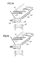
- Figs. 13 to 15 the disposition below the gate 81 is shown modified, a separating grate 102 being provided, similar to that indicated by 51 to make the granulated material fall on an inclined plane 104 being below the granulated material which thus falls onto the conveyor 85; the bullets retained by the grate 102 fall therealong to be collected into a container 106 similar to that indicated by 55.
Landscapes
- Engineering & Computer Science (AREA)
- General Engineering & Computer Science (AREA)
- Aiming, Guidance, Guns With A Light Source, Armor, Camouflage, And Targets (AREA)
- Lasers (AREA)
- Vibration Dampers (AREA)
Claims (20)
Priority Applications (1)
| Application Number | Priority Date | Filing Date | Title |
|---|---|---|---|
| AT86830374T ATE42825T1 (de) | 1985-12-20 | 1986-12-16 | Kugelfanganlage mit energieabsorbierender trennwand fuer schiessstaende. |
Applications Claiming Priority (4)
| Application Number | Priority Date | Filing Date | Title |
|---|---|---|---|
| IT955185 | 1985-12-20 | ||
| IT09551/85A IT1201402B (it) | 1985-12-20 | 1985-12-20 | Setto abbattitore di energia per proiettili,da installare in poligoni di tiro |
| IT09395/86A IT1204061B (it) | 1986-05-16 | 1986-05-16 | Parapalle con strato di granuli assorbenti,per poligoni di tiro,balipedi ed altro |
| IT939586 | 1986-05-16 |
Publications (2)
| Publication Number | Publication Date |
|---|---|
| EP0227612A1 EP0227612A1 (de) | 1987-07-01 |
| EP0227612B1 true EP0227612B1 (de) | 1989-05-03 |
Family
ID=26326201
Family Applications (1)
| Application Number | Title | Priority Date | Filing Date |
|---|---|---|---|
| EP86830374A Expired EP0227612B1 (de) | 1985-12-20 | 1986-12-16 | Kugelfanganlage mit energieabsorbierender Trennwand für Schiessstände |
Country Status (5)
| Country | Link |
|---|---|
| US (1) | US4786059A (de) |
| EP (1) | EP0227612B1 (de) |
| AT (1) | ATE42825T1 (de) |
| DE (1) | DE3663195D1 (de) |
| ES (1) | ES2008683B3 (de) |
Families Citing this family (36)
| Publication number | Priority date | Publication date | Assignee | Title |
|---|---|---|---|---|
| IT1211950B (it) * | 1987-12-03 | 1989-11-08 | Icos Impresa Constr | In particolare tiri in galleria perfezionamento nei fermapalle balistici ad autorigenerazione idonei a tiri con armi portatili e simili, |
| IT1231788B (it) * | 1989-05-22 | 1992-01-14 | Icos Impresa Constr | Gruppo di convogliamento e separazione in fermapalle balistici |
| GB2242730A (en) * | 1990-04-07 | 1991-10-09 | John Alan Vertanness | Bullet trap |
| US5848794A (en) | 1991-01-18 | 1998-12-15 | Caswell International Corporation | Granulate backstop assembly |
| GB2290370A (en) * | 1994-06-14 | 1995-12-20 | John Alan Vertanness | 'Encapsulator' dual-system bullet catcher for use in lead-free indoor ranges |
| WO1996010725A1 (en) * | 1994-09-30 | 1996-04-11 | Tovarischestvo S Ogranichennoi Otvetstvennostiu 'anter Ltd.' | Target |
| US6173956B1 (en) | 1996-09-27 | 2001-01-16 | O.M.F. Inc. | Projectile backstop assembly |
| CH691409A5 (de) * | 1996-12-13 | 2001-07-13 | Schweizerische Unternehmung Fu | Kugelfang und Entsorgungseinrichtung für einen Kugelfang. |
| US5907930A (en) * | 1997-11-26 | 1999-06-01 | Ricco, Sr.; John A. | Shooting range |
| US5901960A (en) * | 1998-01-13 | 1999-05-11 | Caswell International Corporation | Granulate-backstop assembly |
| US6311980B1 (en) * | 1999-09-28 | 2001-11-06 | Action Target, Inc. | Projectile retrieval system |
| US7140615B1 (en) * | 1999-09-28 | 2006-11-28 | Action Target, Inc. | Projectile retrieval system |
| US6378870B1 (en) | 1999-12-24 | 2002-04-30 | Action Target, Inc. | Apparatus and method for decelerating projectiles |
| RU2167383C1 (ru) * | 1999-12-27 | 2001-05-20 | Дочернее открытое акционерное общество "Ижевский оружейный завод" | Установка для сбора и разделения продуктов выстрела при испытаниях гладкоствольного оружия |
| US6533280B1 (en) | 2000-03-03 | 2003-03-18 | H. Addison Sovine | Bullet backstop assembly |
| US6588759B1 (en) | 2000-07-18 | 2003-07-08 | Action Target, Inc. | Target baffle bracket |
| US7194944B2 (en) | 2001-12-12 | 2007-03-27 | Action Target, Inc. | Bullet trap |
| US7775526B1 (en) | 2001-12-12 | 2010-08-17 | Action Target Inc. | Bullet trap |
| US7621209B2 (en) | 2002-07-12 | 2009-11-24 | Action Target Acquisition Crop. | Modular ballistic wall |
| US20050034594A1 (en) * | 2002-09-17 | 2005-02-17 | Parks Jimmy A. | Projectile retrieval system |
| US7354044B2 (en) * | 2002-12-02 | 2008-04-08 | The United States Of America As Represented By The Secretary Of The Navy | Partitioned particulate bullet trap |
| US6715761B1 (en) * | 2003-03-14 | 2004-04-06 | Gerth Moberg | Apparatus for shooting ranges |
| RU2239772C1 (ru) * | 2003-05-15 | 2004-11-10 | Общество с ограниченной ответственностью Научно-производственное предприятие "ОЗОН-Т" | Устройство для улавливания пули |
| US20060107985A1 (en) * | 2004-04-13 | 2006-05-25 | Sovine H A | Modular shoot house facility |
| US8469364B2 (en) | 2006-05-08 | 2013-06-25 | Action Target Inc. | Movable bullet trap |
| SE532678C2 (sv) * | 2007-09-11 | 2010-03-16 | Erlandssons Ind Ab Med Bi The | Ett kulfång med snedställda plåtar |
| JP5525309B2 (ja) * | 2010-03-31 | 2014-06-18 | 株式会社野村総合研究所 | 停弾装置 |
| US8827273B2 (en) | 2010-08-02 | 2014-09-09 | Action Target Inc. | Clearing trap |
| US8162321B1 (en) | 2011-07-18 | 2012-04-24 | Shank Jr John Mohr | Bullet trap |
| SE536516C2 (sv) * | 2012-06-04 | 2014-01-21 | Stapp Internat Ab | Urlakningsskydd för skjutbanor utomhus |
| US10619980B2 (en) * | 2015-01-16 | 2020-04-14 | Action Target Inc. | Dust containment unit manifold |
| US10240903B2 (en) * | 2016-01-14 | 2019-03-26 | Action Target Inc. | Projectile collection system |
| US10371489B2 (en) | 2016-01-15 | 2019-08-06 | Action Target Inc. | Bullet deceleration tray damping mechanism |
| US9897420B2 (en) * | 2016-01-15 | 2018-02-20 | Action Target Inc. | Bullet fragment collection tray |
| US10876821B2 (en) | 2017-01-13 | 2020-12-29 | Action Target Inc. | Software and sensor system for controlling range equipment |
| US12173993B2 (en) | 2018-12-24 | 2024-12-24 | Action Target Inc. | Dead stop assembly |
Family Cites Families (9)
| Publication number | Priority date | Publication date | Assignee | Title |
|---|---|---|---|---|
| GB190610992A (en) * | 1906-05-10 | 1906-06-21 | William Roden Orde | A Combined Butt and Bullet Catcher. |
| US2411026A (en) * | 1944-02-21 | 1946-11-12 | Douglas Aircraft Co Inc | Firing range butt |
| US2772092A (en) * | 1954-02-17 | 1956-11-27 | Nikoden Joseph | Bullet traps |
| US3737165A (en) * | 1970-08-31 | 1973-06-05 | Kory Ind Inc | Shooting range bullet trap structure |
| US3982761A (en) * | 1975-03-17 | 1976-09-28 | Devogelaere George E | Cantilevered pellet backstop |
| US4470604A (en) * | 1977-12-12 | 1984-09-11 | Hoffmann Anton R | Target practice system |
| GB2065277B (en) * | 1979-12-12 | 1983-05-11 | Laspo Ag | Firing butt |
| DE3212781A1 (de) * | 1982-04-06 | 1983-10-06 | Gfl Sportstaettenbau Gmbh | Kugelfang, insbesondere fuer solche schiessanlagen, die in geschlossenen raeumen angelegt sind |
| EG16973A (en) * | 1984-06-01 | 1993-12-30 | Impressa Construzioni Soc Fra | Ballistic projectile arrester, having a generation and or recovery system for the impact material swited to fires with small arms or others, in particular in indoors firing grounds |
-
1986
- 1986-12-16 ES ES86830374T patent/ES2008683B3/es not_active Expired
- 1986-12-16 DE DE8686830374T patent/DE3663195D1/de not_active Expired
- 1986-12-16 AT AT86830374T patent/ATE42825T1/de not_active IP Right Cessation
- 1986-12-16 US US06/942,501 patent/US4786059A/en not_active Expired - Fee Related
- 1986-12-16 EP EP86830374A patent/EP0227612B1/de not_active Expired
Also Published As
| Publication number | Publication date |
|---|---|
| ATE42825T1 (de) | 1989-05-15 |
| DE3663195D1 (en) | 1989-06-08 |
| EP0227612A1 (de) | 1987-07-01 |
| US4786059A (en) | 1988-11-22 |
| ES2008683B3 (es) | 1989-08-01 |
Similar Documents
| Publication | Publication Date | Title |
|---|---|---|
| EP0227612A1 (de) | Kugelfanganlage mit energieabsorbierender Trennwand für Schiessstände | |
| EP0186682B1 (de) | Kugelfang mit einrichtungen zum regenerieren des geschossauffangenden materials | |
| US4919437A (en) | Self-regeneration ballistic projectile-arrester | |
| US6173956B1 (en) | Projectile backstop assembly | |
| US4365719A (en) | Radiometric ore sorting method and apparatus | |
| Doroszuk et al. | Analysis of conveyor belt wear caused by material acceleration in transfer stations | |
| CN111617987A (zh) | 一种用于煤炭的智能自动分选系统 | |
| US5085765A (en) | Conveying and separation unit for ballistic projectile arresters | |
| US2411026A (en) | Firing range butt | |
| US4865720A (en) | Debris separator system | |
| US3946950A (en) | Material reducer | |
| US3936004A (en) | Material reducer | |
| CN115025997B (zh) | 一种煤矸分选装置及使用方法 | |
| CN206051043U (zh) | 斗轮式取料机防漏料装置 | |
| CA1064451A (en) | Material reducer | |
| RU2272148C1 (ru) | Рудоспуск | |
| CN116371517B (zh) | 一种井下采矿碎石安全输送装置及其输送方法 | |
| RU2564715C1 (ru) | Бесситное устройство для предварительной классификации по крупности угля и руд | |
| RU2167383C1 (ru) | Установка для сбора и разделения продуктов выстрела при испытаниях гладкоствольного оружия | |
| RU2229026C1 (ru) | Способ закладки выработанного пространства | |
| SU818995A1 (ru) | Амортизирующий полочный спуск | |
| CN207192218U (zh) | 一种垃圾炉渣缓冲装置 | |
| JPH0520680B2 (de) | ||
| EP0405616A2 (de) | Geschossfangvorrichtung mit einem Rücklauf- und Wiedergewinnungssystem für das geschossbremsende Material | |
| CN218753346U (zh) | 一种料斗装置 |
Legal Events
| Date | Code | Title | Description |
|---|---|---|---|
| PUAI | Public reference made under article 153(3) epc to a published international application that has entered the european phase |
Free format text: ORIGINAL CODE: 0009012 |
|
| AK | Designated contracting states |
Kind code of ref document: A1 Designated state(s): AT BE CH DE ES FR GB LI NL SE |
|
| 17P | Request for examination filed |
Effective date: 19870917 |
|
| 17Q | First examination report despatched |
Effective date: 19880519 |
|
| GRAA | (expected) grant |
Free format text: ORIGINAL CODE: 0009210 |
|
| AK | Designated contracting states |
Kind code of ref document: B1 Designated state(s): AT BE CH DE ES FR GB LI NL SE |
|
| PG25 | Lapsed in a contracting state [announced via postgrant information from national office to epo] |
Ref country code: SE Effective date: 19890503 Ref country code: NL Effective date: 19890503 |
|
| REF | Corresponds to: |
Ref document number: 42825 Country of ref document: AT Date of ref document: 19890515 Kind code of ref document: T |
|
| REF | Corresponds to: |
Ref document number: 3663195 Country of ref document: DE Date of ref document: 19890608 |
|
| ET | Fr: translation filed | ||
| NLV1 | Nl: lapsed or annulled due to failure to fulfill the requirements of art. 29p and 29m of the patents act | ||
| PG25 | Lapsed in a contracting state [announced via postgrant information from national office to epo] |
Ref country code: AT Effective date: 19891216 |
|
| PG25 | Lapsed in a contracting state [announced via postgrant information from national office to epo] |
Ref country code: ES Free format text: LAPSE BECAUSE OF THE APPLICANT RENOUNCES Effective date: 19891218 |
|
| PG25 | Lapsed in a contracting state [announced via postgrant information from national office to epo] |
Ref country code: LI Effective date: 19891231 Ref country code: CH Effective date: 19891231 Ref country code: BE Effective date: 19891231 |
|
| PLBE | No opposition filed within time limit |
Free format text: ORIGINAL CODE: 0009261 |
|
| STAA | Information on the status of an ep patent application or granted ep patent |
Free format text: STATUS: NO OPPOSITION FILED WITHIN TIME LIMIT |
|
| 26N | No opposition filed | ||
| BERE | Be: lapsed |
Owner name: ABC APPALTI BONIFICHE E COSTRUZIONI DI ELIO FLORI Effective date: 19891231 |
|
| PG25 | Lapsed in a contracting state [announced via postgrant information from national office to epo] |
Ref country code: FR Effective date: 19900831 |
|
| REG | Reference to a national code |
Ref country code: CH Ref legal event code: PL |
|
| PG25 | Lapsed in a contracting state [announced via postgrant information from national office to epo] |
Ref country code: DE Effective date: 19900901 |
|
| REG | Reference to a national code |
Ref country code: FR Ref legal event code: ST |
|
| PG25 | Lapsed in a contracting state [announced via postgrant information from national office to epo] |
Ref country code: GB Effective date: 19901216 |
|
| GBPC | Gb: european patent ceased through non-payment of renewal fee | ||
| REG | Reference to a national code |
Ref country code: ES Ref legal event code: FD2A Effective date: 20010402 |