EP0227613A2 - Ensemble de propulsion comportant une masselotte - Google Patents
Ensemble de propulsion comportant une masselotte Download PDFInfo
- Publication number
- EP0227613A2 EP0227613A2 EP86830375A EP86830375A EP0227613A2 EP 0227613 A2 EP0227613 A2 EP 0227613A2 EP 86830375 A EP86830375 A EP 86830375A EP 86830375 A EP86830375 A EP 86830375A EP 0227613 A2 EP0227613 A2 EP 0227613A2
- Authority
- EP
- European Patent Office
- Prior art keywords
- unit
- platform
- housing
- mass
- assembly according
- Prior art date
- Legal status (The legal status is an assumption and is not a legal conclusion. Google has not performed a legal analysis and makes no representation as to the accuracy of the status listed.)
- Withdrawn
Links
Images


Classifications
-
- F—MECHANICAL ENGINEERING; LIGHTING; HEATING; WEAPONS; BLASTING
- F01—MACHINES OR ENGINES IN GENERAL; ENGINE PLANTS IN GENERAL; STEAM ENGINES
- F01B—MACHINES OR ENGINES, IN GENERAL OR OF POSITIVE-DISPLACEMENT TYPE, e.g. STEAM ENGINES
- F01B9/00—Reciprocating-piston machines or engines characterised by connections between pistons and main shafts, not specific to groups F01B1/00 - F01B7/00
- F01B9/04—Reciprocating-piston machines or engines characterised by connections between pistons and main shafts, not specific to groups F01B1/00 - F01B7/00 with rotary main shaft other than crankshaft
- F01B9/06—Reciprocating-piston machines or engines characterised by connections between pistons and main shafts, not specific to groups F01B1/00 - F01B7/00 with rotary main shaft other than crankshaft the piston motion being transmitted by curved surfaces
-
- F—MECHANICAL ENGINEERING; LIGHTING; HEATING; WEAPONS; BLASTING
- F03—MACHINES OR ENGINES FOR LIQUIDS; WIND, SPRING, OR WEIGHT MOTORS; PRODUCING MECHANICAL POWER OR A REACTIVE PROPULSIVE THRUST, NOT OTHERWISE PROVIDED FOR
- F03G—SPRING, WEIGHT, INERTIA OR LIKE MOTORS; MECHANICAL-POWER PRODUCING DEVICES OR MECHANISMS, NOT OTHERWISE PROVIDED FOR OR USING ENERGY SOURCES NOT OTHERWISE PROVIDED FOR
- F03G7/00—Mechanical-power-producing mechanisms, not otherwise provided for or using energy sources not otherwise provided for
- F03G7/10—Alleged perpetua mobilia
- F03G7/125—Alleged perpetua mobilia creating a thrust by violating the principle of momentum conservation
Definitions
- the object of the invention is to provide a propulsor assembly apt to generate high thrusts. It comprises in combination: a mobile housing to which at least a unit with platform is combined, rotating relative to the housing about an axis orthogonal to the assembly advancement direction, the rotation of said unit causing the movement in radial direction of a centrifugal mass or "ram" which cyclically brings itself in correspondence of the direction of said advancement, said unit with platform being driven into rotation by a motor and said unit being accelerated and decelerated in its rotation; and means to obtain a thrust on said mobile housing, owing to the reaction provided by said centrifugal mass.
- the propulsor assembly comprises a housing with which at least a member apt to deliver energy and having the form of a cylinder-piston system is combined, such system being able to give rise to a thrust and reaction action according to an advancement direction, and at least a unit with platform, rotating relative to the housing about an axis transverse to said direction of advancement of said member and of said thrust, and the rotation of which unit causes the movement in radial direction of a centrifugal mass or "ram" which cyclically brings itself in correspondence of the direction of said thrust and on which the piston reaction is discharged, thereby the corresponding thrust is unidirectionally transmitted by said member to the housing; said unit with platform is made to rotate by its own independent motor, a return cam being provided solid with the housing to recall said mass whenever this is at a position far from said member.
- the unit is accelerated in its rotation prior to the discharge phase of the reaction onto the mass and is decelerated after such a phase, in order to limit the reverse displacement
- the assembly may comprise a dual clutch between said rotating unit and its motor, to impose the two speeds, and a brake to reduce said speed after the reaction on said mass.
- the assembly may also comprise a means for operating the unit for the acceleration, which is engaged and disengaged in synchronism with the unit to make it run at the highest velocity, respectively to consent its deceleration; after the deceleration, the unit is driven into rotation at a slowed down speed and it is provided with a free-wheel (or similar) system, to allow its acceleration; a brake is provided for the deceleration after the reaction on said mass.
- the present assembly may include a rotor provided with several pairs of units having a star arrangement, and one, two or more members apt to create energy; to said rotor, actuation means are associated for operating said pairs of units for the acceleration, synchronously movable with the rotor advancements, in order to take up an active condition and a passive condition.
- the two unit-operating means act each time on a pair of units for the acceleration of the eccentric masses and then move away therefrom to consent - through an angular displacement of the rotor - the replacement of a pair of units with the next one: said operating means move along the rotor axis in a reciprocating way.
- Eccentric means are provided to operate the compression in the cylinder/piston systems which are the members apt to create energy, being operated in synchronism with the rotor in order to act each time a unit moves away from its active position on said members.
- the propulsor assembly comprises retention means for retaining said centrifugal mass during an acceleration phase of said platform, which retention means are driven for releasing said centrifugal mass in correspondence of a predetermined angular orientation - relative to the advancement direction - and in correspondence of a predetermined angular velocity of rotation reached by the platform and detected by suitable tachymetric devices, the release of said mass causing the impact thereof against a part of said housing and yielding up a corresponding share of energy thereto and thus causing the advancement thereof, a return cam being fixedly predisposed relative to the housing to bring said centrifugal mass back towards the centre of said unit, while the platform is decelerated.
- Said retention means may comprise in combination a pair of stems each driven by a pinion and rack system, said pinion being operated by a cyilnder-piston device whose intervention is controlled by said tachymetric devices.
- the motor may be either an electric self-braking motor or an internal combustion engine, in the latter case braking means being provided to decelerate said platform.
- a plurality of unit with platform and centrifugal mass may be provided around a common rotating support so as to be successively presented in front of the part of said housing intended to receive the impact of the centrifugal masses of each unit.
- a main motor operates, through independent transmissions, the movement of said common rotating support as well as the rotation of the individual platforms of each unit, friction wheels with mobile axes allowing the engagement of the platform with the transmission for the acceleration phases and the disengagement of the platform for the deceleration phases, respectively.
- said friction wheels having mobile axes are carried by oscillating arms, a homokinetic joint permitting the oscillation of the transmission.
- numeral 1 generically indicates a housing making part of a carriage-like frame provided with bearing wheels 3 for the reaction on the ground. Such a disposition allows that the assembly carried by the housing 1 can be considered an open assembly.
- An internal combustion cylinder-piston system (like that of a two stroke engine) is provided as the member for the delivery of energy, of which system numeral 5 indicates the cylinder, provided with a head 5A, and numeral 7 indicates the piston.
- the piston has a stem 7A which moves along with the piston according to the thrust and advancement direction; in particular, the stem 7A is articulated to a carriage 9, which is guided by stems 10 thereof sliding within sleeves 12A,12B.
- the sleeves 12A and 12B are fixed to transverse beams 13A and 13B which, in turn, are secured to the housing 1 with which the cylinder 5 is solid.
- springs 14 are made to react in order to move the piston 7 away from the head 5A, to determine the intake strokes and to produce the bearing pressure of tappets 16 having the form of wheels carried by the carriage 9; the tappets 16 coact with a cam 18 which rotates and acts on the carriage and thus the piston to determine the compression stroke of the piston towards the head 5A of the cylinder, in the manner described below.
- the carriage 9 of the piston in particular exhibits a surface 20 substantially transverse to the axis of the thrust and to the direction of motion of the piston 7, on which surface, a centrifugal mass or so-called "ram" reacts as indicated below.
- a rotating unit which comprises a platform 24 and a braking disc 26, also rotates about an axis defined by a shaft 22 orthogonal to the direction of advancement and stroke of the piston.
- the unit 24, 26 is driven, through a transmission 28, by an independent motor 30 which, via a reduction unit and gear box generally indicated by 32, may determine two different rotation speeds of the unit, through a double-clutch 34 which causes different velocity ratio between the motor and the unit 24, 26.
- Braking jaws 36 - whose functions are indicated below - cooperate with the braking disc 26.
- the unit 24, 26 carries, on the platform 24, guide means 38 which consent the sliding, according to a radial direction - in respect to the rotation axis of the assembly 24, 26 - of a centrifugal mass generally indicated by 40 and which comprises a heavy mass 42 constituting the so-called "ram" and a pair of guide stems 44 which slide on the guide means 38.
- a second mass or block 42A more internally located than that indicated by 42, makes part of the inertial centrifugal mass 40.
- the internal block 42A of the mass 42, 44 is provided with a side tappet 46 and an inner tappet 48.
- a cam-profile 50 - solid with the housing 1 - cooperates with the inner tappet 48 and tends to urge the centrifugal mass outwardly along a stretch extending from the axis of the advancement direction, indicated by the arrow f1, through an angle of about 90° in the direction of the angular displacement of the unit 24, 26, which rotates according to arrow f3.
- a cam 52 - being also solid with the housing 1 - cooperates with the side tappet 46 and tends to move the centrifugal mass made up of the members 42, 42A, 44 inwardly, that is, towards the axis defined by the shaft 22; this re-enter action is determined approximately along an arc opposite to the one representing the action zone of cam 50.
- the disposition of the above mentioned dual-speed transmission drive starting from the motor 30 and concerning the cams 50 and 52 that cooperate with the tappets 48 and 46 is such as to determine, in particular, the following actions.
- X-X representing the thrust direction of the energy generator cylinder-piston system, and thus the direction of movement of the housing 1 and of sliding of the carriage 9, the action of the cam 50 develops approximately from the axis X along an arc of about 90° in the direction of the arrow f3.
- the coupling of the transmission high speed takes place with the rotating unit, so that a great acceleration is obtained of the same unit and thus also of the centrifugal mass which then reaches at high speed the angular position indicated by B.
- the utilization of the centrifugal force accumulated by the mass 42, 42A, 44 takes place through a contact between the mass 42 and the transverse track 20 of the carriage 9, through wheels 42C or equivalent means providing a contact between the mass 42 and the track surface 20.
- centrifugal mass causes a reaction on the same mass, which opposes the withdrawal of piston 7 from the head 5A of the cylinder and determines thereby the advancement of the carriage solid with the housing 1, while the mass slides relative to its own slide guides 38.
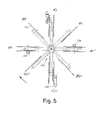
- Figs. 3 to 5 a solution is shown wherein there is a multiplication of the effects of the described system on every revolution performed by an equipment carrying a plurality of centrifugal masses on respective rotation axes.
- a pair of cylinder-piston systems having cylinders 105, heads 105A and pistons 107, is provided.
- the carriages 109 of the pistons 107 are solid with substantially transverse reaction surfaces 120 on which the centrifugal masses of an assembly of rotating units act in succession - each unit having a centrifugal mass - which masses follow one another in correspondence of the surfaces 120 to determine a fast succession of the functions of the two cylinder-piston systems 105, 107.
- an equipment 130 is provided driven into rotation by the motor 118 and formed by a star with eight arms (in the drawing) on each of which a rotating unit is disposed with a respective centrifugal mass.
- Each unit 132 has a rotating disc or platform which is operated with a slow rotation motion by a transmission 138 taking the motion from the shaft 116; this transmission is also provided with a free-wheel clutch system, allowing an acceleration of the equipment 132 of which the rotating platforms make part, so that each of them may be accelerated in respect to the speed of rotation imposed by its own transmission 138.
- Each rotating unit 132 can also be subjected to the action of a brake of its own, which decelerates the rotating unit until it is brought back to the slow rotation speed obtained by the transmission 138.
- each rotating unit 132 and thus of the centrifugal masses 134 associated thereto may be achieved through a fast transmission system made up of two discs being put into rotation at high speed by a suitable transmission drawn from the shaft 116 and thus from the motor 118, the two fast discs 150 being carried by an equipment axially movable in the direction of the double arrow f30, to move near to and away from the two units 132.
- a fast transmission system made up of two discs being put into rotation at high speed by a suitable transmission drawn from the shaft 116 and thus from the motor 118, the two fast discs 150 being carried by an equipment axially movable in the direction of the double arrow f30, to move near to and away from the two units 132.
- each unit 132 comprising a platform will be provided of fixed cams, like the cams 50 and 52 already described in the preceding example for the inwards approach movement and for the outwards displacement of the masses 134 respectively in correspondence of the deceleration and acceleration zones.
- the solution of Figs. 3 to 5 allows a multiplication of the effects that can be obtained by the solution providing a single member 5, 7 apt to deliver energy, only one rotating platform and a single centrifugal mass 40, 42, 44, shown in Figs. 1 and 2.
- the two members capable of delivering energy that is, the two cylinder-piston systems 105, 107 give rise, upon each contemporaneous ignition and expansion phase thereof - to a thrust caused by the high pressure gases onto the heads 105A of the cylinders 105, and thus to an advancement thrust, in the direction of arrow f10, which is transmitted to the structure 101 forming a carriage with wheels 103.
- the centrifugal masses 134 are made to operate on the surfaces 120 of each carriage 109, in the condition in which they find themselves at positions A1 and A1 ⁇ of the star equipment 130 in Fig. 5, that is, in a situation of maximum acceleration.
- maximum acceleration is obviously due to the properly timed accelerating action arising from the approach and contact of discs 150 with platforms 132.
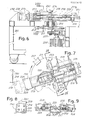
- numeral 201 indicates a carriage housing on which the assembly according to the invention is applied.
- An individual platform unit comprises a platform 203 driven into rotation by a motor 205 through a transmission 207 and a shaft 209; on said shaft 209, a disc 211 is fitted that is keyed for the actuation of possible brake jaws 212 capable of decelerating the platform 203.
- a guide 213 is applied within which four stems 214 slide being associated with a centrifugal mass 215 (ram) which is thus able to slide between two end positions of maximum approach to the rotation axis of the platform and of maximum distance therefrom, these positions being shown respectively by a solid line and a dotted line in Figs. 6 and 7.
- the stems 214 drag along a black 216 to which another stem 217 is connected on which a cylinder 218 is located for the purposes described below.
- Stems 221 of pinion-rack retention means 223 retain the mass 215 at a position close to the rotation axis by acting on the shoulder defined by said cylinder 218, said retention means 223 being operated by cylinder-piston systems 225.
- the stems 221 are driven by the cylinder-piston systems 225 in order to be released, they move back instantaneously thus releasing the stem 217, then tend to draw near again.
- the engagement with the shoulder provided by the cylinder 218 is possible, however, only when the centrifugal mass 215 has come back to the original position prior to the release, owing to the action of the return means to be described later.
- a compression spring 224 acting between a portion 226 of the platform 203 and a shoulder 217A of the stem 217, operates an initial thrust to the centrifugal mass 215 after the release by the stems 221.
- the centrifugal mass 215 is also associated: with a roller 227 which acts as a tappet on a cam 229 solid with said housing 201 to return the centrifugal mass 215 as described below; and with two further rollers 228 apt to roll on a portion of the housing 201 as described below.
- the centrifugal mass 215 is initially retained, in order to be engaged through the means 223 with the platform 203, in the vicinity of the rotation axis thereof, and is driven into rotation and accelerated by the motor 205.
- a suitable control circuit acts on the cylinder-piston systems 225 which release the retention means 223 thereby releasing the centrifugal mass 215.
- This mass by receiving an initial thrust from the spring 224, is further accelerated by the centrifugal force to which it is subjected and strikes against a portion 230 of the housing 201, the release of the mass 215 taking place when the platform 203 finds itself at a predetermined position in respect to the housing 201 and in such a way as to cause the impact of the mass 215 onto the portion 230 of said housing 201.
- the rollers 228 allow the centrifugal mass 215 to be rolled onto the portion 230 of the housing 201 after the impact.
- the centrifugal mass 215 Upon the impact, the centrifugal mass 215 gives up a share of its own energy to the housing 201 thereby urging it to move in the direction of the same impact.
- the platform 203 is slowed down by the action of the motor 205 -if a self-braking motor is used - and/or by the action of braking jaws 212 acting upon the disc 211.
- the roller 227 As the platform 203 and the mass 215 keep on rotating, the roller 227 is made to engage on the cam 229 which is solid with the housing, and the mass 215 is then brought back towards the rotation axis of the platform 203.
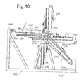
- a plurality of assemblies 235 may be mounted in a variable number on a common support with a single motor, as shown by the schematic ensemble view on Fig. 6.
- a support 240 applied to the housing 201A four arms 241 each carrying an assembly 235 similar to that of Figs. 6 and 7, are fitted; the assemblies 235 are operated by a single motor 243 by a transmission system to be described below.
- the motor 243 operates also the rotation of the support 240 about its own axis, so that the assemblies 235 are cyclically brought in front of a portion 245 of the housing 201A, the centrifugal masses 215 of each assembly 235 being made to impact onto said portion 245.
- the motor 243 operates the rotation of the support 240 through a belt 247 and a pulley 248, and the rotation of a shaft 251, housed in said support 240, through a belt 249 and a pulley 250.
- gears 253 are mounted from which the motion is taken via other gears 255 mounted on small shafts 257 idly rotating on bearings 259.
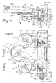
- Two pairs of gears 253, 255 are associated with each assembly 235 as shown in particular in Fig. 12.
- a bevel gear 260 is mounted which transmits the motion, through the bevel gear 261 meshing therewith, to a shaft 263 made up of two sections with the interposition of a homokinetic joint 265 (Fig. 11).
- a pair of bevel gears 267, 269 transmits the motion to a friction wheel 271 mounted on an arm 272 oscillating about an articulation 274.
- Two friction wheels 271 for each assembly 235 accelerate, through another friction wheel 273, the platform 203 of a unit equivalent to that of Figs. 6 and 7, said wheel 273 being fitted, that is keyed, on the rotation shaft of the platform 203.
- the centrifugal mass 215 is released so as to move and strike against said portion 245.
- the platform is slowed down by braking jaws 275 which act on the same wheel 273 or on a suitable disc mounted on the platform axis.
- the friction wheels 271 are moved away from the wheel 273 by causing the arms 272 to oscillate about the articulations 274 - according to arrow f71 - by means of cylinder-piston systems 276 carried by appendixes 277 being solid with the support 240.
Landscapes
- Engineering & Computer Science (AREA)
- Chemical & Material Sciences (AREA)
- Combustion & Propulsion (AREA)
- Mechanical Engineering (AREA)
- General Engineering & Computer Science (AREA)
- One-Way And Automatic Clutches, And Combinations Of Different Clutches (AREA)
- Centrifugal Separators (AREA)
Applications Claiming Priority (2)
| Application Number | Priority Date | Filing Date | Title |
|---|---|---|---|
| IT09548/85A IT1201400B (it) | 1985-12-17 | 1985-12-17 | Complesso propulsore con massa centrifuga offrente reazione di spinta |
| IT954885 | 1985-12-17 |
Publications (2)
| Publication Number | Publication Date |
|---|---|
| EP0227613A2 true EP0227613A2 (fr) | 1987-07-01 |
| EP0227613A3 EP0227613A3 (fr) | 1988-12-14 |
Family
ID=11132024
Family Applications (1)
| Application Number | Title | Priority Date | Filing Date |
|---|---|---|---|
| EP86830375A Withdrawn EP0227613A3 (fr) | 1985-12-17 | 1986-12-16 | Ensemble de propulsion comportant une masselotte |
Country Status (2)
| Country | Link |
|---|---|
| EP (1) | EP0227613A3 (fr) |
| IT (1) | IT1201400B (fr) |
Cited By (4)
| Publication number | Priority date | Publication date | Assignee | Title |
|---|---|---|---|---|
| FR2626320A1 (fr) * | 1988-01-22 | 1989-07-28 | Bertolucci Paul | Dispositif generateur de poussee interne |
| EP0360764A3 (fr) * | 1988-09-21 | 1991-05-29 | Rino Calzolari | Appareil capable de convertir un mouvement rotatif en mouvement linéaire pour l'avancement d'un véhicule autopropulsé |
| FR2749631A1 (fr) * | 1996-06-07 | 1997-12-12 | Vaillant Christian | Dispositif a inertie et a controle d'intensite et de vitesse destine a produire des forces et couples variables |
| ITUB20152140A1 (it) * | 2015-07-13 | 2017-01-13 | Sante Taglioni | Dispositivo motore |
Families Citing this family (1)
| Publication number | Priority date | Publication date | Assignee | Title |
|---|---|---|---|---|
| IT202000027176A1 (it) * | 2020-11-12 | 2022-05-12 | Sante Taglioni | Spintore ibrido |
Family Cites Families (3)
| Publication number | Priority date | Publication date | Assignee | Title |
|---|---|---|---|---|
| FR715287A (fr) * | 1930-04-25 | 1931-11-28 | Procédé et dispositif pour imprimer aux corps un mouvement de translation | |
| FR2129022A5 (fr) * | 1971-03-11 | 1972-10-27 | Estrade Fernand | |
| IT1198526B (it) * | 1983-02-09 | 1988-12-21 | Rino Calzolari | Propulsore con elevate azioni di spinta comprendente un organo di spinta quale motore a combustione interna o simile |
-
1985
- 1985-12-17 IT IT09548/85A patent/IT1201400B/it active
-
1986
- 1986-12-16 EP EP86830375A patent/EP0227613A3/fr not_active Withdrawn
Cited By (4)
| Publication number | Priority date | Publication date | Assignee | Title |
|---|---|---|---|---|
| FR2626320A1 (fr) * | 1988-01-22 | 1989-07-28 | Bertolucci Paul | Dispositif generateur de poussee interne |
| EP0360764A3 (fr) * | 1988-09-21 | 1991-05-29 | Rino Calzolari | Appareil capable de convertir un mouvement rotatif en mouvement linéaire pour l'avancement d'un véhicule autopropulsé |
| FR2749631A1 (fr) * | 1996-06-07 | 1997-12-12 | Vaillant Christian | Dispositif a inertie et a controle d'intensite et de vitesse destine a produire des forces et couples variables |
| ITUB20152140A1 (it) * | 2015-07-13 | 2017-01-13 | Sante Taglioni | Dispositivo motore |
Also Published As
| Publication number | Publication date |
|---|---|
| EP0227613A3 (fr) | 1988-12-14 |
| IT1201400B (it) | 1989-01-27 |
| IT8509548A0 (it) | 1985-12-17 |
Similar Documents
| Publication | Publication Date | Title |
|---|---|---|
| US4567781A (en) | Steady power | |
| KR100760324B1 (ko) | 엔진 | |
| EP0227613A2 (fr) | Ensemble de propulsion comportant une masselotte | |
| US5983845A (en) | Rotational motion mechanism and engine | |
| US6036461A (en) | Expansible chamber device having rotating piston braking and rotating piston synchronizing systems | |
| US20180326683A1 (en) | Mechanical press with sliding block | |
| SE433869B (sv) | Anordning for kompensering av masskrafter vid indexeringsrorelse hos ett maskinorgan | |
| US5028044A (en) | Rotary feeder for blanks | |
| US20060060012A1 (en) | Centrifugal lifting system | |
| US5176036A (en) | Parallel shaft drive and indexing machine | |
| US5094327A (en) | Apparatus for coupling a working-station shaft of a packaging machine to a main drive shaft thereof | |
| EP0728666B1 (fr) | Convoyeur avec parcours circulaire, spécialement pour groupes d'objets fragiles cylindriques et utilisé dans des machines d'emballage de cigarettes ou similaires | |
| RU2465474C2 (ru) | Двигатель внутреннего сгорания и привод распределительного вала | |
| CN101850848A (zh) | 一种飞轮动力安全发射方法及装置 | |
| SU432706A3 (ru) | Механизм переноса заготовок кмногопознционным высадочным прессам-автоматам | |
| CN102717895A (zh) | 一种连续弹射弹射器 | |
| CN202686773U (zh) | 一种连续弹射弹射器 | |
| JPH0223461B2 (fr) | ||
| JPH1122804A (ja) | 割り出し装置 | |
| CN113790250A (zh) | 一种机械式无级变速方法及装置 | |
| SU471975A1 (ru) | Привод сварочного пресса | |
| SU789194A1 (ru) | Молот | |
| CN1216486A (zh) | 旋转成形装置及旋转成形方法 | |
| US20190024645A1 (en) | Method to Form Impulse Jet | |
| RU2124643C1 (ru) | Способ работы роторно-лопастного двигателя или машины внутреннего сгорания и устройство для его осуществления |
Legal Events
| Date | Code | Title | Description |
|---|---|---|---|
| PUAI | Public reference made under article 153(3) epc to a published international application that has entered the european phase |
Free format text: ORIGINAL CODE: 0009012 |
|
| AK | Designated contracting states |
Kind code of ref document: A2 Designated state(s): AT BE CH DE ES FR GB LI SE |
|
| PUAL | Search report despatched |
Free format text: ORIGINAL CODE: 0009013 |
|
| AK | Designated contracting states |
Kind code of ref document: A3 Designated state(s): AT BE CH DE ES FR GB LI SE |
|
| STAA | Information on the status of an ep patent application or granted ep patent |
Free format text: STATUS: THE APPLICATION IS DEEMED TO BE WITHDRAWN |
|
| 18D | Application deemed to be withdrawn |
Effective date: 19890703 |