EP0227875A1 - Schrägstellbare Chargiereinrichtung für geschmolzenes Metall beim Giessen mit Zwangskühlung - Google Patents
Schrägstellbare Chargiereinrichtung für geschmolzenes Metall beim Giessen mit Zwangskühlung Download PDFInfo
- Publication number
- EP0227875A1 EP0227875A1 EP86100065A EP86100065A EP0227875A1 EP 0227875 A1 EP0227875 A1 EP 0227875A1 EP 86100065 A EP86100065 A EP 86100065A EP 86100065 A EP86100065 A EP 86100065A EP 0227875 A1 EP0227875 A1 EP 0227875A1
- Authority
- EP
- European Patent Office
- Prior art keywords
- molten metal
- stool
- inclining
- casting
- cooling
- Prior art date
- Legal status (The legal status is an assumption and is not a legal conclusion. Google has not performed a legal analysis and makes no representation as to the accuracy of the status listed.)
- Granted
Links
- 238000005266 casting Methods 0.000 title claims abstract description 89
- 229910052751 metal Inorganic materials 0.000 title claims abstract description 81
- 239000002184 metal Substances 0.000 title claims abstract description 81
- 238000001816 cooling Methods 0.000 title claims abstract description 74
- 239000002826 coolant Substances 0.000 claims abstract description 38
- 238000007664 blowing Methods 0.000 claims abstract description 4
- 239000002893 slag Substances 0.000 claims description 8
- 230000001846 repelling effect Effects 0.000 claims description 2
- 238000005096 rolling process Methods 0.000 claims description 2
- 238000007599 discharging Methods 0.000 claims 1
- 238000007711 solidification Methods 0.000 abstract description 16
- 230000008023 solidification Effects 0.000 abstract description 16
- 230000000694 effects Effects 0.000 abstract description 3
- 238000000034 method Methods 0.000 description 15
- 239000004576 sand Substances 0.000 description 5
- 230000007423 decrease Effects 0.000 description 2
- 239000012535 impurity Substances 0.000 description 2
- 230000007847 structural defect Effects 0.000 description 2
- 229910000838 Al alloy Inorganic materials 0.000 description 1
- 229910052782 aluminium Inorganic materials 0.000 description 1
- XAGFODPZIPBFFR-UHFFFAOYSA-N aluminium Chemical compound [Al] XAGFODPZIPBFFR-UHFFFAOYSA-N 0.000 description 1
- 230000006835 compression Effects 0.000 description 1
- 238000007906 compression Methods 0.000 description 1
- 230000007547 defect Effects 0.000 description 1
- 238000009434 installation Methods 0.000 description 1
- 239000000203 mixture Substances 0.000 description 1
- 238000012986 modification Methods 0.000 description 1
- 230000004048 modification Effects 0.000 description 1
- 230000001737 promoting effect Effects 0.000 description 1
- 230000001681 protective effect Effects 0.000 description 1
- XLYOFNOQVPJJNP-UHFFFAOYSA-N water Substances O XLYOFNOQVPJJNP-UHFFFAOYSA-N 0.000 description 1
Images

Classifications
-
- B—PERFORMING OPERATIONS; TRANSPORTING
- B22—CASTING; POWDER METALLURGY
- B22D—CASTING OF METALS; CASTING OF OTHER SUBSTANCES BY THE SAME PROCESSES OR DEVICES
- B22D15/00—Casting using a mould or core of which a part significant to the process is of high thermal conductivity, e.g. chill casting; Moulds or accessories specially adapted therefor
- B22D15/04—Machines or apparatus for chill casting
-
- B—PERFORMING OPERATIONS; TRANSPORTING
- B22—CASTING; POWDER METALLURGY
- B22D—CASTING OF METALS; CASTING OF OTHER SUBSTANCES BY THE SAME PROCESSES OR DEVICES
- B22D15/00—Casting using a mould or core of which a part significant to the process is of high thermal conductivity, e.g. chill casting; Moulds or accessories specially adapted therefor
Definitions
- This invention relates to an inclining molten metal charging apparatus for forced cooling casting which uses chillers as forced cooling means for promoting directive solidification of castings, and moreover uses a tubular member as the forced cooling means when a through-hole(s) to be used for fastening a resulting casting by a bolt or the like is formed by internally chilling the tubular member in the casting.
- the solidification rate of the molten metal is low and the mechanical strength of the resulting castings is also low.
- the Applicant of the present invention previously proposed a direct cooling type casting method of casting (Japanese Patent Laid-Open No. 109559/1982) which provides a casting with an excess metal portion at the time of casting so that solidification occurs from the portions close to this excess metal portion, and forcedly cools the excess metal portion so as to promote directional solidification.
- This direct cooling type casting method of casting promotes directional solidification, improves the quality of resulting castings and shortens the casting cycle.
- the Applicant also proposed previously a forced cooling casting method (Japanese Patent Laid-Open No. 86966/1983) which disposes a tubular member, which is to be internally chilled in a resulting casting as a functional component whose hollow portion is to be used as a bolt fastening hole of the casting, for example, and passes a cooling medium through this tubular member to forcedly cool the molten metal and to promote solidification.
- This forced cooling casting method increases the solidification rate of the molten metal, improves the mechanical strength of the resulting casting and shortens the casting cycle.
- the yield of the resulting castings is less because the excess metal portion is disposed of, and removal of the excess metal portion after casting is very time-consuming.
- the Applicant of the invention proposed a forced cooling casting method (not yet disclosed) which utilizes chillers, which have often been used in the past, for directive solidification and utilizes also a tubular member, which is to be internally chilled in a resulting casting by a molten metal, for forced cooling.
- a cooling nozzle for supplying the cooling medium is fitted into the tubular member and supplies the cooling medium from the cooling nozzles into the tubular member. Therefore, unless the cooling nozzle fits the tubular member tightly, the cooling medium will leak, and it has been necessary to develop a method which can tightly and quickly fit the cooling nozzle to the tubular member.
- the inclining molten metal charging apparatus of the present invention to accomplish the object described above comprises a fixed frame; an inclining frame pivotally supported by the fixed frame and reciprocatingly inclined by a predetermined angle; a stool to which a casting mold, a chiller disposed in such a manner as to race the cavity of the casting mold and a tubular member disposed in such a manner as to pass through the cavity and to be internally chilled in a resulting casting as a functional component are located and fitted; stool support means for carrying the stool in and out from a space defined by the inclining frame; clamp means having a function of clamping the stool at a predetermined position inside the space described above, and including push means for pushing the casting mold towards the stool when the clamp means effects clamping; a molten metal vessel fixed to the inclining frame in such a manner that the molten metal inlet thereof faces a molten metal port of the casting mold, receiving the molten metal at the end of the forward movement of the inclining frame and completing the charge of the mol
- the top of the cooling nozzle fits or the upper end portion of the tubular member with the clamp of the stool at the predetermined position in the space.
- the connection of the cooling to the tubular member can be accurately and quickly made because the cooling nozzles is located in such a manner that the tip portion thereof corresponds to the upper end portion of the tubular member when the stool is at the predetermined position.
- the molten metal vessel is arranged in such a manner that its molten metal inlet faces the molten metal port of the casting mold when the mold is at the predetermined position. Therefore, the charging operation of the molten metal can be started immediately after completion of the clamping operation of the clamp means.
- the molten metal vessel is arranged so that it receives the molten metal at the end of the forward movement of the inclining frame and finishes the charge of molten metal at the end of the return movement. Therefore, charging operation of the molten metal can be accomplished extremely quickly. Since the molten metal vessel and the casting mold incline integrally with each other, their molten charge inlet and molten metal port do not come away from each other; therefore, the molten metal does not leak from between them. Moreover, since the casting mold is pushed to the stool by the push means during its inclining operation, the molten metal does not leak from the joint surface of the cope and drag of the casting mold and the charging operation of the molten metal is extremely accurate.
- the cooling nozzle has already been connected to the tubular member before the stool is clamped, and the chiller cooling means is disposed in such a manner as to be capable or blowing the cooling medium to the chillers. Therefore, the forced cooling step can be carried out immediately after completion of the reciprocating inclination of the inclining frame (that is, the completion of the charging operation of the molten metal), and hence this forced cooling step can be carried out quickly, too.
- the stool support means consists of a conveyor roller for defining a moving path of the stool, a stopper member abutting the front portion of the stool when the stool is carried into the space and guide rollers coming into rolling contact with both sides of the stool on both sides of the conveyor rollers, the stool can be positioned on the clamp means to some extent, so that the clamping operation can be carried out smoothly.
- the stopper is retractable with respect to the moving path of the stool and is withdrawn from its region when the stool is carried out, the moving direction of the stood can be made the same when it is carried in and when it is carried out. Therefore, the stool can be carried in and out smoothly.
- the stool is equipped with at least two guide pins projecting upwards and if the clamp means consists of a main body supported by the inclining frame and moved up and down in the space defined by the inclining frame and guide bushes disposed in such a manner as to correspond to the guide pins, fixed by the main body and fitting to the guide pins when the main body moves downward, the stool can be fixed more reliably to the inclining frame.
- the push means consists of a repelling spring
- leakage of molten metal from the joint surface of the casting mold can be prevented more reliably by selecting a suitable driving force for the spring.
- This slag removing means consists, for example, of a weir disposed close to the molten metal inlet.
- the cooling medium can be discarded or circulated automatically by furnishing the cooling medium tank with a cooling medium discharge pipe.
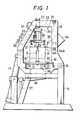
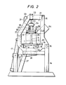
- FIGURES 1 through 3 are front views showing an inclining molten metal charging apparatus for forced cooling casting in accordance with one embodiment of the present invention, wherein:
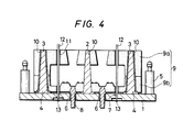
- reference numeral 1 represents a stool having a rectangular flat sheet-like shape.
- Three positioning pins 2, 3, 3 are implanted and fixed onto the stool 1. These positioning pins 2, 3, 3 are disposed at those positions which correspond to the apexes of an imaginary equilateral triangle described arbitrarily on the stool.
- the pin disposed at the position corresponding the apex at which the two equilaterals cross each other is a round pin 2 having a round cross-section while the other two positioning pins are square pins 3, 3, each having a rectangular cross-section.
- a mold horizontal positioning seat 4 for positioning a mold in a horizontal plane is disposed below these positioning pins 2, 3, 3.
- the round pin 2 has a conical shape whose diameter progressively decreases upwards, while each square pin 3 has a pyramid-like shape whose diameter similarly progressively decreases upwards.
- a pair of guide pins 5 are fitted at positions close to both ends or the stool 1 in its longitudinal direction.
- a plurality of holes are bored on the stool 1 for chillers which forcedly cools a molten metal and for fitting a plurality of tubular members.
- five holes 6, 8 are provided for each of the chillers and the tubular members. The chillers 8 are fitted into these holes 6.
- a sand mold 9 as a casting mold is inserted to these positioning pins 2, 3, 3 of the stool 1, and position and mold adjustment are then effected.
- the sand mold 9 consists of a cope 9a and a drag 9b, and locating pin holes 10 are bored in the cope 9a and in the drag 9b at positions corresponding to the locating pins 2, 3, 3, respectively.
- the hole corresponding to the round pin 2 has substantially the same size as the round pin while the holes corresponding to the square pins 3 have the same length as the square pins in the transverse direction of the stool 1 and are longer than the square pins 3 in the longitudinal direction. In other words, these holes have an elongated cross-section.
- a hole 11 for a tubular member is bored on the sand mold in order to insert a tubular member 12.
- the tubular member 12 is inserted into the hole 11.
- the lower end of the tubular member is supported by the ridge of a receiving bed 13 which has a substantially triangular cross-section and is mounted on the stool 1.
- reference numeral 14 represents a fixed frame which is assembled in a substantially rectangular shape and is fixed to a floor.
- An inclining frame 15 is mounted to this fixed frame 14.
- the inclining frame 15 is pivotally supported by the fixed frame 14 through a rotary shaft 16, and an inclining cylinder 17 as inclination driving means is rotatably fitted to a part of the fixed frame 14 on the opposite side to the rotary shaft 16.
- the tip of a rod of the inclining cylinder 17 is connected to part of the inclining frame 15. Therefore, the inclining frame 15 can be inclined freely by a predetermined angle by the inclining cylinder 17 with the rotary shaft 16 being the center.
- the stool 1 equipped with the mold described already is carried into and out from the space defined by the inclining frame 15.
- a conveyor roller 18 is disposed below the inclining frame 15 so as to transfer the stool 1 on this conveyor roller 18.
- Guide rollers 19 as support means for restricting the movement of the stool 1 in a direction crossing the transfer direction of the stool 1 at right angles, and a stopper 20 for stopping the movement of the stool 1 is disposed at a position which is substantially the same as that of the stool, in such a manner as to be able to be retracted freely.
- the conveyor roller 18, the guide roller 19 and the stopper 20 together constitute stool support means.
- Clamp means 21 is fitted to an upper portion of the inclining frame 15. This clamp means 21 will be explained below.
- a clamp cylinder 22 is vertically fitted to an upper portion of the inclining frame 15 in such a manner as to face downwards, and a clamp plate 23 is fitted to the tip of the clamp cylinder 22.
- a support pin 24 is inserted through the clamp plate 23 and supports a cooling plate main body 25 in a floating state.
- a plurality guide bushes 26 are disposed on the cooling plate main body 25 at positions corresponding to the guide pins 5 on the side of the stool 1, and push means 27 for pushing the stool 1 towards the mold 9 and supporting it is also provided.
- a hole for inserting the tubular member 12 is formed at a position corresponding to the tubular member hole 11 of the sand mold 9.
- a sleeve 28 for a cooling nozzle is fitted to the upper surface of the cooling plate main body 25 in such a manner as to correspond to this hole.
- a protective case 29 is fitted to an upper part of this sleeve 28 so as to set a spring and to support and guide the upper portion of the cooling nozzle main body.
- a cooling nozzle 30 is slidably inserted into this sleeve 28. The cooling nozzle 30 is connected to a conduit 31 for introducing a cooling medium.
- a flange is formed near the center of the cooling nozzle main body, and a compression spring 32 is interposed between the flange and the protection case 29 around the outer periphery of the cooling nozzle 30.
- the tip of the cooling nozzle 30 has a conical shape, and the diameter of the main body of the cooling nozzle 30 is substantially the same as that of the tubular member 12. Therefore, when the tip of the cooling nozzle 30 is inserted into the tubular member 12, the cooling nozzle 13 abuts the tubular member 12 while its tip is completely inserted.
- the conduit 31 is connected to a cooling medium supply head 33.
- a bill-like molten metal vessel 34 is fixed to the side of the inclining frame 15 with its tip facing the molten metal inlet of the mold 9.
- Reference numeral 34A represents the inlet which faces a port 9A of the mold 9.
- a weir 35 for removing slag is disposed inside the molten metal vessel 34.
- a cooling medium tank 36 for a cooling medium is disposed on the fixed frame 14 below the bottom of the inclining frame 15, and the cooling medium inside the cooling medium tank 36 is discharged outside the apparatus through a cooling medium discharge pipe 37. Furthermore, a cooling nozzle 38 as cooling means for cooling the chillers 8 is disposed inside the cooling medium tank 36.
- the stool 1 to which the casting mold 9, the chillers 8 and the tubular member 12 are ritted is transferred by the conveyor roller 18 into the inclining frame 15.
- the stool 1 is guided at its side portions by the guide rollers 19, and is stopped by the stopper 20 at a predetermined position.
- preliminary (i.e. tentative) position adjustment is made.
- the upper clamp means 21 is actuated.
- the clamp cylinder 22 starts extending to move down the cooling plate main body 25.
- the guide bush 26 and the guide pin 5 mesh with each other, thereby positioning the cooling plate main body 25 on the stool 1.
- the tip of the cooling nozzle 30 enters the tubular member 12 and is fitted thereto.
- the upper surface of the casting mold 9 is simultaneously pushed to and supported by the push member 27.
- the inclining cylinder 17 is actuated so that the inclining frame 15 is inclined with the rotary shaft 16 being the center until the upper surface of the molten metal vessel 34 becomes substantially horizontal as shown in FIGURE 3. In this state, a predetermined quantity of a molten metal is poured into the molten metal vessel 34.
- the inclining cylinder 17 is again actuated to release the inclination, whereby both the inclining frame 15 and the molten metal vessel 34 incline simultaneously and return to the state shown in FIGURE 2.
- the cooling medium is supplied from the cooling medium supply head 33 and is caused to flow inside the tubular member 12 through the cooling nozzle 30.
- the cooling medium is blown from the lower cooling nozzle 38 to the chillers 8.
- the cooling medium passing through the tubular member 12 and the cooling medium blown to the chillers 8 are gathered into the cooling medium tank 36 and are discharged outside the system through the cooling medium discharge pipe 37.
- the inclining molten metal charging apparatus for forced cooling casting in accordance with the embodiment described above can automatically and accurately position the casting mold, and the tubular member, and the like, can firmly secure the casting mold during inclination and can efficiently execute forced cooling casting.
- any impurities mixed in the molten metal such as slag do not mix into the product cavity of the casting mold; therefore, the quality of the product can be improved.
- the present invention has thus been described with reference to one preferred embodiment, the invention is not particularly limited thereto but may take various other forms within the scope of the appended claims.
- the embodiment uses a sand mold as the casting mold, such can utilize a metal mold.
Landscapes
- Engineering & Computer Science (AREA)
- Mechanical Engineering (AREA)
- Continuous Casting (AREA)
- Molds, Cores, And Manufacturing Methods Thereof (AREA)
Priority Applications (1)
| Application Number | Priority Date | Filing Date | Title |
|---|---|---|---|
| DE8686100065T DE3667620D1 (de) | 1986-01-03 | 1986-01-03 | Schraegstellbare chargiereinrichtung fuer geschmolzenes metall beim giessen mit zwangskuehlung. |
Applications Claiming Priority (1)
| Application Number | Priority Date | Filing Date | Title |
|---|---|---|---|
| US06/818,675 US4644996A (en) | 1986-01-14 | 1986-01-14 | Inclining molten metal charging apparatus for forced cooling casting |
Publications (2)
| Publication Number | Publication Date |
|---|---|
| EP0227875A1 true EP0227875A1 (de) | 1987-07-08 |
| EP0227875B1 EP0227875B1 (de) | 1989-12-20 |
Family
ID=25226127
Family Applications (1)
| Application Number | Title | Priority Date | Filing Date |
|---|---|---|---|
| EP86100065A Expired EP0227875B1 (de) | 1986-01-03 | 1986-01-03 | Schrägstellbare Chargiereinrichtung für geschmolzenes Metall beim Giessen mit Zwangskühlung |
Country Status (2)
| Country | Link |
|---|---|
| US (1) | US4644996A (de) |
| EP (1) | EP0227875B1 (de) |
Cited By (1)
| Publication number | Priority date | Publication date | Assignee | Title |
|---|---|---|---|---|
| CN110877101A (zh) * | 2019-10-31 | 2020-03-13 | 湖北凡超汽车实业有限责任公司 | 一种机械铸造用支撑装置 |
Families Citing this family (2)
| Publication number | Priority date | Publication date | Assignee | Title |
|---|---|---|---|---|
| US20090065170A1 (en) * | 2007-09-11 | 2009-03-12 | Honda Motor Co., Ltd. | Die cooling apparatus and method thereof |
| CN109070191B (zh) | 2016-04-28 | 2022-01-25 | 阿洛泰克利米德有限责任公司 | 消融铸造方法 |
Citations (3)
| Publication number | Priority date | Publication date | Assignee | Title |
|---|---|---|---|---|
| US4100960A (en) * | 1977-01-28 | 1978-07-18 | Technicon Instruments Corporation | Method and apparatus for casting metals |
| DE2806995A1 (de) * | 1978-02-18 | 1979-08-30 | Avesta Jernverks Ab | Verfahren und vorrichtung zum giessen in duennwandigen giessformen |
| EP0127552A1 (de) * | 1983-04-27 | 1984-12-05 | Howmet Turbine Components Corporation | Giessen von Gegenständen mit vorbestimmter kristalliner Orientierung |
Family Cites Families (4)
| Publication number | Priority date | Publication date | Assignee | Title |
|---|---|---|---|---|
| US2186938A (en) * | 1934-10-11 | 1940-01-16 | Henry E Mcwane | Apparatus for casting articles |
| JPS57109559A (en) * | 1980-12-27 | 1982-07-08 | Toyota Motor Corp | Casting method by direct cooling of casting |
| JPS5886966A (ja) * | 1981-11-17 | 1983-05-24 | Toyota Motor Corp | 強制冷却鋳造法 |
| US4585047A (en) * | 1984-02-01 | 1986-04-29 | Toyota Jidosha Kabushiki Kaisha | Apparatus for cooling molten metal in a mold |
-
1986
- 1986-01-03 EP EP86100065A patent/EP0227875B1/de not_active Expired
- 1986-01-14 US US06/818,675 patent/US4644996A/en not_active Expired - Lifetime
Patent Citations (3)
| Publication number | Priority date | Publication date | Assignee | Title |
|---|---|---|---|---|
| US4100960A (en) * | 1977-01-28 | 1978-07-18 | Technicon Instruments Corporation | Method and apparatus for casting metals |
| DE2806995A1 (de) * | 1978-02-18 | 1979-08-30 | Avesta Jernverks Ab | Verfahren und vorrichtung zum giessen in duennwandigen giessformen |
| EP0127552A1 (de) * | 1983-04-27 | 1984-12-05 | Howmet Turbine Components Corporation | Giessen von Gegenständen mit vorbestimmter kristalliner Orientierung |
Cited By (2)
| Publication number | Priority date | Publication date | Assignee | Title |
|---|---|---|---|---|
| CN110877101A (zh) * | 2019-10-31 | 2020-03-13 | 湖北凡超汽车实业有限责任公司 | 一种机械铸造用支撑装置 |
| CN110877101B (zh) * | 2019-10-31 | 2021-09-14 | 湖北凡超汽车实业有限责任公司 | 一种机械铸造用支撑装置 |
Also Published As
| Publication number | Publication date |
|---|---|
| EP0227875B1 (de) | 1989-12-20 |
| US4644996A (en) | 1987-02-24 |
Similar Documents
| Publication | Publication Date | Title |
|---|---|---|
| CN110252995B (zh) | 一种自动清理镶件孔压铸模具 | |
| CN201419238Y (zh) | 重力倾斜旋转浇铸成型装置 | |
| US11897028B2 (en) | Controlled nozzle cooling (CNC) casting | |
| US4644996A (en) | Inclining molten metal charging apparatus for forced cooling casting | |
| CN110666151B (zh) | 一种活塞自动浇铸工艺 | |
| KR20080093708A (ko) | 직접 주입식 회전 가압주조장치에 의한 차량용 알루미늄 휠 주조방법 | |
| US6544469B2 (en) | Apparatus and method for producing metal formed product | |
| EP0443287B1 (de) | Horizontal geteilte Formmaschine vom Typ stationärer Kernunterkasten | |
| US3397735A (en) | Pull and spray station for centrifugal casting machine | |
| JPH0120061Y2 (de) | ||
| CN116408918A (zh) | 脚轮智能注塑系统 | |
| EP0238703B1 (de) | Vorrichtung zum kontinuierlichen Giessen mit Zwangskühlung | |
| JP3386466B2 (ja) | コールドチャンバダイカストマシンの射出装置 | |
| US5787962A (en) | Cold chamber die casting casting machine and method | |
| JP3352844B2 (ja) | 竪型ダイカストマシンおよび鋳造方法 | |
| CN214392307U (zh) | 一种金属型铸件表面的冷却装置 | |
| JPH07124697A (ja) | 凝固残湯取出し装置 | |
| JPH09150255A (ja) | 金型キャビティ表面への冷却剤噴霧方法および噴霧装置 | |
| JPH035258B2 (de) | ||
| US12048960B2 (en) | Controlled nozzle cooling (CNC) of sand casting | |
| JP2967692B2 (ja) | 注湯トラフ | |
| JPH10146663A (ja) | 竪型鋳込方法および装置 | |
| JPH0839226A (ja) | 酸化物流出防止方法および酸化物除去装置 | |
| JPH0248119Y2 (de) | ||
| JPH07323363A (ja) | 酸化物の除去方法 |
Legal Events
| Date | Code | Title | Description |
|---|---|---|---|
| PUAI | Public reference made under article 153(3) epc to a published international application that has entered the european phase |
Free format text: ORIGINAL CODE: 0009012 |
|
| AK | Designated contracting states |
Kind code of ref document: A1 Designated state(s): DE FR GB |
|
| 17P | Request for examination filed |
Effective date: 19871229 |
|
| 17Q | First examination report despatched |
Effective date: 19880909 |
|
| GRAA | (expected) grant |
Free format text: ORIGINAL CODE: 0009210 |
|
| AK | Designated contracting states |
Kind code of ref document: B1 Designated state(s): DE FR GB |
|
| REF | Corresponds to: |
Ref document number: 3667620 Country of ref document: DE Date of ref document: 19900125 |
|
| ET | Fr: translation filed | ||
| PLBE | No opposition filed within time limit |
Free format text: ORIGINAL CODE: 0009261 |
|
| STAA | Information on the status of an ep patent application or granted ep patent |
Free format text: STATUS: NO OPPOSITION FILED WITHIN TIME LIMIT |
|
| 26N | No opposition filed | ||
| REG | Reference to a national code |
Ref country code: GB Ref legal event code: 746 Effective date: 19950807 |
|
| REG | Reference to a national code |
Ref country code: FR Ref legal event code: D6 |
|
| REG | Reference to a national code |
Ref country code: GB Ref legal event code: IF02 |
|
| PGFP | Annual fee paid to national office [announced via postgrant information from national office to epo] |
Ref country code: GB Payment date: 20041229 Year of fee payment: 20 |
|
| PGFP | Annual fee paid to national office [announced via postgrant information from national office to epo] |
Ref country code: DE Payment date: 20041231 Year of fee payment: 20 |
|
| PGFP | Annual fee paid to national office [announced via postgrant information from national office to epo] |
Ref country code: FR Payment date: 20050110 Year of fee payment: 20 |
|
| PG25 | Lapsed in a contracting state [announced via postgrant information from national office to epo] |
Ref country code: GB Free format text: LAPSE BECAUSE OF EXPIRATION OF PROTECTION Effective date: 20060102 |
|
| REG | Reference to a national code |
Ref country code: GB Ref legal event code: PE20 |