EP0227879A2 - Broyeur utilisé dans un appareil broyeur - Google Patents
Broyeur utilisé dans un appareil broyeur Download PDFInfo
- Publication number
- EP0227879A2 EP0227879A2 EP86107602A EP86107602A EP0227879A2 EP 0227879 A2 EP0227879 A2 EP 0227879A2 EP 86107602 A EP86107602 A EP 86107602A EP 86107602 A EP86107602 A EP 86107602A EP 0227879 A2 EP0227879 A2 EP 0227879A2
- Authority
- EP
- European Patent Office
- Prior art keywords
- grinder
- grinding
- rotary disc
- disc
- rotary
- Prior art date
- Legal status (The legal status is an assumption and is not a legal conclusion. Google has not performed a legal analysis and makes no representation as to the accuracy of the status listed.)
- Granted
Links
Images


Classifications
-
- B—PERFORMING OPERATIONS; TRANSPORTING
- B02—CRUSHING, PULVERISING, OR DISINTEGRATING; PREPARATORY TREATMENT OF GRAIN FOR MILLING
- B02C—CRUSHING, PULVERISING, OR DISINTEGRATING IN GENERAL; MILLING GRAIN
- B02C7/00—Crushing or disintegrating by disc mills
- B02C7/11—Details
- B02C7/12—Shape or construction of discs
-
- B—PERFORMING OPERATIONS; TRANSPORTING
- B02—CRUSHING, PULVERISING, OR DISINTEGRATING; PREPARATORY TREATMENT OF GRAIN FOR MILLING
- B02C—CRUSHING, PULVERISING, OR DISINTEGRATING IN GENERAL; MILLING GRAIN
- B02C7/00—Crushing or disintegrating by disc mills
- B02C7/11—Details
- B02C7/14—Adjusting, applying pressure to, or controlling distance between, discs
Definitions
- the present invention relates to a grinder for use in a grinding apparatus which grinds foods, organic materials, minerals, or the like, into fine particles of some to over ten microns, in which a pair of grinding discs possess different strengths.
- rotary and stationary discs are composed of the same whetstone having a low hardness.
- the rotary disc is worn away several times quicker than the stationary disc.
- the balance between the wearing speeds of the rotary and the stationary discs is quite bad, and the life of the discs is short.
- the clearance between the rotary and the stationary discs is enlarged, and the particle size of the grinded material increases gradually with the result of lowering the accuracy of the grinded particles.
- the whetstone particles worn away are mixed with the grinded material, which not only causes the contamination of the grinded material but lowers the purity of the same.
- a rotary disc is secured to a rotary shaft arranged in the lower side of a housing and a stationary disc is mounted to a cover which is pivotally mounted to the top of the housing.
- a grinder for use in a grinding apparatus comprising a pair of rotary and stationary discs facing each other, the rotary disc being adapted to be rotated through a shaft by drive means, wherein the rotary disc has a grinding surface opposite to the stationary disc, which is provided with a large number of microbites composed of superhard grinding material particles standing close together, and wherein the stationary disc has a grinding surface opposite to that of the rotary disc, the strength of which is inferior to that of the rotary disc.
- the rotary disc includes a base and a surface layer on the base, and a large number of the superhard grinding material particles having heights of at most 100 micrometers are so sticked to the surface layer that the parts of the superhard grinding material particles may project at an approximately equal distance from the surface of the surface layer.
- the grinder further comprises a rotary shaft which is coaxially connected to the rotary disc on its base portion, a bearing holder which holds bearing means for supporting the rotary shaft and is fitted on the free end of the rotary shaft, an annular housing having an opening through which the bearing holder may pass, which retains the stationary disc on its bottom, and a ring member which supports the annular housing hanging thereon and is connected to the bearing holder on the outer side thereof, whereby the grinder is formed to a cassette type so as to be readily and quickly replaced by new one in the apparatus.
- the ring member is provided with a clearance adjusting mechanism comprising hanging-support means which support the annular housing hanging thereon and bias the annular housing to the ring member, and push means which may push the annular housing retaining the stationary disc towards the rotary disc against the biasing force of the hanging-support means.
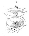
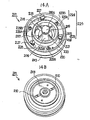
- FIGs. 1 - 3 a high-speed grinder 2 for use in a grinding apparatus 1 according to the present invention.
- the high-speed grinder 2 comprises a pair of rotary disc 3 and stationary disc 4.
- the rotary disc 3 is secured to a rotary shaft 6 connected to a drive means 5 arranged in the grinding apparatus 1, and the stationary disc disposed in the opposite position to the rotary disc 3 is mounted to a hopper 7 for feeding a raw material to be grinded, as shown in Fig. 3.
- the rotary shaft 6 is coaxially arranged to the drive means 5, however, these members may be indirectly connected via a coupling belt or the like, eccentrically.
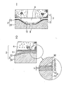
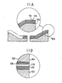
- the rotary disc 3 includes a base 10 and a surface layer 12 thereon, on which a great number of grinding material particles 15 are sticked or embedded partially.
- the rotary disc 3 is formed in a cone-shape having a hollow part 13 so that a strong grinding force may occur at its slant surface by virtue of a centrifugal force while the rotary disc 3 is rotated.
- the grinding material particles 15 which are dispersed closely and aligned regularly, are embedded in the surface layer 12 in the form of at least one layer, preferably 4 - 5 layers, and the grinding material particles 15 of the outermost layer stand close together and project upwards approximately at most 40 micrometers and its height h from the surface of the surface layer 12, thereby forming microbites of an approximately equal height, which constitute a grinding surface 14 of the rotary disc 3, as shown in Fig. 2.
- the grinding material particles 15 of the grinding surface 14 are composed of one or at least two kinds of superhard particles such as diamond and boron nitride, having a knoop hardness of 7000 - 3500 and a height of at most 100 micrometers.
- the particle size of the grinding particles 15 of the grinding surface 14 is relatively coarse in its central portion and relatively thin in its peripheral portion and is gradually diminished from the central portion to the peripheral portion.
- the grinding strength of the grinding surface 14 of the rotary disc 3 is larger than that of the stationary disc 4, and thereby the grinding surface 14 is given a sharp and sufficient grinding strength.
- the formation of the surface layer 12 onto the base 10 can be readily performed by applying a metal plating or at the time when the grinding material particles 15 are sticked onto the base 10 by using a synthetic resin material.
- the grinding surface 14 of the rotary disc 3 not only possesses a sharp grinding strength but also forms a screen like teeth of a comb by standing close together. Hence, the space between the teeth of the grinding particles functions as a fine screen, and therefore the grinded material particles having a size capable of passing through this space can be allowed to be passed therethrough by the centrifugal force caused by the rotation of the rotary disc, to be released outside, with the result of the equalization of the particle size of the grinded particles.
- the coarse particles grinded incapable of passing through the space between the grinding particles still stay inside the grinder and are then fine-grinded in a short time to pass that space.
- the stationary disc 4 includes a grinding surface 24 on its lower side opposite to the grinding surface 14 of the rotary disc 3 and the grinding strength of the grinding surface 24 of the stationary disc 4 is inferior to that of the rotary disc 3.
- the grinding surface 24 of the stationary disc 4 is so formed on its surface layer 22 in the same manner as the surface layer 12 of the rotary disc 3 that a large number of superhard grinding material particles 25 sticked or embedded in the surface layer 22 may project at an approximately equal distance in height from the surface of the surface layer 22, thereby obtaining microbites having an approximately equal height, as shown in Fig. 2.
- the grinding surface 24 of the stationary disc 4 is formed in the same manner as the grinding surface 14 of the rotary disc 3 by aligning a large number of the superhard grinding material particles 25 onto a base 30 and then applying a metal plating or a synthetic resin material onto the base 30 to stick the grinding material particles thereto.
- the grinding material particles 25 of the grinding surface 24 of the stationary disc 4 are made of the same materials as those of the rotary disc 3, that is, the diamond or the boron nitride corresponding to the diamond or the boron nitride used in the grinding surface 14 of the rotary disc 3.
- the particle size of the grinding material particles 25 of the stationary disc 4 is relatively smaller than that of the grinding material particles 15 of the rotary disc 3.
- the rotary disc 3 In order to set up a clearance between the rotary disc 3 and the stationary disc 4, the rotary disc 3 is brought near to the stationary disc 4 gradually and then the rotary disc 3 is lightly contacted with the stationary disc 4. Then, what is called the dressing is conducted between the two discs and hence the clearance between the two discs is stabilized. That is, since the coarse particles of the rotary disc 3 have a relatively strong grinding force and the fine particles of the stationary disc 4 have a relatively inferior grinding force, when the two discs are contacted with each other, the grinding material particles of the rotary disc 3 are not worn away but only the grinding material particles of the stationary disc 4 are grinded unilaterally to be worn away, resulting in that the two discs get to fit each other therebetween.
- the raw material to be grinded is fed in the clearance between the opposite grinding surfaces of the two discs, and, while rotating the rotary disc 3, the material radially moving in the peripheral direction by virture of the centrifugal force is grinded into the fine particles.
- the grinded fine particles are discharged from the periphery of the grinder.
- the raw material is grinded into the fine particles in a room 9 and only the fine particles grinded to the extent of enabling to pass through the gaps between the teeth-like grinding material particles, can be allowed to be passed through the gaps, thereby being discharged outside from the peripheral portions of the discs. Consequently, the gaps between the teeth-like grinding material particles act as a classifying means such as a sieve and a screen.
- a grinding apparatus 1 including the high-speed grinder 2 above-described, a motor 30 for driving the rotary disc 3 through the shaft 5, pulleys 31 and 33 connected to the motor 30 and the shaft 5, respectively, and endless belt 32 extended between the two pulleys 31 and 33, and a discharge chute 34 from which the grinded particle material is discharged.
- the examination is conducted by the light transmission method. 44 - 20 micrometers 17.2% 20 - 10 micrometers 16.5% 10 - 4 micrometers 12.3% 4 - 2 micrometers 11.1% at most 2 micrometers 42.9%
- the clearance between the two discs is measured as follows: Projection of grinding particles 30 - 40 micrometers Deflection of discs' rotation +) 5 - 15 micrometers Clearance of two discs 35 - 55 micrometers
- the specifications are in the followings:
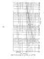
- Fig. 5 is a log-log graph showing a volume percent change of a deposit in a measuring cylinder with the passage of time, which is obtained by a sedimentation test using the obtained grinded material.
- a line M is obtained by using the grinded material which is repeatedly grinded four timed by the high-speed grinder 2 of the apparatus 1
- a line N is obtained by using the material which is grinded only one time by the grinder.
- 2% of the deposit means, in its turn, that the colloidal floating substance and the transparent liquid portion seen in the uppermost portion of the measured cylinder occupy 98%.
- the deposit amount of the material grinded four times is larger than that of the material grinded one time, but its difference is slight. Therefore, it is readily understood that the raw material can be grinded into extremely fine particles even one time grinding by the high-speed grinder according to the present invention and hence this grinder is superior in its grinding capacity.
- the roughly grinded trunk shucks of chickens are grinded in existence of a coolant by using the highspeed grinder 2 in the same manner as above, in which the diameters of the two discs are both 18 cm and the clearance between the two discs is 0.05 mm and in which the particles of the grinding surface are 20 mesh, and the rotating speed of the rotary disc is 1500 - 1800 r.p.m., thereby obtaining a slurry composed of a mixture of meat protein paste and bone powder of at most 10 micrometers, which is dispersed therein.
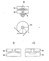
- a rotary disc 53 has a flat grinding surface 64.
- the form of the grinding surface of the stationary disc depends on the nature of the material to be grinded, and in this case in which the grinding surface 64 of the rotary disc 53 is formed flat, a grinding surface 74 of a stationary disc 54 is preferably formed to somewhat concave-form.
- This type grinder can by used for grinding a relatively easily grindable material.
- the grinding material particles are embedded over the entire grinding surface of the rotary disc in the above described embodiments, however, the grinding material particles may be omitted in the central portion of the grinding surface of the rotary disc.
- the grinding surface is formed by embedding the grinding material particles in the surface layer of the stationary disc, however, the whole stationary disc may be formed by a material having a relatively low hardness such as a brown alumina grinding material (A), a white alumina grinding material (WA), a black silundum grinding material (C) and a green silundum grinding material (GC).
- the hardness of the stationary disc is preferably approximate 2/3 of that of the grinding material particles of the rotary disc.
- a pair of rotary disc 83 and stationary disc 84 shown in Fig. 8 are preferably used.
- the material to be grinded is pushed to the stationary disc 84 by virtue of a centrifugal force caused by the high-speed rotation of the rotary disc 83, thereby properly grinding the material.
- FIG. 10 there is shown further embodiment of a pair of rotary disc 93 and stationary disc 94, which may be effectively used as well.
- a plurality of layers of grinding material particles 115 are embedded in a surface layer 112 of a rotary disc 103 so that the outermost layer may constitute the microbites, and a plurality of layers of grinding material particles 125 are embedded in a surface layer 122 of a stationary disc 104 in a similar manner to the rotary disc 103.
- the next outermost layer may be utilized by conducting a truing or a dressing, which is advantageous.
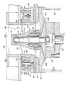
- FIGs. 12 - 14 there is shown still another embodiment of a grinder 201 for use in a grinding apparatus according to the present invention.
- the grinder 201 comprises a rotary shaft 202, a rotary disc 203 coaxially connected to the base portion of the shaft 202, having a grinding surface 203A on its top, and a stationary disc 204 opposite to the grinding surface 203A of the rotary disc 203.
- This grinding surface 203A is formed by electrodepositing diamond fine particles onto the top surface of the rotary disc 203, thereby coating as a diamond electrodeposition layer thereto.
- the stationary disc 204 which is an annular grinder to be contacted with the grinding surface 203A so as to be dressed, is arranged over the rotary disc 203.
- the rotary disc 203 is so connected to the shaft 202 that the axis of the shaft 202 may be perpendicular to the grinding surface 203A of the rotary disc 203 in order to remove a deflection of the grinding surface 203A while rotating the rotary disc 203.
- the bearing holder 205 On the free top end portion of the shaft 202 is fitted a bearing holder 205 holding a couple of ball bearings 211 and 212 and a needle bearing 215 in its lower and upper inner parts for supporting the shaft 202.
- the bearing holder 205 comprises a dome-formed bearing holding portion 206, four arms 207 radially extending from the bearing holding portion 206, and a tubular portion 208 connected to the bearing holding portion 206 via the four arms 207. Between the adjacent arms 207 of the bearing holder 205 there are opening spaces as passages 208A through which the grinded materials may pass.
- the tubular portion 208 of the bearing holder 205 is provided with a threaded portion in its upper outer periphery, which a threaded portion formed in an upper inner periphery of a ring 220 hereinafter described in detail is engaged with.
- the top of the bearing holding portion 206 of the bearing holder 205 is covered by a cap 209 fitted thereon.
- An annular housing 230 is arranged over the rotary disc 203, and the housing 230 holds the stationary disc 204 on its bottom through an annular holding disc 235 mounted to the bottom of the housing 230.
- the housing 230 is also provided with a hollow portion 231 for receiving the ring 220 and has a circular opening 232 in its central portion so that the tubular portion 208 of the bearing holder 205 may pass through the openings of the stationary disc 204, the annular holding disc 235 and the annular housing 230, as shown in Fig. 13.
- the ring 220 for supporting the housing 230 hanging thereon is contained in the hollow portion 231 of the housing 230.
- the ring 220 is engaged with the outer periphery of the tubular portion 208 of the bearing holder 205, and thereby the ring 220 is integrally connected to the bearing holder 205.
- the ring 220 is provided with an annular groove 223 _n its top portion, in which an annular rubber packing 237 is inserted.
- the ring 220 is also provided with a mechanism 224 for adjusting a clearance between the grinding surface 203A of the rotary disc 203 and the stationary disc 204.
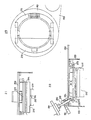
- the clearance adjusting mechanism 224 comprises hanging-support means 225 for supporting the housing 230 hanging thereon and biasing the housing towards the ring 220, and push means 226 for pushing the annular housing 230 retaining the stationary disc 204 towards the rotary disc 203 against the biasing force of the hanging-support means 225.
- three hanging-support means 225 and three push means 226 are alternately arranged at an equal interval.
- the hanging-support means 225 comprises a guide pin 227 having a male screw in its lower end, which passes through an opening 222 formed in the hollow portion 221 of the ring 220 and the male screw or which is engaged with a female screw formed in the housing 230, and a compressed coil spring 228 rounded around the guide pin 227, which biases the housing 230 towards the ring 220.
- the housing 230 is supported by the hanging-support means 225 hanging thereon by approximately equal forces thereof.
- the push means 226 comprises a nut member 229A secured to the ring 220 coaxially with another opening formed approximately between the two openings 222 of the ring 220, and a screwed push pin 229B which is engaged with the nut member 229A so that the push pin 229B may pass downwards through the another opening of the ring 220 so as to push the housing 230 towards the rotary disc 203. Therefore, the stationary disc 204 mounted to the bottom of the housing 230 through the holding disc 235 may be pushed towards the rotary disc 203 by the push means 226 against the biasing forces of the hanging-support means 225.
- the stationary disc 204 mounted to the housing 230 is pushed down towards the rotary disc 203 in order to able to supplementarily adjust the clearance between the rotary disc 203 and the stationary disc 204, which is widened by the wear and tear.
- a grinding apparatus 251 including the grinder 201 formed in a cassette type, described above.
- the apparatus 251 comprises a mounting base 252 installed on a floor F , a housing 253 secured onto the base 252, a rotary shaft 254 arranged upright within the housing 253, a cover 263 for covering the free end face of the housing 253, and the cassette type of the grinder 201 received in the housing 253.
- the shaft 254 is driven by a driving motor 255 arranged outside the housing 253, and the rotation of the shaft 254 is transmitted to the rotary disc 203 of the grinder 201, thereby performing the grinding the material.
- the shaft 254 is connected via pulleys 257 and 258 mounted to a motor shaft 256 of the motor 255 and the shaft 254, respectively, and a V-shaped belt 259 extended between the two pulleys 257 and 258, to the motor 255.
- a pair of leg bodies 262 are secured to the base 252 outside of the cover 261, as clearly shown in Fig. 16.
- a cylindrical body 265 for guiding a support pillar 264 when the cover body 263 is moved up and down, is secured to the leg body 262, and the two pillars 264 are coupled by a connecting plate 266.
- the base portion of the cover body 263 is pivotally mounted to the center of the connecting plate 266 so as to be pivoted in the horizontal plane, as shown in Fig. 17.
- the connecting plate 266 is moved up and down by a jack 292 via a rod thereof, the pillars 264 are simultaneously moved up and down, and, when the cover body 263 is pivoted in the horizontal plane apart from the grinder 201, the upper side of the apparatus 251 is released to the atmosphere.
- a cylinder 268 is disposed for holding bearings 271 and 272 for supporting the shaft 254 on its upper and lower portions, and for surrounding the shaft 254.
- a coupling 269 connected to the shaft 254, and a clutch 270 having key ways 274 in its upper surface, which connected to the coupling 269 are arranged.
- a pair of keys 210 mounted to the bottom of the rotary disc 203 are engaged with the key ways 274 of the clutch 270, as shown in Fig. 21, to mount the cassette type of the grinder 201 onto the clutch 270, resulting in that the rotation of the shaft 254 may be transmitted to the rotary disc 203. Further, as shown in Figs.
- a frame member 273 for stopping the upward movement of the grinder 201 is pivotally mounted to the inner upper end of the housing 253 so that the frame member 273 may pivot in the horizontal plane to engage with the cutouts 234 of the annular housing 230 of the grinder 201.
- a conduit 275 for discharging the water dropping from water weep holes 203B provided in the lower side of the rotary disc 203 is disposed outside the clutch 270, as shown in Fig. 17.
- the cover body 263 is provided with an inlet 263A in its about central portion, and the lower outlet 267A of a hopper 267 is positioned right over the inlet 263A of the cover body 263.
- the hopper 267 is moved up and down along with the cover body 263 by means of the jack 292.
- a fine adjusting means 280 for adjusting the clearance between the rotary disc 203 and the stationary disc 204 is disposed to the cover body 263, as shown in Fig. 22.
- the front end of the fine adjusting means 280 abuts on the frame member 273 engaged with the cutouts 234 of the housing 230 of the grinder 201.
- the fine adjusting means 280 comprises a fine adjusting screw rod 282 having a handle 281 in its one end which is engaged with a female screw part 283 fixed to the cover body 263, and an abut portion 284 mounted to the other end of the screw rod 282, which abuts on the frame member 273.
- the female screw part 283 possesses a stop screw 285 for stopping the screw rod 282 in the desired set condition.
- a fork member 289 is mounted to the front end of a base plate 288 secured to the cover body 263.
- a screw rod 290 for fixing the cover body 263 to the cover 261 is pivotally mounted to the outer upper end portion of the cover 261.
- the screw rod 290 is pivoted upwards into the concave portion of the fork member 289, and a clamping screw 293 engaged on the screw rod 290 is tightened, thereby fixing the cover body 263 onto the cover 261.
- the rubber packing 237 fitted in the groove 223 of the ring 220 of the grinder 201 is pressed in contact with the lower surface of the cover body 263, and hence the engagement of the key ways 274 of the clutch 270 with the keys 210 of the rotary disc 203 is more ensured.
- the stationary disc 204 is pushed down towards the rotary disc 203 by rotating the push pins 229B, to adjust the clearance between the rotary disc 203 and the stationary disc 204, in advance.
- the clearance adjusted grinder 203 of the cassette type is set to the grinding apparatus 251.
- the material to be grinded is fed to the hopper 267 from its inlet 267A, and the material then drops onto the rotary disc 203 rotating within the housing 253 through the inlet 263A of the cover body 263.
- the material is radially moved outwards on the grinding surface 203A of the diamond electrodeposition layer, formed over the rotary disc 203 and is finally grinded into the fine particles between the grinding surface 203A of the rotary disc 203 and the stationary disc 204, and thereby the grinded fine particles are scattered outwards from the periphery of the discs.
- the scattered particles are stuck against the inner wall of the cover 261 and are then discharged outside from the discharge chute 260.
- the waste water is discharged outside passing through the water weep holes 203B of the rotary disc 203 and then the conduit 275.
- the stop screw 285 is loosed and the handle 281 of the fine adjusting means 280 is rotated so as to push down the frame member 273, resulting in that the housing 230 of the grinder 201 is pushed down against the biasing forces of the coil springs 228 of the hanging-support means 225. Accordingly, the widened clearance between the rotary disc 203 and the stationary disc 204 is readily adjusted to be narrowed.
- the cassette type of the grinder 201 will be replaced by new one in the apparatus 251 as follows. That is, the clampling screw 293 positioned in the front end of the cover body 263 is loosed and the screw rod 290 is released from the fork member 289. Then, the cover body 263 along with the hopper 267 are lifted by actuating the jack 292, and thereafter the cover body 263 and the hopper 267 are pivoted sideways in the horizontal plane, with the result of releasing of the top end of the housing 253 in the apparatus 251. Further, the frame member 273 is pushed up. Now, the cassette type of the grinder 201 may readily be removed from the clutch 270, and a new grinder 201 is set up to the clutch 270. Then, the operation is conducted in the reverse order to the aforementioned operation to be ready to start the grinding.
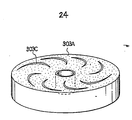
- a rotary disc having a different grinding surface from that of the rotary disc 203 aforementioned.
- a plurality of spiral grooves 303C are formed on a grinding surface 303A.
- a plurality of radial grooves may be formed on the grinding surface of the rotary disc.
- the grinded particles are discharged outside through screens formed by the grinding material particles of the rotary disc, the oversized grinded particles are hardly resulted in and the desired particle sized of the fine grinded particles are readily obtained. Further, the clearance between the rotary disc and the stationary disc can be maintained stably and thus the cause of the over grinding can be effectively prevented.
- the obtained particles are not mashed and hence the product particles are formed in the regular form as well as the cutting surfaces of the particles are smooth. Consequently, the load during the gridning operation is light and the working efficiency per unit time is very high.
- the grinding material of the discs is superhard and thus the wear and tear of the discs is less, less powder of the grinding material admixes the grinded material, and the high purity of the grinded material can be readily obtained.
- the heat generated in the tips of the microbites is effectively transmitted or spreaded outside as well as cooled by a coolant and hence the grinded material may not affected by the heat at all.
- the wear and tear of the grinding surfaces of the discs is quite small to obtain long lives of the discs, and accordingly the frequencys of the clearance adjustements and the replacement of the discs as well as the repair and correction of the forms of the discs are largely improved, with the result of high operational efficacy.
- the grinder when the clearance between the rotary and the stationary discs are widened and the clearance adjustment comes near critical, the grinder can be readily and quickly replaced by new one, thereby promoting the operational efficiency of the grinding.
- the rotary disc is secured to the rotary shaft of a short length perpendicular to the axis of the shaft, the deflection of the grinding surface of the rotary disc rotating is effectively removed.
- the particle size of the grinding particles can be within the predetermined rang exactly.
- the assembling and the sisassembling of the grinder and the cleanup of the grinder can be carried out readily and quickly.
Landscapes
- Engineering & Computer Science (AREA)
- Food Science & Technology (AREA)
- Polishing Bodies And Polishing Tools (AREA)
- Crushing And Grinding (AREA)
Applications Claiming Priority (4)
| Application Number | Priority Date | Filing Date | Title |
|---|---|---|---|
| JP29860985A JPS62155945A (ja) | 1985-12-28 | 1985-12-28 | 微粉砕機における高速グラインダ |
| JP298609/85 | 1985-12-28 | ||
| JP7998286A JPS62237952A (ja) | 1986-04-09 | 1986-04-09 | 微粉砕機の粉砕手段 |
| JP79982/86 | 1986-04-09 |
Publications (3)
| Publication Number | Publication Date |
|---|---|
| EP0227879A2 true EP0227879A2 (fr) | 1987-07-08 |
| EP0227879A3 EP0227879A3 (en) | 1988-08-03 |
| EP0227879B1 EP0227879B1 (fr) | 1991-08-14 |
Family
ID=26420961
Family Applications (1)
| Application Number | Title | Priority Date | Filing Date |
|---|---|---|---|
| EP86107602A Expired EP0227879B1 (fr) | 1985-12-28 | 1986-06-04 | Broyeur utilisé dans un appareil broyeur |
Country Status (3)
| Country | Link |
|---|---|
| US (1) | US4767070A (fr) |
| EP (1) | EP0227879B1 (fr) |
| DE (1) | DE3680891D1 (fr) |
Cited By (4)
| Publication number | Priority date | Publication date | Assignee | Title |
|---|---|---|---|---|
| EP0480851A1 (fr) * | 1990-10-11 | 1992-04-15 | Technogenia S.A. | Plaque à surface antiabrasion, et procédé pour sa réalisation |
| GB2294213A (en) * | 1994-10-12 | 1996-04-24 | Nipponkoatsudenki Kabushikikai | Conical mill |
| EP1002583A3 (fr) * | 1998-11-17 | 2000-11-29 | H.-I. Pallmann GmbH & Co. | Ajustage de stator pour machine de traitement de matériau |
| CN106799282A (zh) * | 2017-01-11 | 2017-06-06 | 南昌浩牛科技有限公司 | 一种石膏精细研磨装置 |
Families Citing this family (8)
| Publication number | Priority date | Publication date | Assignee | Title |
|---|---|---|---|---|
| US4951888A (en) * | 1989-08-24 | 1990-08-28 | Sprout-Bauer, Inc. | Refining element and method of manufacturing same |
| US5076504A (en) * | 1990-05-31 | 1991-12-31 | Animal Health Sales | Poultry pulverizer |
| US6368199B1 (en) * | 1995-12-08 | 2002-04-09 | Saint-Gobain Technology Company | Backing plates for abrasive disks |
| US6394372B2 (en) * | 1999-01-20 | 2002-05-28 | James C. Rine | Refining disk |
| CN102755918B (zh) * | 2012-08-03 | 2014-07-09 | 贵阳探矿机械厂 | 一种圆盘粉碎机 |
| CN103418458B (zh) * | 2013-08-09 | 2015-08-05 | 国家电网公司 | 发电厂垢和腐蚀产物分析试样的自动制备装置 |
| CN104148142B (zh) * | 2014-08-06 | 2017-01-18 | 袁华庆 | 纳米泥浆制作方法 |
| CN117563744B (zh) * | 2024-01-15 | 2024-04-16 | 大庆辰平钻井技术服务有限公司 | 一种错断井报废封堵的封堵剂研磨设备 |
Family Cites Families (7)
| Publication number | Priority date | Publication date | Assignee | Title |
|---|---|---|---|---|
| GB336828A (fr) * | 1900-01-01 | |||
| US2120697A (en) * | 1935-08-05 | 1938-06-14 | Carborundum Co | Apparatus for disintegrating fibrous substances |
| CH369953A (de) * | 1959-04-01 | 1963-06-15 | Forsch Inst Professor Ing Chem | Maschine zum Feinvermahlen von Stoffen |
| DE1757244C3 (de) * | 1968-04-13 | 1975-01-02 | Johann Georg Dr.Med. Dent. 7742 St. Georgen Schnitzer | Verfahren zur Herstellung von Mahlsteinen |
| US3746266A (en) * | 1971-10-01 | 1973-07-17 | Gen Signal Corp | Waste disintegrator rotor and ring assembly |
| US4597536A (en) * | 1981-10-29 | 1986-07-01 | The Goodyear Tire & Rubber Company | Comminuting apparatus with improved rotor and stator composition |
| EP0122402A3 (fr) * | 1983-02-23 | 1986-11-12 | Heinrich Gerk | Concasseur de grains |
-
1986
- 1986-06-04 EP EP86107602A patent/EP0227879B1/fr not_active Expired
- 1986-06-04 DE DE8686107602T patent/DE3680891D1/de not_active Expired - Lifetime
- 1986-06-06 US US06/871,311 patent/US4767070A/en not_active Expired - Fee Related
Cited By (8)
| Publication number | Priority date | Publication date | Assignee | Title |
|---|---|---|---|---|
| EP0480851A1 (fr) * | 1990-10-11 | 1992-04-15 | Technogenia S.A. | Plaque à surface antiabrasion, et procédé pour sa réalisation |
| FR2667804A1 (fr) * | 1990-10-11 | 1992-04-17 | Technogenia Sa | Plaque a surface antiabrasion, et procede pour sa realisation. |
| US5201917A (en) * | 1990-10-11 | 1993-04-13 | Technogenia S.A. | Plate with an abrasion-proof surface and process for the production thereof |
| AU646297B2 (en) * | 1990-10-11 | 1994-02-17 | Technogenia S.A. | Plate with an abrasion-proof surface and process for the production thereof |
| GB2294213A (en) * | 1994-10-12 | 1996-04-24 | Nipponkoatsudenki Kabushikikai | Conical mill |
| GB2294213B (en) * | 1994-10-12 | 1998-06-24 | Nipponkoatsudenki Kabushikikai | Pulverizer |
| EP1002583A3 (fr) * | 1998-11-17 | 2000-11-29 | H.-I. Pallmann GmbH & Co. | Ajustage de stator pour machine de traitement de matériau |
| CN106799282A (zh) * | 2017-01-11 | 2017-06-06 | 南昌浩牛科技有限公司 | 一种石膏精细研磨装置 |
Also Published As
| Publication number | Publication date |
|---|---|
| EP0227879B1 (fr) | 1991-08-14 |
| US4767070A (en) | 1988-08-30 |
| DE3680891D1 (de) | 1991-09-19 |
| EP0227879A3 (en) | 1988-08-03 |
Similar Documents
| Publication | Publication Date | Title |
|---|---|---|
| EP0227879A2 (fr) | Broyeur utilisé dans un appareil broyeur | |
| EP0238432A2 (fr) | Méthode et dispositif de broyage à haut rendement | |
| CN115846020A (zh) | 一种球形石墨生产用研磨设备 | |
| CN115007270A (zh) | 一种生石灰加工用的磨粉加工系统及加工方法 | |
| CN114798080A (zh) | 一种豆制品磨浆设备 | |
| CN1184713A (zh) | 用于细化和再研磨的圆锥回转破碎碾磨机 | |
| CN112156865B (zh) | 一种沥青改性剂制备工艺 | |
| CN118751338B (zh) | 一种多孔陶瓷生产用陶瓷粉末研磨设备 | |
| CA1144127A (fr) | Dispositif et methode de broyage d'un materiau | |
| CN112246396A (zh) | 一种减震式可移动的中药磨削机 | |
| CN116747952A (zh) | 一种植物蛋白提取用研磨装置 | |
| CA2594272C (fr) | Plaque d'appui pour bol d'un touret a meuler | |
| AU715704B2 (en) | Milling and pulverising apparatus and method | |
| CN113245043B (zh) | 中草药粉碎机 | |
| US5076506A (en) | Separator for separating processed material from grinding medium | |
| SU884721A1 (ru) | Шарокольцева мельница | |
| US4204949A (en) | Device for wet classification of a mixture of solid components according to size | |
| CN221536858U (zh) | 一种研磨材料研磨成粉装置 | |
| SU1627246A1 (ru) | Устройство дл измельчени сыпучих материалов | |
| CN218905967U (zh) | 一种酚醛树脂摩擦材料研磨机 | |
| CN220879054U (zh) | 一种辣椒酱生产用磨浆装置 | |
| SU1479139A1 (ru) | Устройство дл сортировки щепы | |
| CN217397591U (zh) | 一种金刚石微粉拉曼检测圆盘自动装料装置 | |
| CN117299293B (zh) | 一种多研磨面的立式研磨机 | |
| JPH0239940B2 (fr) |
Legal Events
| Date | Code | Title | Description |
|---|---|---|---|
| PUAI | Public reference made under article 153(3) epc to a published international application that has entered the european phase |
Free format text: ORIGINAL CODE: 0009012 |
|
| AK | Designated contracting states |
Kind code of ref document: A2 Designated state(s): BE CH DE FR GB IT LI NL |
|
| PUAL | Search report despatched |
Free format text: ORIGINAL CODE: 0009013 |
|
| AK | Designated contracting states |
Kind code of ref document: A3 Designated state(s): BE CH DE FR GB IT LI NL |
|
| 17P | Request for examination filed |
Effective date: 19890112 |
|
| 17Q | First examination report despatched |
Effective date: 19890612 |
|
| GRAA | (expected) grant |
Free format text: ORIGINAL CODE: 0009210 |
|
| DIN1 | Information on inventor provided before grant (deleted) | ||
| RAP1 | Party data changed (applicant data changed or rights of an application transferred) |
Owner name: NAGAO, MASAMICHI Owner name: HITACHI TECHNO ENGINEERING CO., LTD. Owner name: NAGAO, MASAAKI |
|
| AK | Designated contracting states |
Kind code of ref document: B1 Designated state(s): BE CH DE FR GB IT LI NL |
|
| PG25 | Lapsed in a contracting state [announced via postgrant information from national office to epo] |
Ref country code: BE Effective date: 19910814 Ref country code: CH Effective date: 19910814 Ref country code: NL Effective date: 19910814 Ref country code: LI Effective date: 19910814 Ref country code: IT Free format text: LAPSE BECAUSE OF FAILURE TO SUBMIT A TRANSLATION OF THE DESCRIPTION OR TO PAY THE FEE WITHIN THE PRE;WARNING: LAPSES OF ITALIAN PATENTS WITH EFFECTIVE DATE BEFORE 2007 MAY HAVE OCCURRED AT ANY TIME BEFORE 2007. THE CORRECT EFFECTIVE DATE MAY BE DIFFERENT FROM THE ONE RECORDED.SCRIBED TIME-LIMIT Effective date: 19910814 |
|
| REF | Corresponds to: |
Ref document number: 3680891 Country of ref document: DE Date of ref document: 19910919 |
|
| REG | Reference to a national code |
Ref country code: CH Ref legal event code: PL |
|
| ET | Fr: translation filed | ||
| NLV1 | Nl: lapsed or annulled due to failure to fulfill the requirements of art. 29p and 29m of the patents act | ||
| PLBE | No opposition filed within time limit |
Free format text: ORIGINAL CODE: 0009261 |
|
| STAA | Information on the status of an ep patent application or granted ep patent |
Free format text: STATUS: NO OPPOSITION FILED WITHIN TIME LIMIT |
|
| 26N | No opposition filed | ||
| PGFP | Annual fee paid to national office [announced via postgrant information from national office to epo] |
Ref country code: GB Payment date: 19950615 Year of fee payment: 10 |
|
| PGFP | Annual fee paid to national office [announced via postgrant information from national office to epo] |
Ref country code: FR Payment date: 19950619 Year of fee payment: 10 |
|
| PGFP | Annual fee paid to national office [announced via postgrant information from national office to epo] |
Ref country code: DE Payment date: 19950727 Year of fee payment: 10 |
|
| PG25 | Lapsed in a contracting state [announced via postgrant information from national office to epo] |
Ref country code: GB Effective date: 19960604 |
|
| GBPC | Gb: european patent ceased through non-payment of renewal fee |
Effective date: 19960604 |
|
| PG25 | Lapsed in a contracting state [announced via postgrant information from national office to epo] |
Ref country code: FR Effective date: 19970228 |
|
| PG25 | Lapsed in a contracting state [announced via postgrant information from national office to epo] |
Ref country code: DE Effective date: 19970301 |
|
| REG | Reference to a national code |
Ref country code: FR Ref legal event code: ST |