EP0227985A2 - Sonde ultrasonique - Google Patents
Sonde ultrasonique Download PDFInfo
- Publication number
- EP0227985A2 EP0227985A2 EP86117065A EP86117065A EP0227985A2 EP 0227985 A2 EP0227985 A2 EP 0227985A2 EP 86117065 A EP86117065 A EP 86117065A EP 86117065 A EP86117065 A EP 86117065A EP 0227985 A2 EP0227985 A2 EP 0227985A2
- Authority
- EP
- European Patent Office
- Prior art keywords
- electrodes
- polymer film
- ultrasonic sensor
- sensor according
- membrane
- Prior art date
- Legal status (The legal status is an assumption and is not a legal conclusion. Google has not performed a legal analysis and makes no representation as to the accuracy of the status listed.)
- Granted
Links
- 229920006254 polymer film Polymers 0.000 claims abstract description 56
- 239000012528 membrane Substances 0.000 claims description 24
- 239000007788 liquid Substances 0.000 claims description 11
- 239000002184 metal Substances 0.000 claims description 4
- 229910052751 metal Inorganic materials 0.000 claims description 4
- 230000010287 polarization Effects 0.000 claims description 4
- 239000003792 electrolyte Substances 0.000 claims description 3
- 238000000034 method Methods 0.000 claims description 3
- 230000005684 electric field Effects 0.000 claims 1
- 238000004519 manufacturing process Methods 0.000 claims 1
- 238000002604 ultrasonography Methods 0.000 abstract description 23
- 230000035939 shock Effects 0.000 abstract description 10
- 230000008878 coupling Effects 0.000 description 10
- 238000010168 coupling process Methods 0.000 description 10
- 238000005859 coupling reaction Methods 0.000 description 10
- XLYOFNOQVPJJNP-UHFFFAOYSA-N water Substances O XLYOFNOQVPJJNP-UHFFFAOYSA-N 0.000 description 9
- 239000002033 PVDF binder Substances 0.000 description 7
- 239000004020 conductor Substances 0.000 description 7
- BASFCYQUMIYNBI-UHFFFAOYSA-N platinum Chemical compound [Pt] BASFCYQUMIYNBI-UHFFFAOYSA-N 0.000 description 7
- 229920002981 polyvinylidene fluoride Polymers 0.000 description 7
- 229910001220 stainless steel Inorganic materials 0.000 description 6
- 239000010935 stainless steel Substances 0.000 description 6
- 238000005259 measurement Methods 0.000 description 5
- 230000006378 damage Effects 0.000 description 3
- 239000000463 material Substances 0.000 description 3
- 230000003071 parasitic effect Effects 0.000 description 3
- 239000004793 Polystyrene Substances 0.000 description 2
- 239000000853 adhesive Substances 0.000 description 2
- 230000001070 adhesive effect Effects 0.000 description 2
- 239000011888 foil Substances 0.000 description 2
- 239000010931 gold Substances 0.000 description 2
- 239000007769 metal material Substances 0.000 description 2
- 239000004033 plastic Substances 0.000 description 2
- 229920003023 plastic Polymers 0.000 description 2
- 229910052697 platinum Inorganic materials 0.000 description 2
- 229920000642 polymer Polymers 0.000 description 2
- 239000011116 polymethylpentene Substances 0.000 description 2
- 229920000306 polymethylpentene Polymers 0.000 description 2
- 229920002620 polyvinyl fluoride Polymers 0.000 description 2
- MIZLGWKEZAPEFJ-UHFFFAOYSA-N 1,1,2-trifluoroethene Chemical group FC=C(F)F MIZLGWKEZAPEFJ-UHFFFAOYSA-N 0.000 description 1
- 229910001369 Brass Inorganic materials 0.000 description 1
- 208000000913 Kidney Calculi Diseases 0.000 description 1
- 206010029148 Nephrolithiasis Diseases 0.000 description 1
- 229920002845 Poly(methacrylic acid) Polymers 0.000 description 1
- FAPWRFPIFSIZLT-UHFFFAOYSA-M Sodium chloride Chemical compound [Na+].[Cl-] FAPWRFPIFSIZLT-UHFFFAOYSA-M 0.000 description 1
- 239000010951 brass Substances 0.000 description 1
- 229920001940 conductive polymer Polymers 0.000 description 1
- 229920001577 copolymer Polymers 0.000 description 1
- 238000013461 design Methods 0.000 description 1
- 238000011161 development Methods 0.000 description 1
- 230000000694 effects Effects 0.000 description 1
- XUCNUKMRBVNAPB-UHFFFAOYSA-N fluoroethene Chemical compound FC=C XUCNUKMRBVNAPB-UHFFFAOYSA-N 0.000 description 1
- PCHJSUWPFVWCPO-UHFFFAOYSA-N gold Chemical compound [Au] PCHJSUWPFVWCPO-UHFFFAOYSA-N 0.000 description 1
- 229910052737 gold Inorganic materials 0.000 description 1
- 210000003734 kidney Anatomy 0.000 description 1
- 239000010410 layer Substances 0.000 description 1
- 150000004702 methyl esters Chemical class 0.000 description 1
- 238000012544 monitoring process Methods 0.000 description 1
- 229910000510 noble metal Inorganic materials 0.000 description 1
- 229920003229 poly(methyl methacrylate) Polymers 0.000 description 1
- 239000004926 polymethyl methacrylate Substances 0.000 description 1
- 229920002223 polystyrene Polymers 0.000 description 1
- 238000012545 processing Methods 0.000 description 1
- 239000011241 protective layer Substances 0.000 description 1
- 229920006126 semicrystalline polymer Polymers 0.000 description 1
- 230000035945 sensitivity Effects 0.000 description 1
- BFKJFAAPBSQJPD-UHFFFAOYSA-N tetrafluoroethene Chemical group FC(F)=C(F)F BFKJFAAPBSQJPD-UHFFFAOYSA-N 0.000 description 1
Images

Classifications
-
- B—PERFORMING OPERATIONS; TRANSPORTING
- B06—GENERATING OR TRANSMITTING MECHANICAL VIBRATIONS IN GENERAL
- B06B—METHODS OR APPARATUS FOR GENERATING OR TRANSMITTING MECHANICAL VIBRATIONS OF INFRASONIC, SONIC, OR ULTRASONIC FREQUENCY, e.g. FOR PERFORMING MECHANICAL WORK IN GENERAL
- B06B1/00—Methods or apparatus for generating mechanical vibrations of infrasonic, sonic, or ultrasonic frequency
- B06B1/02—Methods or apparatus for generating mechanical vibrations of infrasonic, sonic, or ultrasonic frequency making use of electrical energy
- B06B1/06—Methods or apparatus for generating mechanical vibrations of infrasonic, sonic, or ultrasonic frequency making use of electrical energy operating with piezoelectric effect or with electrostriction
- B06B1/0688—Methods or apparatus for generating mechanical vibrations of infrasonic, sonic, or ultrasonic frequency making use of electrical energy operating with piezoelectric effect or with electrostriction with foil-type piezoelectric elements, e.g. PVDF
-
- Y—GENERAL TAGGING OF NEW TECHNOLOGICAL DEVELOPMENTS; GENERAL TAGGING OF CROSS-SECTIONAL TECHNOLOGIES SPANNING OVER SEVERAL SECTIONS OF THE IPC; TECHNICAL SUBJECTS COVERED BY FORMER USPC CROSS-REFERENCE ART COLLECTIONS [XRACs] AND DIGESTS
- Y10—TECHNICAL SUBJECTS COVERED BY FORMER USPC
- Y10S—TECHNICAL SUBJECTS COVERED BY FORMER USPC CROSS-REFERENCE ART COLLECTIONS [XRACs] AND DIGESTS
- Y10S310/00—Electrical generator or motor structure
- Y10S310/80—Piezoelectric polymers, e.g. PVDF
Definitions
- the invention relates to an ultrasound sensor with a polymer film attached to a support body at least in its edge region, which is piezoelectrically activated at least in a partial region, which is electrically coupled to electrodes.
- So-called miniature or membrane hydrophones are used to determine the properties of an ultrasound field prevailing in a sound-carrying medium, for example water.
- the three-dimensional distribution of the sound pressure amplitude of the ultrasound field is determined by measuring the sound pressure prevailing at different locations in a measuring trough with such a hydrophone.
- a miniature hydrophone in which a piezoactive film made of polyvinylidene fluoride PVDF with electrodes on both of its flat sides and with a thickness of 25 ⁇ m is stretched onto the end face of a stainless steel tube in an electrically insulated manner.
- the diameter of the film is about 1 mm.
- a platinum wire is attached to the inside of the film and is connected to the inner conductor of a coaxial cable. This platinum wire is supported by a backing that fills the interior of the stainless steel tube.
- the outside of the film is electrical with the stainless steel tube contacted and connected to the shield of the coaxial cable.
- a major advantage of such hydrophones is that the acoustic impedance of their piezoelectric elements is better matched to the acoustic impedance of water than would be the case if a piezoceramic material were used. Compared to piezoceramic sensors, this results in both an increased frequency bandwidth and a reduced disruptive influence on the ultrasound field at the measurement location.
- the invention is therefore based on the object of specifying an ultrasonic sensor whose piezoelectric element consists of a polymer and which can also be used when measuring high-energy ultrasonic shock waves.
- the surface charge vibrations in the piezoelectrically active area of the polymer film caused by an ultrasonic wave are electrically coupled via the medium surrounding the polymer film to the electrodes arranged outside the surface area of the polymer film assigned to the piezoelectrically active area of the polymer film .
- the piezoelectrically active central area of the polymer film can thus be arranged in the focus area of a focused ultrasound shock wave, since there is no mechanically unstable electrically conductive layer in the sensitive area of the polymer film.
- the invention is based in part on the knowledge that by using a piezoelectric polymer with a piezoceramic material relatively low dielectric constant, a purely capacitive coupling without high signal losses is possible. Accordingly, the electrodes can be attached spatially separated from the piezoelectrically active region of the polymer film both on the film itself and outside of the film, for example on the support body.
- the electrodes are advantageously designed in such a way that their mutual capacitance is as small as possible compared to the coupling capacitances, in order to reduce the signal losses occurring due to parasitic capacitances.
- One of the electrodes is connected to the electrical ground of the system.
- the coupling capacities to the electrodes are as large as possible. Since, as a rule, the environment of the ultrasound sensor is approximately at ground potential during the measurement, the coupling capacitance of the piezoelectrically active region in particular can be increased by suitable design measures without additional signal-reducing parasitic capacitances occurring.
- a flat, also membrane-like additional ground electrode can be arranged in the ultrasonic sensor opposite the piezoelectrically active region of the membrane parallel to its surface. As a result, the piezoelectrically active region is particularly effectively capacitively coupled to ground.
- cover plates are arranged on the free end faces of the support body opposite the two flat sides of the membrane.
- a tight chamber is created between the cover plate and the membrane, containing a sound-carrying liquid is filled.
- the polarization of the polymer film takes place in an advantageous manner in that it is clamped between movably arranged electrodes located opposite one another and connected to a high voltage.
- the geometrical shape of the end face of these electrodes thus determines the geometrical shape of the piezoelectrically active region of the polymer film.
- electrodes for polarization the end faces of which are provided with an electrically conductive, elastic stamp.
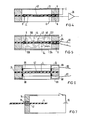
- an ultrasound sensor 2 contains a polymer film 4, for example in the form of a circular disk, which is clamped tightly between two, for example, annular support bodies 6 and forms a membrane 40.
- the polymer film consists of a semicrystalline polymer, for example polyvinyl fluoride PVF or a copolymer of vinyl fluoride with tetrafluoroethylene or trifluoroethylene, in particular biaxially stretched polyvinylidene fluoride PVDF.
- the polymer film 4 is polarized in a central region 42 and is piezoelectrically active.
- the piezoelectrically active area 42 is surrounded by a piezoelectrically inactive area 44.
- the diameter d of the central region 42 is very much smaller than the diameter D of the membrane 40 of the polymer film 4.
- the diameter d of the polarized central region Area 42 smaller than 2 mm, in particular smaller than 1 mm.
- the diameter D of the membrane 40 is advantageously greater than 30 mm, in particular greater than 50 mm choose to reduce the influence of the support body 6 on the sound field to be measured in the central area 42.
- the thickness of the polymer film 4 is between 10 ⁇ m and 100 ⁇ m, in particular between 25 ⁇ m and 50 ⁇ m.
- the polymer film 4 is provided on the surface of its piezoelectrically inactive region 44 on its two flat sides with one electrode 8 each.
- the electrodes 8 are thus arranged in such a way that they are spatially separated from the piezoelectrically active region 42 and do not touch it.
- the electrodes 8 are preferably located in an outer edge region of the polymer film 4, the width of which is less than 1/4, in particular less than 1/10, of the diameter of the film.
- the electrodes 8 have an annular shape, for example, and are arranged, for example, concentrically around the central axis 22 in the region of the membrane 40.
- the electrodes 8 are provided with electrical connection conductors 82, which lead, for example, in radial grooves 62 of the support body 6 to the cylindrical outer edge of the ultrasonic sensor 2.
- the connecting conductors 82 can be connected, for example, with a coaxial cable, which forwards the electrical signals to further processing electronics, for example a charge-sensitive amplifier.
- one of the two connection conductors 82 is connected to the electrical ground.
- the properties of the ultrasound field of an ultrasound transmitter used for medical purposes are generally measured in a basin filled with a sound-carrying liquid, for example water.
- the ultrasonic sensor 2 is thus surrounded by water 10 during the measurement.
- the pressure acting on the polymer film 4 through the ultrasonic field Forces generate 42 high-frequency surface charge vibrations in the piezoelectrically active central region.
- the signal-receiving electrodes 8 are arranged on the outer edge of the membrane area of the polymer film 4, very high sound pressure amplitudes can be measured reproducibly in the central area 40 without the risk of mechanical destruction and the electrodes 8 flaking off the polymer film 4.
- the electrodes 8 can also extend into the area of the polymer film 4 which is clamped between the support bodies 6.
- the grooves 64 in which the connecting conductors 82 run no longer have to extend to the inner edge of the support body 6.
- the two flat sides of the polymer film 4 are each provided with an approximately semi-ring-shaped electrode 86 or 87.
- the two electrodes 86 and 87 are arranged such that they do not overlap.
- the parasitic capacitance which occurs between the electrodes 86 and 87 and which causes a reduction in the electrical useful signal is thereby reduced. This is particularly advantageous if the ultrasound sensor is also to be used for measuring ultrasound fields that are used in medical diagnostics.
- one of the two support bodies 6 is provided with a ground electrode 12 on its flat side facing away from the polymer film 4.
- This ground electrode 12 is connected to the electrical ground together with that electrode 8 which is located in the region between the ground electrode 12 and the polymer film 4.
- the ground electrode 12 consists of a stainless steel foil, the thickness of which is less than 100 ⁇ m, in particular between 10 ⁇ m and 20 ⁇ m.
- the ground electrode 12 is a thin metal grid, the thickness of which is also less than 100 ⁇ m. This reduces the disruptive influence of the ground electrode 12 on the ultrasonic field.
- the electrode 8 located between the ground electrode 12 and the polymer film 4 can also be omitted, since the ground electrode 12 takes over the function of this electrode 8.
- the support bodies 6 are each provided with a cover plate 122 or 124 on their flat sides facing away from the polymer film 4. Between the membrane area 40 of the polymer film 4 and the cover plates 122 and 124, a sealed chamber 100 is thus created.
- these cover plates 122 and 124 consist of a plastic, for example polystyrene PS or polymethacrylic acid methyl ester PMMA, which is the sound-carrying material located outside the chamber 100 Liquid largely adapted acoustically and its influence on the sound field to be measured is low.
- the cover plates 122 and 124 consist of polymethylpentene, PMP, whose acoustic impedance is almost equal to the acoustic impedance of water.
- the cover plates 122 and 124 can also consist of a polymer film, the thickness of which is preferably less than 100 ⁇ m.
- the chambers 100 are sealed off from the outside space and are separated from one another by the polymer film 4.
- the grooves 62 in which the connecting conductors 82 run for example partially potted with an adhesive 84, or an embodiment according to FIG. 2 is provided in which the grooves do not lead to the inner edge of the support body 6.
- the chambers 100 are filled with a sound-carrying liquid.
- Water can be provided as the liquid, for example, in which the signal coupling from the piezoelectrically active central region 42 to the contact electrodes 8 takes place essentially capacitively.
- the chambers 100 are filled with an electrolyte, for example an aqueous saline solution, the electrical conductivity of which is selected such that the ohmic resistance between the electrodes 8 and the surface of the piezoactive region 42 is less than 1 k ⁇ , in particular less than 100 ⁇ is.
- the alternating charge signal generated in the piezoelectrically active region 42 is coupled to the electrodes 8 in a first approximation via the series resistance formed by the liquid.
- At least the surface of the electrodes 8 advantageously consists of a noble metal material, for example gold Au or platinum Pt.
- one of the cover plates 122 and 124 can also consist of an electrically conductive material, for example a stainless steel foil or an electrically conductive plastic, and can be connected to the electrical ground. As a result, the coupling capacitance of the piezoelectrically active region 42 is increased to ground and the electrical output signal is increased accordingly.
- one of the cover plates 122 and 124 consists of a metallic material, the ultrasound sensor 2 is to be used in a measurement in an advantageous manner in the sound field of an ultrasound transmitter such that this cover plate is on the side of the ultrasound sensor facing away from the ultrasound transmitter 2 is located.
- a circular disk-shaped polymer film 4 is attached to a rotationally symmetrical support body 6, which is provided, for example, on its inner wall with an annular recess which extends as far as the end faces of the support bodies 6 facing away from the polymer film 4.
- a likewise annular electrode 88 is inserted into this recess and fixed with a holding flange 66 fastened to the support body 6.
- the electrodes 88 are, for example, metallic rings whose wall thickness can be less than 1 mm.
- the electrodes 88 consist, for example, of stainless steel or brass, which is provided with a platinum protective layer, for example, to protect it from the corrosive properties of the surrounding medium. From the electrodes 88 lead 82 lead through grooves 68 of the support body 6 to its cylindrical outer edge.
- the polymer film 4 is therefore no longer coated with electrodes.
- the ultrasonic sensor 24 can also be significantly reduced in its linear dimensions, since in this embodiment the electrodes 88 can also be in the immediate vicinity of the focus of an ultrasonic shock wave, without the risk of the electrodes being destroyed 88 exists.
- Such miniaturization of the ultrasound sensor 24 has the advantage that the coupling capacitances of the piezoelectrically active area 42 to the electrodes 88 are increased by reducing the mutual distance and thus the sensitivity of the ultrasound sensor 24 is increased.
- the ultrasonic sensor 24 can also be provided with a ground electrode according to FIG. 4 or with cover plates according to FIG.
- a polymer film 4 is located between two movably arranged electrodes 14 of a high-voltage source 16 lying opposite one another.
- the electrodes 14 lying opposite one another are applied to the polymer film 4 in a surface area of the polymer film 4 that is assigned to the piezoelectrically activated partial area 42.
- the defined partial area 42 of the polymer film 4 is then polarized and piezoelectrically activated by applying the high voltage 16.
- the further process steps required to activate the polymer film 4 are described, for example, in the publication "J.Acoust.Soc. Am.” Vol. 69, No. 3, March 1981 on page 854.
- the electrodes 14 can also be provided on their end faces with an electrically conductive elastic stamp 18, which consists, for example, of a conductive polymer or of conductive rubber.
- the polymer film 4 can then be firmly clamped between these elastic stamps 18 without the risk of mechanical destruction of the polymer film 4.
- the punches 18 touch the polymer film 4 over their entire end face. This measure can thus increase the homogeneity in the piezoelectric properties of the polarized region 42 of the polymer film 4.
Landscapes
- Engineering & Computer Science (AREA)
- Mechanical Engineering (AREA)
- Transducers For Ultrasonic Waves (AREA)
Applications Claiming Priority (2)
| Application Number | Priority Date | Filing Date | Title |
|---|---|---|---|
| DE3545382 | 1985-12-20 | ||
| DE3545382 | 1985-12-20 |
Publications (3)
| Publication Number | Publication Date |
|---|---|
| EP0227985A2 true EP0227985A2 (fr) | 1987-07-08 |
| EP0227985A3 EP0227985A3 (en) | 1987-10-21 |
| EP0227985B1 EP0227985B1 (fr) | 1991-03-06 |
Family
ID=6289135
Family Applications (1)
| Application Number | Title | Priority Date | Filing Date |
|---|---|---|---|
| EP86117065A Expired - Lifetime EP0227985B1 (fr) | 1985-12-20 | 1986-12-08 | Sonde ultrasonique |
Country Status (4)
| Country | Link |
|---|---|
| US (1) | US4734611A (fr) |
| EP (1) | EP0227985B1 (fr) |
| JP (1) | JP2591737B2 (fr) |
| DE (1) | DE3677921D1 (fr) |
Cited By (4)
| Publication number | Priority date | Publication date | Assignee | Title |
|---|---|---|---|---|
| EP0332916A1 (fr) * | 1988-03-10 | 1989-09-20 | Siemens Aktiengesellschaft | Capteur à ultrasons |
| EP0381796A1 (fr) * | 1989-02-10 | 1990-08-16 | Siemens Aktiengesellschaft | Capteur ultrasonore |
| EP0418663A1 (fr) * | 1989-09-22 | 1991-03-27 | Richard Wolf GmbH | Hydrophone à membrane piezoélectrique |
| EP0472085A1 (fr) * | 1990-08-24 | 1992-02-26 | Siemens Aktiengesellschaft | Capteur d'ultrason |
Families Citing this family (19)
| Publication number | Priority date | Publication date | Assignee | Title |
|---|---|---|---|---|
| US4813402A (en) * | 1986-02-19 | 1989-03-21 | Siemens Aktiengesellschaft | Coupling member for a shock wave therapy device |
| EP0255636B1 (fr) * | 1986-07-30 | 1990-04-25 | Siemens Aktiengesellschaft | Capteur pour des ondes de chocs acoustiques |
| DE8622104U1 (de) * | 1986-08-18 | 1987-12-17 | Siemens AG, 1000 Berlin und 8000 München | Vorrichtung zum Zertrümmern von Konkrementen |
| EP0256438A1 (fr) * | 1986-08-18 | 1988-02-24 | Siemens Aktiengesellschaft | Détecteur pour enregistrer les impulsions d'ondes de choc |
| US4924131A (en) * | 1987-10-14 | 1990-05-08 | Fujikura Ltd. | Piezo-electric acceleration sensor |
| US4835435A (en) * | 1988-01-19 | 1989-05-30 | Hewlett-Packard Company | Simple, sensitive, frequency-tuned drop detector |
| US5072426A (en) * | 1991-02-08 | 1991-12-10 | Sonic Technologies | Self-monitoring shock wave hydrophone |
| US5381386A (en) * | 1993-05-19 | 1995-01-10 | Hewlett-Packard Company | Membrane hydrophone |
| US5406951A (en) * | 1993-10-15 | 1995-04-18 | Ten Hoff; Harm | Intra-luminal ultrasonic instrument |
| US5479377A (en) * | 1994-12-19 | 1995-12-26 | Lum; Paul | Membrane-supported electronics for a hydrophone |
| US6012779A (en) * | 1997-02-04 | 2000-01-11 | Lunar Corporation | Thin film acoustic array |
| US20050245824A1 (en) * | 2004-04-20 | 2005-11-03 | Acoustic Marketing Research, A Colorado Corporation, D/B/A Sonora Medical Systems, Inc. | High-intensity focused-ultrasound hydrophone |
| DE102005044677A1 (de) * | 2005-09-19 | 2007-03-29 | Abb Patent Gmbh | Magnetisch-induktiver Durchflussmesser mit einer Erdungsscheibe |
| DE102006004874A1 (de) * | 2006-02-03 | 2007-08-09 | Robert Bosch Gmbh | Sensorvorrichtung für Fahrzeuge |
| US7859171B2 (en) * | 2006-10-10 | 2010-12-28 | Micallef Joseph A | Piezoelectric ultracapacitor |
| US7755257B2 (en) * | 2007-09-03 | 2010-07-13 | Micallef Joseph A | Piezoelectric ultracapacitor |
| US8569930B2 (en) * | 2009-05-11 | 2013-10-29 | Nec Corporation | Piezoelectric actuator and audio components |
| JP6263902B2 (ja) * | 2013-08-21 | 2018-01-24 | 株式会社村田製作所 | 超音波発生装置 |
| US9389139B2 (en) * | 2014-07-15 | 2016-07-12 | The United States Of America As Represented By The Secretary Of The Army | Method for studying the evolution of damage in cylinders subjected to internal radial explosion |
Family Cites Families (11)
| Publication number | Priority date | Publication date | Assignee | Title |
|---|---|---|---|---|
| BE510981A (fr) * | 1951-04-27 | |||
| JPS4936154B1 (fr) * | 1969-09-09 | 1974-09-27 | ||
| US3912830A (en) * | 1971-10-13 | 1975-10-14 | Kureha Chemical Ind Co Ltd | Method of producing a piezoelectric or pyroelectric element |
| JPS5147878A (ja) * | 1974-10-22 | 1976-04-23 | Tadashi Abe | Futonitsuketamishinme |
| US4048526A (en) * | 1975-08-08 | 1977-09-13 | Minnesota Mining And Manufacturing Company | Kinetic sensor employing polymeric piezoelectric material |
| US4079437A (en) * | 1976-04-30 | 1978-03-14 | Minnesota Mining And Manufacturing | Machine and method for poling films of pyroelectric and piezoelectric material |
| AT375466B (de) * | 1977-07-27 | 1984-08-10 | List Hans | Messwertaufnehmer mit einem piezoelektrischen messelement |
| JPS572196A (en) * | 1980-06-04 | 1982-01-07 | Pioneer Electronic Corp | Pickup cartridge of movable coil type |
| US4433400A (en) * | 1980-11-24 | 1984-02-21 | The United States Of America As Represented By The Department Of Health And Human Services | Acoustically transparent hydrophone probe |
| JPS58102581A (ja) * | 1981-12-14 | 1983-06-18 | Japan Synthetic Rubber Co Ltd | 改良された高分子圧電材料の製造法 |
| US4653036A (en) * | 1984-10-23 | 1987-03-24 | The United States Of America As Represented By The Department Of Health And Human Services | Transducer hydrophone with filled reservoir |
-
1986
- 1986-12-04 US US06/937,840 patent/US4734611A/en not_active Expired - Lifetime
- 1986-12-08 DE DE8686117065T patent/DE3677921D1/de not_active Expired - Lifetime
- 1986-12-08 EP EP86117065A patent/EP0227985B1/fr not_active Expired - Lifetime
- 1986-12-19 JP JP61305146A patent/JP2591737B2/ja not_active Expired - Lifetime
Non-Patent Citations (3)
| Title |
|---|
| JOURNAL OF THE ACOUSTICS SOCIETY OF AMERICA; Band 69, Nr. 3, M{rz 1981, Seiten 853-859; New York, (US) A.S. DeREGGI et al.: "Piezoelectricpolymer probe for ultrasonic applications." * |
| ULTRASONICS, Mai 1980, Seiten 123-126; IPC Business Press, Guilford, (GB) K.C. SCHOTTON et al.: "A pvdf membrane hydrophone for operation in the range 0.5 MHz to 15 MHz." * |
| ULTRASONICS, September 1981, Seiten 213-216, IPC Business Press, Guilford; (GB) P.A. LEWIN: "Miniature piezoelectricpolymer ultrasonic hydrophone probes." * |
Cited By (5)
| Publication number | Priority date | Publication date | Assignee | Title |
|---|---|---|---|---|
| EP0332916A1 (fr) * | 1988-03-10 | 1989-09-20 | Siemens Aktiengesellschaft | Capteur à ultrasons |
| EP0381796A1 (fr) * | 1989-02-10 | 1990-08-16 | Siemens Aktiengesellschaft | Capteur ultrasonore |
| US5056069A (en) * | 1989-02-10 | 1991-10-08 | Siemens Aktiengesellschaft | Ultrasonic sensor |
| EP0418663A1 (fr) * | 1989-09-22 | 1991-03-27 | Richard Wolf GmbH | Hydrophone à membrane piezoélectrique |
| EP0472085A1 (fr) * | 1990-08-24 | 1992-02-26 | Siemens Aktiengesellschaft | Capteur d'ultrason |
Also Published As
| Publication number | Publication date |
|---|---|
| EP0227985A3 (en) | 1987-10-21 |
| JPS62154900A (ja) | 1987-07-09 |
| JP2591737B2 (ja) | 1997-03-19 |
| DE3677921D1 (de) | 1991-04-11 |
| EP0227985B1 (fr) | 1991-03-06 |
| US4734611A (en) | 1988-03-29 |
Similar Documents
| Publication | Publication Date | Title |
|---|---|---|
| EP0227985B1 (fr) | Sonde ultrasonique | |
| DE69401099T2 (de) | Mikrorillen für die Entwurf von breitbandiger klinischer Ultraschallwandler | |
| DeReggi et al. | Piezoelectric polymer probe for ultrasonic applications | |
| US4433400A (en) | Acoustically transparent hydrophone probe | |
| US4517665A (en) | Acoustically transparent hydrophone probe | |
| EP0332916A1 (fr) | Capteur à ultrasons | |
| EP0187668A2 (fr) | Capteur d'ultrasons et sa méthode de fabrication | |
| EP3538289B1 (fr) | Transducteur à ultrasons | |
| CN107923788A (zh) | 用于高频超声的膜水下听音器及其制造方法 | |
| EP0267475B1 (fr) | Capteur d'ultrasons | |
| EP0381796B1 (fr) | Capteur ultrasonore | |
| DE29509574U1 (de) | Schallwandler | |
| EP0472085B1 (fr) | Capteur d'ultrason | |
| CN217726112U (zh) | 一种环形超声换能器 | |
| EP0086531B1 (fr) | Dispositif pour la recherche par ultrasons | |
| US12115555B2 (en) | Gas matrix piezoelectric ultrasound array transducer | |
| DE3718604A1 (de) | Ultraschall-sensor mit polymerfolie und elektrolytischer elektrodenankopplung | |
| DE3920885A1 (de) | Ultraschall-stosswellensensor | |
| Chan et al. | Piezoelectric copolymer hydrophones for ultrasonic field characterization | |
| EP0418663A1 (fr) | Hydrophone à membrane piezoélectrique | |
| DE19707933C2 (de) | Ultraschallwandler | |
| DE3808018A1 (de) | Ultraschall-sensor und verfahren zu seiner herstellung | |
| EP2926383B1 (fr) | Convertisseur présentant au moins une électrode d'un premier type, une électrode d'un deuxième type et au moins un ferroélectret | |
| DE3808017A1 (de) | Piezokeramischer ultraschallwandler und verfahren zu seiner herstellung | |
| Alkoy et al. | Miniature hydrophones from hollow ceramic spheres |
Legal Events
| Date | Code | Title | Description |
|---|---|---|---|
| PUAI | Public reference made under article 153(3) epc to a published international application that has entered the european phase |
Free format text: ORIGINAL CODE: 0009012 |
|
| AK | Designated contracting states |
Kind code of ref document: A2 Designated state(s): DE FR GB IT NL |
|
| PUAL | Search report despatched |
Free format text: ORIGINAL CODE: 0009013 |
|
| AK | Designated contracting states |
Kind code of ref document: A3 Designated state(s): DE FR GB IT NL |
|
| 17P | Request for examination filed |
Effective date: 19871125 |
|
| 17Q | First examination report despatched |
Effective date: 19900125 |
|
| GRAA | (expected) grant |
Free format text: ORIGINAL CODE: 0009210 |
|
| AK | Designated contracting states |
Kind code of ref document: B1 Designated state(s): DE FR GB IT NL |
|
| REF | Corresponds to: |
Ref document number: 3677921 Country of ref document: DE Date of ref document: 19910411 |
|
| ET | Fr: translation filed | ||
| ITF | It: translation for a ep patent filed | ||
| GBT | Gb: translation of ep patent filed (gb section 77(6)(a)/1977) | ||
| PLBE | No opposition filed within time limit |
Free format text: ORIGINAL CODE: 0009261 |
|
| STAA | Information on the status of an ep patent application or granted ep patent |
Free format text: STATUS: NO OPPOSITION FILED WITHIN TIME LIMIT |
|
| 26N | No opposition filed | ||
| PGFP | Annual fee paid to national office [announced via postgrant information from national office to epo] |
Ref country code: GB Payment date: 19931122 Year of fee payment: 8 |
|
| PGFP | Annual fee paid to national office [announced via postgrant information from national office to epo] |
Ref country code: NL Payment date: 19931231 Year of fee payment: 8 |
|
| PG25 | Lapsed in a contracting state [announced via postgrant information from national office to epo] |
Ref country code: GB Effective date: 19941208 |
|
| PG25 | Lapsed in a contracting state [announced via postgrant information from national office to epo] |
Ref country code: NL Effective date: 19950701 |
|
| GBPC | Gb: european patent ceased through non-payment of renewal fee |
Effective date: 19941208 |
|
| NLV4 | Nl: lapsed or anulled due to non-payment of the annual fee |
Effective date: 19950701 |
|
| PGFP | Annual fee paid to national office [announced via postgrant information from national office to epo] |
Ref country code: FR Payment date: 20001222 Year of fee payment: 15 |
|
| PGFP | Annual fee paid to national office [announced via postgrant information from national office to epo] |
Ref country code: DE Payment date: 20010219 Year of fee payment: 15 |
|
| PG25 | Lapsed in a contracting state [announced via postgrant information from national office to epo] |
Ref country code: DE Free format text: LAPSE BECAUSE OF NON-PAYMENT OF DUE FEES Effective date: 20020702 |
|
| PG25 | Lapsed in a contracting state [announced via postgrant information from national office to epo] |
Ref country code: FR Free format text: LAPSE BECAUSE OF NON-PAYMENT OF DUE FEES Effective date: 20020830 |
|
| REG | Reference to a national code |
Ref country code: FR Ref legal event code: ST |
|
| PG25 | Lapsed in a contracting state [announced via postgrant information from national office to epo] |
Ref country code: IT Free format text: LAPSE BECAUSE OF NON-PAYMENT OF DUE FEES;WARNING: LAPSES OF ITALIAN PATENTS WITH EFFECTIVE DATE BEFORE 2007 MAY HAVE OCCURRED AT ANY TIME BEFORE 2007. THE CORRECT EFFECTIVE DATE MAY BE DIFFERENT FROM THE ONE RECORDED. Effective date: 20051208 |