EP0228025B1 - Method for the non-destructive removal of tubes from heat exchangers and tool useful to that purpose - Google Patents
Method for the non-destructive removal of tubes from heat exchangers and tool useful to that purpose Download PDFInfo
- Publication number
- EP0228025B1 EP0228025B1 EP86117530A EP86117530A EP0228025B1 EP 0228025 B1 EP0228025 B1 EP 0228025B1 EP 86117530 A EP86117530 A EP 86117530A EP 86117530 A EP86117530 A EP 86117530A EP 0228025 B1 EP0228025 B1 EP 0228025B1
- Authority
- EP
- European Patent Office
- Prior art keywords
- cutter
- milling
- tube
- guide sleeve
- holder shank
- Prior art date
- Legal status (The legal status is an assumption and is not a legal conclusion. Google has not performed a legal analysis and makes no representation as to the accuracy of the status listed.)
- Expired - Lifetime
Links
Images
Classifications
-
- B—PERFORMING OPERATIONS; TRANSPORTING
- B25—HAND TOOLS; PORTABLE POWER-DRIVEN TOOLS; MANIPULATORS
- B25B—TOOLS OR BENCH DEVICES NOT OTHERWISE PROVIDED FOR, FOR FASTENING, CONNECTING, DISENGAGING, OR HOLDING
- B25B27/00—Hand tools, specially adapted for fitting together or separating parts or objects whether or not involving some deformation, not otherwise provided for
-
- B—PERFORMING OPERATIONS; TRANSPORTING
- B23—MACHINE TOOLS; METAL-WORKING NOT OTHERWISE PROVIDED FOR
- B23P—METAL-WORKING NOT OTHERWISE PROVIDED FOR; COMBINED OPERATIONS; UNIVERSAL MACHINE TOOLS
- B23P19/00—Machines for simply fitting together or separating metal parts or objects, or metal and non-metal parts, whether or not involving some deformation; Tools or devices therefor so far as not provided for in other classes
- B23P19/02—Machines for simply fitting together or separating metal parts or objects, or metal and non-metal parts, whether or not involving some deformation; Tools or devices therefor so far as not provided for in other classes for connecting objects by press fit or for detaching same
- B23P19/025—For detaching only
-
- B—PERFORMING OPERATIONS; TRANSPORTING
- B23—MACHINE TOOLS; METAL-WORKING NOT OTHERWISE PROVIDED FOR
- B23C—MILLING
- B23C3/00—Milling particular work; Special milling operations; Machines therefor
-
- Y—GENERAL TAGGING OF NEW TECHNOLOGICAL DEVELOPMENTS; GENERAL TAGGING OF CROSS-SECTIONAL TECHNOLOGIES SPANNING OVER SEVERAL SECTIONS OF THE IPC; TECHNICAL SUBJECTS COVERED BY FORMER USPC CROSS-REFERENCE ART COLLECTIONS [XRACs] AND DIGESTS
- Y10—TECHNICAL SUBJECTS COVERED BY FORMER USPC
- Y10T—TECHNICAL SUBJECTS COVERED BY FORMER US CLASSIFICATION
- Y10T29/00—Metal working
- Y10T29/53—Means to assemble or disassemble
- Y10T29/53113—Heat exchanger
-
- Y—GENERAL TAGGING OF NEW TECHNOLOGICAL DEVELOPMENTS; GENERAL TAGGING OF CROSS-SECTIONAL TECHNOLOGIES SPANNING OVER SEVERAL SECTIONS OF THE IPC; TECHNICAL SUBJECTS COVERED BY FORMER USPC CROSS-REFERENCE ART COLLECTIONS [XRACs] AND DIGESTS
- Y10—TECHNICAL SUBJECTS COVERED BY FORMER USPC
- Y10T—TECHNICAL SUBJECTS COVERED BY FORMER US CLASSIFICATION
- Y10T408/00—Cutting by use of rotating axially moving tool
- Y10T408/39—Cutting by use of rotating axially moving tool with radially outer limit of cutting edge moving to define cylinder partially, but not entirely encircled by work
-
- Y—GENERAL TAGGING OF NEW TECHNOLOGICAL DEVELOPMENTS; GENERAL TAGGING OF CROSS-SECTIONAL TECHNOLOGIES SPANNING OVER SEVERAL SECTIONS OF THE IPC; TECHNICAL SUBJECTS COVERED BY FORMER USPC CROSS-REFERENCE ART COLLECTIONS [XRACs] AND DIGESTS
- Y10—TECHNICAL SUBJECTS COVERED BY FORMER USPC
- Y10T—TECHNICAL SUBJECTS COVERED BY FORMER US CLASSIFICATION
- Y10T408/00—Cutting by use of rotating axially moving tool
- Y10T408/55—Cutting by use of rotating axially moving tool with work-engaging structure other than Tool or tool-support
- Y10T408/557—Frictionally engaging sides of opening in work
- Y10T408/558—Opening coaxial with Tool
- Y10T408/5583—Engaging sides of opening being enlarged by Tool
- Y10T408/5584—Engaging surface axially advanced of tool-action
-
- Y—GENERAL TAGGING OF NEW TECHNOLOGICAL DEVELOPMENTS; GENERAL TAGGING OF CROSS-SECTIONAL TECHNOLOGIES SPANNING OVER SEVERAL SECTIONS OF THE IPC; TECHNICAL SUBJECTS COVERED BY FORMER USPC CROSS-REFERENCE ART COLLECTIONS [XRACs] AND DIGESTS
- Y10—TECHNICAL SUBJECTS COVERED BY FORMER USPC
- Y10T—TECHNICAL SUBJECTS COVERED BY FORMER US CLASSIFICATION
- Y10T409/00—Gear cutting, milling, or planing
- Y10T409/30—Milling
- Y10T409/304424—Means for internal milling
Definitions
- the invention relates to a method for the non-destructive removal of tubes from heat exchangers according to the pre-characterising portion of claim 1 and to a tool according to the pre-characterising portion of claim 2.
- the pre-characterising portion of Claim 1 is based on the disclosure of the document US-A-2834106.
- a tool of the type defined in the pre-characterising portion of Claim 2 is known from e.g. US-A-2000824.
- US-A-3,729,806 discloses a method and an apparatus for relieving the hoop stresses securing a tube in a tube sheet to allow a removal of the tube therefrom, the hoop stresses being relieved by removing material from the tube to form two axial slots having a radial depth less than the tube wall thickness and depressing the portion of the tube between the slots to break the portion loose from the remainder of the tube to relieve the hoop stresses therein.
- US-A-2,834,106 discloses an apparatus for splitting tubes for removing tubes from tube sheets by cutting the tubes longitudinally, collapsing the tube within the tube sheet and thereafter punching or pulling the tube out of its position.
- the cutter assembly comprises a shank provided with a cutter which is held in its radial position by set screws inserted in the shank.
- the shank is secured to a cylindrical support by a connecting stud, and the free end of the support can be connected to a pneumatic hammer or other suitable device.
- a purpose of the present invention is providing a method for the removal of tubes, or of tube portions, from heat exchangers, which does not require the destruction of the tube length comprised inside the tube plate.
- a further purpose of the present invention is providing a tool for carrying out the non-destructive removal of tubes, or of tube portions, from heat exchangers.
- an initial step must be performed, consisting in the complete destruction of such a weld, by chisel, or by a mechanical means, such as, e.g., by a pneumatic hammer, by a guided anger bit or by a milling cutter, and so on.
- the tool can be driven by a normal electrical or pneumatic drill.
- the milling-cutter-holder shank can be constituted either by a constant-section metal round, or by two metal rounds having different sections, rigidly connected to each other, and lying on the same axis.
- the round which is of lower cross-sectional surface area is provided with the blocking means, and on it inserted is the guide sleeve.
- the milling-cutter-holder shank constituted by two rounds can be preferably obtained by the lathe-machining of a constant-section metal round.
- the two rounds which form the milling-cutter-holder shank have an L A /L B ratio - wherein L A is the length of the lower cross-sectional surface-area round and L B is the length of the greater cross-sectional surface-area round - comprised within the range of from 0.1 to 1; and a D A /D B ratio - wherein D A is the diameter of the lower cross-sectional surface-area round and D B is the diameter of the greater cross-sectional surface-area round, comprised within the range of frog 0.1 to 1.
- the tool of the present invention is provided on the milling-cutter-holder shank with a shoulder, to the purpose of preventing the guide sleeve from sliding.
- the milling-cutter-holder shank is generally constituted by carbon steels, with a carbon content comprised within the range of from 0.02 to 1.5% by weight; other metals, such as stainless steels, or special alloy steels or non ferrous metal alloys can be used as well.
- the guide sleeve has an outer diameter slightly shorter than the inner diameter of the tube which has to be removed from the heat exchanger, but longer than the diameter of the milling-cutter-holder shank.
- Said sleeve can be of any length, even if having a length about equal to that of the lower cross-sectional surface-area round is preferred.
- the opening in the guide sleeve can be provided in any part thereof, on condition that it coincides, when the sleeve is inserted on the milling-cutter-holder shank, with the blocking means.
- the milling-cutter-shank In said opening inserted is the milling-cutter-shank, the teeth of which protrude by a length equal to the thickness of the tube to be extracted.
- the offset of the longitudinal bore of the guide sleeve relatively to its own axis is equal to the thickness of the tube if the diameter of the milling cutter is identical to that of the same sleeve, or is equal to the thickness of the tube, increased by the difference of diameters, if the milling cutter has a diameter lower than that of the sleeve.
- the guide sleeve can be also constituted by any types of metals or of metal alloys, even if bronze is the most preferred one.
- the milling cutter can be of steel or of other metal alloys.
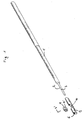
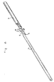
- the tool of the present invention comprises:
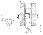
- the milling cutter 4 is housed inside the opening 10 of the guide sleeve 5, and the whole assembly is applied on round 2.
- the longitudinal bore 6 of the guide sleeve by being offset relatively to the axis by a length at least equal to the thickness of tube 7 fastened to the tube plate 8, allows the teeth of milling cutter 4 to protrude by a length identical to its offset and to grind the tube according to the intersection 9.
- the milling-cutter-holder shank is connected to an operating machine, such as, e.g., a drill, and the milling-cutter-housing guide sleeve is slid inside the tube.
- an operating machine such as, e.g., a drill
- the milling cutter On actuating the drill, the milling cutter, which operates on its end, removes a portion of the tube, and the guide sleeve, by being not constrained to the milling-cutter-holder shank, does not rotate and allows the milling cutter to wear away a straight length of tube.
Landscapes
- Engineering & Computer Science (AREA)
- Mechanical Engineering (AREA)
- Milling Processes (AREA)
- Drilling Tools (AREA)
- Sawing (AREA)
- Cutting Tools, Boring Holders, And Turrets (AREA)
- Automatic Assembly (AREA)
- Hand Tools For Fitting Together And Separating, Or Other Hand Tools (AREA)
Applications Claiming Priority (2)
| Application Number | Priority Date | Filing Date | Title |
|---|---|---|---|
| IT2326585 | 1985-12-18 | ||
| IT23265/85A IT1186737B (it) | 1985-12-18 | 1985-12-18 | Metodo per l'estrazione non distruttiva di tubi da scambiatori di calore ed utensile adatto allo scopo |
Publications (3)
| Publication Number | Publication Date |
|---|---|
| EP0228025A2 EP0228025A2 (en) | 1987-07-08 |
| EP0228025A3 EP0228025A3 (en) | 1989-03-22 |
| EP0228025B1 true EP0228025B1 (en) | 1992-06-17 |
Family
ID=11205437
Family Applications (1)
| Application Number | Title | Priority Date | Filing Date |
|---|---|---|---|
| EP86117530A Expired - Lifetime EP0228025B1 (en) | 1985-12-18 | 1986-12-17 | Method for the non-destructive removal of tubes from heat exchangers and tool useful to that purpose |
Country Status (8)
| Country | Link |
|---|---|
| US (1) | US4924588A (it) |
| EP (1) | EP0228025B1 (it) |
| JP (1) | JPS62157739A (it) |
| KR (1) | KR870005753A (it) |
| BR (1) | BR8605949A (it) |
| CA (1) | CA1305344C (it) |
| DE (1) | DE3685734T2 (it) |
| IT (1) | IT1186737B (it) |
Families Citing this family (3)
| Publication number | Priority date | Publication date | Assignee | Title |
|---|---|---|---|---|
| ES2211665T3 (es) * | 1999-12-29 | 2004-07-16 | Concast Standard Ag | Procedimiento y dispositivo para la mecanizacion de paredes de cavidad de lingoteras de colada continua. |
| GB201116287D0 (en) * | 2011-09-21 | 2011-11-02 | Airbus Operations Ltd | Method and device for removing a sleeve from a bore |
| CN109974506A (zh) * | 2019-03-12 | 2019-07-05 | 哈电集团(秦皇岛)重型装备有限公司 | 一种移出组件及管束组件取管换管方法 |
Family Cites Families (12)
| Publication number | Priority date | Publication date | Assignee | Title |
|---|---|---|---|---|
| US1795553A (en) * | 1928-10-18 | 1931-03-10 | Fred I Getty | Offset-cutting tool |
| US2000824A (en) * | 1933-09-13 | 1935-05-07 | Crockett William Barnes | Recessing cutter |
| US2341322A (en) * | 1942-01-14 | 1944-02-08 | Sullivan Machinery Co | Drill guide |
| US2401490A (en) * | 1944-08-21 | 1946-06-04 | Glenn L Martin Co | Keyseating tool |
| DE924984C (de) * | 1952-04-19 | 1955-03-10 | Kronprinz Ag | Vorrichtung zum Entfernen des Innengrates an der Laengsnaht elektrisch geschweissterRohre |
| US2834106A (en) * | 1956-11-19 | 1958-05-13 | Diamond Alkali Co | Apparatus for splitting tubes |
| US2949064A (en) * | 1958-09-15 | 1960-08-16 | Adcock Kenneth | Tool for roughening walls of bowling ball finger holes |
| US3729806A (en) * | 1968-09-06 | 1973-05-01 | Carrier Corp | Method for tube removal |
| US3979816A (en) * | 1975-01-17 | 1976-09-14 | Green Bernard S | Boiler tube extractor and method |
| JPS53112A (en) * | 1976-06-23 | 1978-01-05 | Nippon Hamondo Kk | Tempo indicator for automatic rhythm playing device |
| SU854610A1 (ru) * | 1979-01-11 | 1981-08-15 | Предприятие П/Я А-3487 | Устройство дл обработки труб с внутренней стороны |
| US4646413A (en) * | 1985-06-18 | 1987-03-03 | Tri Tool Inc. | Tube extractor drill jig |
-
1985
- 1985-12-18 IT IT23265/85A patent/IT1186737B/it active
-
1986
- 1986-12-04 BR BR8605949A patent/BR8605949A/pt not_active IP Right Cessation
- 1986-12-12 US US06/941,087 patent/US4924588A/en not_active Expired - Fee Related
- 1986-12-16 CA CA000525468A patent/CA1305344C/en not_active Expired - Fee Related
- 1986-12-17 KR KR860010807A patent/KR870005753A/ko not_active Ceased
- 1986-12-17 EP EP86117530A patent/EP0228025B1/en not_active Expired - Lifetime
- 1986-12-17 JP JP61299077A patent/JPS62157739A/ja active Pending
- 1986-12-17 DE DE8686117530T patent/DE3685734T2/de not_active Expired - Lifetime
Also Published As
| Publication number | Publication date |
|---|---|
| EP0228025A3 (en) | 1989-03-22 |
| EP0228025A2 (en) | 1987-07-08 |
| BR8605949A (pt) | 1987-09-15 |
| CA1305344C (en) | 1992-07-21 |
| US4924588A (en) | 1990-05-15 |
| JPS62157739A (ja) | 1987-07-13 |
| DE3685734D1 (de) | 1992-07-23 |
| IT8523265A0 (it) | 1985-12-18 |
| KR870005753A (ko) | 1987-07-07 |
| IT1186737B (it) | 1987-12-16 |
| DE3685734T2 (de) | 1992-12-24 |
Similar Documents
| Publication | Publication Date | Title |
|---|---|---|
| US5061126A (en) | Hole saw and mandrel assembly | |
| CA1130622A (en) | Portable pipe end bevelling tool | |
| US4459883A (en) | Portable machine tool for preparing pipe joints for welding | |
| DE2610386A1 (de) | Radial verstellbares dreh-schneidwerkzeug | |
| BE899201A (fr) | Mandrin pour percage avec percussion. | |
| EP0228025B1 (en) | Method for the non-destructive removal of tubes from heat exchangers and tool useful to that purpose | |
| US4333727A (en) | Composite rotary tool including hole forming means and a deburrer or chamferer | |
| CA1265989A (en) | Flail tube cutter | |
| GB2187422A (en) | Vehicle steering column | |
| US4889454A (en) | Portable power tool for milling tube ends | |
| WO1983003376A1 (en) | Reaming and counterboring cutting tool | |
| US4997322A (en) | Automobile body reamer tool | |
| CN2186128Y (zh) | 用于复合材料的开孔器 | |
| US2853904A (en) | Core cutter | |
| EP0362989B1 (en) | Portable power tool for milling tube ends | |
| US4548530A (en) | Reboring tool | |
| US5467657A (en) | Method and device for core sampling steel | |
| US3729806A (en) | Method for tube removal | |
| GB2074060A (en) | Forming holes of a predetermined diameter in a set of superimposed sheets | |
| US4890945A (en) | Rotary die cylinder bearer attachment | |
| JP2614372B2 (ja) | 分割可能なダイ | |
| GB1559046A (en) | Drill tool | |
| US20250345866A1 (en) | Multi-function beveling and weld bead removal tool | |
| US303556A (en) | Dennis bushoe | |
| RU2108191C1 (ru) | Фреза |
Legal Events
| Date | Code | Title | Description |
|---|---|---|---|
| PUAI | Public reference made under article 153(3) epc to a published international application that has entered the european phase |
Free format text: ORIGINAL CODE: 0009012 |
|
| AK | Designated contracting states |
Kind code of ref document: A2 Designated state(s): BE DE FR GB NL SE |
|
| PUAL | Search report despatched |
Free format text: ORIGINAL CODE: 0009013 |
|
| AK | Designated contracting states |
Kind code of ref document: A3 Designated state(s): BE DE FR GB NL SE |
|
| 17P | Request for examination filed |
Effective date: 19890620 |
|
| RAP1 | Party data changed (applicant data changed or rights of an application transferred) |
Owner name: MONTEDIPE S.R.L. |
|
| 17Q | First examination report despatched |
Effective date: 19900801 |
|
| RAP1 | Party data changed (applicant data changed or rights of an application transferred) |
Owner name: ECP ENICHEM POLIMERI S.R.L. |
|
| GRAA | (expected) grant |
Free format text: ORIGINAL CODE: 0009210 |
|
| AK | Designated contracting states |
Kind code of ref document: B1 Designated state(s): BE DE FR GB NL SE |
|
| REF | Corresponds to: |
Ref document number: 3685734 Country of ref document: DE Date of ref document: 19920723 |
|
| ET | Fr: translation filed | ||
| PLBE | No opposition filed within time limit |
Free format text: ORIGINAL CODE: 0009261 |
|
| STAA | Information on the status of an ep patent application or granted ep patent |
Free format text: STATUS: NO OPPOSITION FILED WITHIN TIME LIMIT |
|
| 26N | No opposition filed | ||
| PGFP | Annual fee paid to national office [announced via postgrant information from national office to epo] |
Ref country code: GB Payment date: 19941207 Year of fee payment: 9 |
|
| PGFP | Annual fee paid to national office [announced via postgrant information from national office to epo] |
Ref country code: DE Payment date: 19941208 Year of fee payment: 9 |
|
| PGFP | Annual fee paid to national office [announced via postgrant information from national office to epo] |
Ref country code: FR Payment date: 19941209 Year of fee payment: 9 |
|
| PGFP | Annual fee paid to national office [announced via postgrant information from national office to epo] |
Ref country code: SE Payment date: 19941215 Year of fee payment: 9 |
|
| PGFP | Annual fee paid to national office [announced via postgrant information from national office to epo] |
Ref country code: NL Payment date: 19941231 Year of fee payment: 9 |
|
| EAL | Se: european patent in force in sweden |
Ref document number: 86117530.5 |
|
| PGFP | Annual fee paid to national office [announced via postgrant information from national office to epo] |
Ref country code: BE Payment date: 19950207 Year of fee payment: 9 |
|
| PG25 | Lapsed in a contracting state [announced via postgrant information from national office to epo] |
Ref country code: GB Effective date: 19951217 |
|
| PG25 | Lapsed in a contracting state [announced via postgrant information from national office to epo] |
Ref country code: SE Effective date: 19951218 |
|
| PG25 | Lapsed in a contracting state [announced via postgrant information from national office to epo] |
Ref country code: BE Effective date: 19951231 |
|
| BERE | Be: lapsed |
Owner name: ENICHEM POLIMERI S.R.L. ECP Effective date: 19951231 |
|
| PG25 | Lapsed in a contracting state [announced via postgrant information from national office to epo] |
Ref country code: NL Effective date: 19960701 |
|
| GBPC | Gb: european patent ceased through non-payment of renewal fee |
Effective date: 19951217 |
|
| PG25 | Lapsed in a contracting state [announced via postgrant information from national office to epo] |
Ref country code: FR Effective date: 19960830 |
|
| NLV4 | Nl: lapsed or anulled due to non-payment of the annual fee |
Effective date: 19960701 |
|
| PG25 | Lapsed in a contracting state [announced via postgrant information from national office to epo] |
Ref country code: DE Effective date: 19960903 |
|
| REG | Reference to a national code |
Ref country code: FR Ref legal event code: ST |