EP0228030A2 - Machine de forgeage - Google Patents
Machine de forgeage Download PDFInfo
- Publication number
- EP0228030A2 EP0228030A2 EP86117589A EP86117589A EP0228030A2 EP 0228030 A2 EP0228030 A2 EP 0228030A2 EP 86117589 A EP86117589 A EP 86117589A EP 86117589 A EP86117589 A EP 86117589A EP 0228030 A2 EP0228030 A2 EP 0228030A2
- Authority
- EP
- European Patent Office
- Prior art keywords
- pistons
- machine according
- pieces
- piston
- plunger
- Prior art date
- Legal status (The legal status is an assumption and is not a legal conclusion. Google has not performed a legal analysis and makes no representation as to the accuracy of the status listed.)
- Granted
Links
- 238000005242 forging Methods 0.000 title claims abstract description 35
- 230000008878 coupling Effects 0.000 claims description 12
- 238000010168 coupling process Methods 0.000 claims description 12
- 238000005859 coupling reaction Methods 0.000 claims description 12
- 238000006073 displacement reaction Methods 0.000 claims description 11
- 238000000034 method Methods 0.000 claims description 6
- 230000008569 process Effects 0.000 claims description 5
- 230000000149 penetrating effect Effects 0.000 claims description 4
- 230000009471 action Effects 0.000 claims description 3
- 230000001419 dependent effect Effects 0.000 claims 1
- 210000003128 head Anatomy 0.000 description 20
- 230000001681 protective effect Effects 0.000 description 4
- 230000008901 benefit Effects 0.000 description 3
- 238000007789 sealing Methods 0.000 description 2
- 230000000712 assembly Effects 0.000 description 1
- 238000000429 assembly Methods 0.000 description 1
- 230000005540 biological transmission Effects 0.000 description 1
- 230000000295 complement effect Effects 0.000 description 1
- 230000006835 compression Effects 0.000 description 1
- 238000007906 compression Methods 0.000 description 1
- 230000007717 exclusion Effects 0.000 description 1
- 239000000463 material Substances 0.000 description 1
- 230000002035 prolonged effect Effects 0.000 description 1
- 239000007921 spray Substances 0.000 description 1
- 230000007704 transition Effects 0.000 description 1
- XLYOFNOQVPJJNP-UHFFFAOYSA-N water Substances O XLYOFNOQVPJJNP-UHFFFAOYSA-N 0.000 description 1
Images


Classifications
-
- B—PERFORMING OPERATIONS; TRANSPORTING
- B21—MECHANICAL METAL-WORKING WITHOUT ESSENTIALLY REMOVING MATERIAL; PUNCHING METAL
- B21J—FORGING; HAMMERING; PRESSING METAL; RIVETING; FORGE FURNACES
- B21J13/00—Details of machines for forging, pressing, or hammering
- B21J13/02—Dies or mountings therefor
- B21J13/03—Die mountings
-
- B—PERFORMING OPERATIONS; TRANSPORTING
- B21—MECHANICAL METAL-WORKING WITHOUT ESSENTIALLY REMOVING MATERIAL; PUNCHING METAL
- B21J—FORGING; HAMMERING; PRESSING METAL; RIVETING; FORGE FURNACES
- B21J13/00—Details of machines for forging, pressing, or hammering
-
- B—PERFORMING OPERATIONS; TRANSPORTING
- B21—MECHANICAL METAL-WORKING WITHOUT ESSENTIALLY REMOVING MATERIAL; PUNCHING METAL
- B21J—FORGING; HAMMERING; PRESSING METAL; RIVETING; FORGE FURNACES
- B21J7/00—Hammers; Forging machines with hammers or die jaws acting by impact
- B21J7/02—Special design or construction
- B21J7/14—Forging machines working with several hammers
Definitions
- Forging machines are used to forge workpieces with a round, square, rectangular or similar cross-section that are emphasized along the longitudinal axis and are usually equipped with four rams, which act simultaneously on the workpiece and are fitted with tools.
- the economic use of these forging machines requires a high degree of flexibility, which is why the workpieces should always be manufactured without a form bond between tool and workpiece and without changing tools. Accordingly, tool widths with a flat effective surface are used.
- the cross section enclosed by the tools in the stroke end position results in a cross section with an edge length corresponding to the tool width. Smaller enclosed cross sections cannot and larger enclosed cross sections can only be forged in open caliber and therefore not fully.
- the invention is based on forging machines with four rams arranged in a x-shaped manner in a working plane perpendicular to the longitudinal axis of the workpiece and movable transversely to the longitudinal axis of the workpiece, which rams themselves as part of a piston Cylinder unit or from a drive unit, in particular a piston-cylinder unit, are movable and are operatively connected to tools which form a closed caliber in the stroke end position near the center, each tool having the unused width of its working surface from a side surface of an adjacent tool is covered and in turn covers with one of its side surfaces the unused width of the working surface of the other adjacent tool, it being the object of the invention to avoid oblique or swinging movements of the tools and the resulting sliding movements between the tools and the workpiece.
- the drive units are arranged to act radially to the longitudinal axis of the workpiece, adjusting means are provided for setting and displaying the stroke end position, and each tool is in a support formed from the ram and a cross piece by means of an adjusting device, depending on the one determining the forging dimension Stroke end position adjustment, adjustable in the working plane from the effective axis of the drive units by the amount which corresponds to half the difference between the total width and the width of the tool used corresponding to the respective caliber.
- a caliber closed in all stroke positions is dispensed with according to the invention, because it was recognized that it is sufficient if the caliber is closed in the stroke end position corresponding to the respective forging dimension, which can be achieved according to the invention by the adjustability of the tools for the drive units.
- piston-cylinder units are used only as drive units for separate plungers or the plungers themselves are designed as parts of the piston-cylinder units, it is advantageous that To dimension piston-cylinder units only for the working stroke and to provide the stroke position adjustment by means of special mechanical adjusting means, as is known per se for the purpose of minimizing the oil volume effective in the hydraulic drive and influencing the dynamic behavior of the forging machine.
- cross pieces equipped with the tools in head pieces of the plunger are adjustable in the working plane at right angles to the plunger axis and can be determined by releasable clamping elements relative to the head pieces, while adjusting devices for moving the cross pieces in the Head pieces with loosened clamping elements between the head pieces and cross pieces are arranged to act.
- the drive and / or display devices for the actuating devices are expediently arranged on the ends of the plungers facing away from the head pieces and connected by coupling to the actuating devices, the couplings passing through the plungers or being arranged parallel to the plungers.
- the tappets are designed as parts (pistons or cylinders) of piston-cylinder units provided for the tappet drive. If the tappets are designed as pistons, it is advisable to connect the cylinders to the machine frame for direct guidance of the pistons and to adjust the stroke position by means of plugs which are adjustable in the cylinders and form the bottoms of the cylinders. If, on the other hand, the tappets are designed as cylinders, which are thus movably guided in the machine frame, the pistons are to be provided for adjusting the stroke position by being arranged in the machine frame so as to be adjustable.
- Both the pistons serving as plungers can be provided with shafts penetrating the plugs, and the cylinders serving as plungers can be provided with the shafts penetrating as pistons.
- These shafts can be designed for the stroke limitation and the retraction of the pistons or cylinders (tappets) and can also be axially pierced so that, according to a further feature of the invention, they can accommodate the couplings for the geared connection of the actuating devices with their drive and / or display devices .
- racks connected to the cross pieces and pinions engaging in them and coupling to the pinions can be provided as adjusting devices, the shafts being guided through the central bores in the tappets or laterally along the tappets.
- a precondition for a safe working method is that an unwanted displacement of the cross pieces in relation to the ram heads is excluded.
- a design of the ram head and cross piece with interlocking fine toothing is provided, whereby an infinitely variable adjustment is excluded, but the fine toothing gradation of the setting meets practical needs.
- plunger heads and cross pieces are provided with corresponding grooves and strips inserted into the grooves and provided with teeth.
- the clamping elements for fixing the crosspieces relative to the plunger heads can be designed in a known manner (for example DE-Gbm 7807825, DE-OS 29 623) by providing clamping bolts which are provided with a crosspiece, plunger head and a spring-encircling collar, one of which is known as Piston-formed collar underlaid by the spring can be acted upon against the force of the spring, with the special feature that when the pistons are acted upon and the clamping elements are released, the drives for the displacement of the crosspieces relative to the plunger heads and for stroke position adjustment can be unlocked at the same time.
- a known manner for example DE-Gbm 7807825, DE-OS 29 623
- a valve is open-controlled, which allows compressed air to pass through the gaps formed between the cross pieces and plunger heads. The compressed air flow prevents dirt from entering the gaps.
- cross pieces in the machine frame are guided in the working plane at right angles to the ram axis and can be fixed by releasable clamping elements relative to the machine frame, the adjusting devices for displacing the cross pieces in the machine frame when the clamping devices are released between the machine frame and the cross pieces are arranged to act and the plungers equipped with the tools are guided in the cross pieces so as to be axially movable and are each connected to a drive unit.
- piston-cylinder units for driving the plunger are arranged in a stationary manner in the machine frame, are arranged radially to the longitudinal axis of the workpiece Tappets connected by the adjustment of the cross pieces with the tappets compensating, but transmitting the axial forces from the pistons to the tappets.
- a simple, reliably working coupling of the piston and tappet consists of a T or dovetail groove in the tappet end face, T or dovetail sliding pieces guided therein and pistons connected to the sliding pieces and of pistons guided in cylinder bores in the cross member over yoke pieces to exciting tie rods, the loading of the pistons being interrupted during the displacement of the cross pieces by the adjusting devices and the couplings thus being released.
- the piston-cylinder units designed in connection with mechanical adjusting means, in particular screw drives for the stroke position adjustment form the further advantage that, together with a mechanical limitation of the working stroke, the mechanical fixing the stroke position so that the stroke end position and the setting of the tools can be precisely coordinated with one another via the cross pieces, as is provided according to a further feature of the invention.
- the lateral displacements of the cross pieces relative to the ram heads or the machine frame and the stroke end positions of the rams are measured and can be set as a function of a caliber dimension that has been entered and programmed via a process computer.
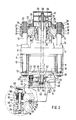
- the workpiece 1 can be seen in its cross section, which traverses the length of the forging machine and is thereby stretched by the tools 2.
- the tools 2 are cross-lock-like, that is to say offset according to the cross-section to be forged, and an adjacent tool 2 is arranged overlapping around the workpiece 1 with their working surface.
- the respective center offset of the tools 2 determines the possible approximation of the tools 2 and thus the smallest cross section to be forged with a specific tool setting, which in turn determines the inner reversal points of the stroke movement of the tools 2, ie the stroke end positions of the respective stroke positions.
- the tools 2 are carried by plungers 3, which are designed as pistons and are movably guided in cylinder 4.
- plungers 3 are designed as pistons and are movably guided in cylinder 4.
- four cylinders 4 are arranged in a frame 5.
- the frame 5 is anchored to the foundation 7 with foot pieces 6.
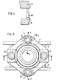
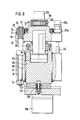
- FIGS. 2 to 5 The details of the units formed from the tappets or pistons 3 and the cylinders 4 are shown in FIGS. 2 to 5.
- the cylinders 4 are provided with flanges 8 and the frames 5 per cylinder 4 are provided with four eyes 9.
- the tie rods 10 are also extended to spindles 13 with a threaded shaft 14.
- Each cylinder 4 has a through bore which is closed on one side by a plug 15, which includes a seal 16.
- the plug 15 is fixedly connected to a yoke plate 17, which are provided with four bores 18 for the passage of the spindles 13 to the tie rods 10.
- the bores 18 are expanded to bearing bores in which nuts 20 provided on the outside with teeth 19 and on the inside with threads are rotatably supported and held by a split bearing plate 21.
- the four nuts 20 of a yoke plate 17 are rotated together by a ring gear 22 which is rotatable with balls 23 on a bearing ring 24 centered and fastened on the yoke plate 17.
- Two of the nuts 20 are extended with a sleeve-shaped extension 25, which give space to the threaded shafts 14 and are provided with dome teeth 26 at their ends. They are in engagement with coupling disks 27 on the driven side of gearboxes 28 through which the nuts 20 provided with the sleeve projections 25 can be rotated and locked directly and the two other nuts 20 indirectly via the ring gear 22 and the pinion 19.
- the nuts 20 rotate, they move along the threaded shafts 14 on the spindles 13 and adjust the stopper 15 in the bore of the cylinder 4 in the axial direction via the yoke plate 17.
- a plunger 3 formed from a piston 3 and also carrying the tool 2 is axially movable.
- the piston 3 is provided with a round shaft 29 and at the transition from the piston 3 to the shaft 29 with a square section 30. Furthermore, the shaft 29 is provided with a collar 31 at its end.
- the plug 15 is provided with a corresponding round and square bore in the region of the section 30, the square section 30 guiding the piston 3 in the corresponding square bore of the plug 15 against rotation.
- the pressure medium space in the cylinder 4 between the piston 3 and the plug 15 is closed by the seals 32 and 33.
- the axial movement of the piston 3 is limited, on the one hand, by its stop on the plug 15 and, on the other hand, by the collar 31 on the piston shaft 29, by the collar 31 striking the rear face 34 of the plug 15.
- the collar 31 on the piston shaft 29 can be axially adjustable, whereby the stroke of the piston 3 limited by the stops is also adjustable.
- the stroke position of the piston 3, however, is adjustable by the previously described adjustment of the yoke plate 17 by turning the nuts 20 on the threaded shafts 14 of the spindles 13.
- the plug 15 is drilled out from the rear end face to a cylinder space 35.
- piston-cylinder units 40 are arranged between the flange 8 of the cylinder 4 and the yoke plate 17, by means of which the constant contact of the threaded nuts 20 on the threaded shaft 14 is maintained in the working pressure direction in order to support the stopper 15 without play guarantee.
- a protective jacket 41 is placed on the piston 3 and surrounds the cylinder 4 with little play on the outside (see in particular FIG. 3). Compressed air is blown into the protective jacket 41, which emerges at the annular gap 42 between the protective jacket 41 and the cylinder 4 and thus prevents the ingress of dirt into the space 43 covered by the protective jacket 4.
- each tappet or piston 3 is connected on the head side to a tappet head 44.
- a guide groove 45 is machined, in which a cross piece 46 is slidably guided in the working plane transversely to the longitudinal axis of the workpiece.
- the plunger 3 with its plunger heads 44 together with the cross pieces 46 form the tools 2 supporting supports.
- grooves 47 are connected to the plunger head 44 strips 50 and in the grooves 48 connected to the crosspiece 46 strips 51 are inserted, the strips 50 and 51 are provided on their facing surfaces with fine teeth 52 which are in engagement with each other.
- a toothed rack 53 is inserted into the groove 49 and fastened in it.
- a pinion 54 engages in this toothed train 53, which pinion is connected to one end of a shaft 55.
- the shaft 55 is rotatably mounted in a bearing bush 56 in the tappet head 44, passes through the tappet or piston 3 and piston shaft 29 in an axial bore 57 and is provided at its other end with a spline toothing 58 with which it engages in the correspondingly toothed bore a worm wheel 59 engages in a rotationally fixed but axially displaceable manner.
- the worm wheel 59 and an associated worm shaft 60 are mounted in a gear housing 61 connected to the yoke plate 17 and can be driven by a drive (not shown).
- clamping elements are provided which consist of a clamping bolt 62, a piston 63 and a nut 64 as the bundle of the clamping bolt 62 which surrounds the plunger head 44, the cross piece 46 and a spring 65.
- the crosspiece 46 which is displaceable relative to the plunger head 44, is provided with slots 66 in the direction of displacement, in which two-part clamping blocks 67 can be displaced.
- the springs 65 formed from a package of disc springs, which are supported in the plunger head 44, press against the pistons 63 of the clamping bolts 62 via collar bushings 68, so that the plunger head 44 and crosspiece 46 are braced against one another via the nuts 64 and clamping stones 67.
- the cross piece 46 By acting on the pistons 63 in the cylinders 69 connected to the plunger head 44, the cross piece 46 is pushed by the plunger head 44 by the plunger head 44 to such an extent that the teeth 52 on the pairs of strips 50, 51 disengage while the Cross piece 46 remains guided in the guide groove 45, for which purpose the guide groove 45 is held sufficiently deeper than the toothing 52 and the collar bushes 68 find a corresponding stroke limitation in the offset bores accommodating the spring assemblies 65.
- the crosspiece 46 can then be adjusted relative to the plunger head 44 by means of the drive via the worm shaft 60, the worm wheel 59, the shaft 55, the pinion 54, and the toothed rack 53.
- a valve (not shown) is opened, through which compressed air enters the closed gear housing 61 and from there through the bore 57 and branch bores 70 into the gap formed between the plunger head 44 and the crosspiece 46 which is being deposited, exits there and preventing dirt (sinter and the like) from entering the gap.
- Tools 2 are interchangeably connected to cross piece 46.
- the largest cross section (Q) to be forged is determined by the width of the tools 2, as shown in FIGS. 1 and 3 in dotted lines.
- Smaller cross-sections such as the square cross-section (q) shown in full lines or a rectangular cross-section shown in FIG. 1a, require the crosspieces 46 to be displaced with the tools 2, so that the working surfaces of one tool 2 each have the unused tool width with the side surface each intersect an adjacent tool 2, the lateral offset (V) being half the difference between the full tool width and the used tool width.
- the setting of the tools 2 to a specific cross-section must go hand in hand with the setting of the plunger or piston 3 to the specific cross-sectional dimension as the internal dimension of the stroke position by which the approximation of opposite tools 2 is determined.
- the drives 28 for the stroke position adjustment and the drives via the worm shafts 60 for the lateral displacement (V) of the cross pieces 46 with the tools 2 are coupled to sensors for displaying the respective setting of the stroke position and the offset (V) (actual value). Automation can also take place via process computers via setpoint transmitters with predefined or preprogrammed setpoints; including mutual locking of mutually exclusive operations and settings.
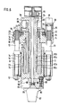
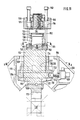
- the plungers are designed as cylinders 72, one of which is shown in FIG. 6.
- the cylinders 72 are guided in the machine frame 73 in guide bushes 74 on the outside of round cylinders 72, with the guide bushes 74 taking the place of outside, non-circular flattened cylinders, guide plates of appropriate shape.
- Each cylinder 72 forms a functional unit with a piston 75, the piston 75 being supported on a yoke plate 76.
- the adjustment of the yoke plate 76 relative to the machine frame 73 is the same as that of the yoke plate 17 relative to the machine frame 5 in the first exemplary embodiment, the corresponding parts being identified identically, so that reference is made to their description in the first exemplary embodiment.
- the piston 75 is designed as an annular piston and the cylinder 72 is accordingly provided with a shaft 77 which passes through the annular piston 75. At its end, the shaft 77 is provided with a traverse 78. On the yoke plate 76 with the piston 75, a plate 79 is placed, which is provided with cylinder bores 80. Pistons 81 in the cylinder bores 80 can be acted upon to retract the cylinder 72 and the working stroke of the cylinder 72 is limited on the one hand by the annular piston 75 and on the other hand by the pistons 81.
- bushings 82a, b, and c are provided between the annular piston 75 and the cylinder 72 with a shaft 77, and sealing rings 82d and e are provided for sealing.
- the design of the piston 75 as an annular piston and the shaft 77 offer the possibility of a tool adjustment through a bore 83 in the shaft 77.
- a shaft 84 is provided which can be rotated and locked via a worm drive 85.
- a pinion 85 connected to the shaft 84 is in engagement with a toothed rack 86 in the tool 87.
- a cross piece 89 carrying the tool 87 is fastened to a head piece 90 by means of clamping devices 89, the head piece 90 with the Cylinder 72 is connected. When the clamping devices 88 are released, the tool 87 can be adjusted transversely to the ram axis with its cross piece 89 on the head piece 90 in the working plane.
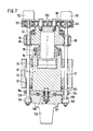
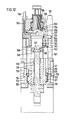
- the plungers are designed as cylinders 91, as shown in FIGS. 7, 8 and 9.
- Each cylinder 91 is guided in the machine frame 92.
- double-acting pistons 93 are provided which are connected to the yoke plates 95 via piston rods 94.
- each cylinder 91 is closed off by a cover 96 towards the piston rod 94, the cover 96 also limiting the stroke of the cylinder 91 to the working stroke.
- the stroke position is adjusted via the yoke plate 95 in a manner similar to that in the first and second exemplary embodiments.
- the ring gear 22 can be driven and fixed by motors 28a via pinions 20a.
- a tool adjustment by a centrally arranged shaft as in the first and second embodiment would be possible - for this purpose the piston 93 would have to be extended with a pin into a bore penetrating the bottom of the cylinder 91 and the cylinder 91 to 7, the tool adjustment is provided by two external shafts 97, which are mounted in bearings 98 fastened to the yoke plate 95 and follow the movement of the yoke plate 95.
- a gear transmission 99 is placed on the yoke plate 95 and connects the shafts 97 driven by motors 102 via two intermediate gears 100 and gears 101.
- the waves 97 are also mounted in a head piece 93 to the cylinder 91 in bushes 104 and connected with pinions 105.
- a cross piece 107 carrying the tool 106 which is guided in the head piece 103 and is detachably connected to the head piece 103 by a clamping device 108, is provided on both longitudinal sides with a toothing 109, in which the pinions 105 engage. When the clamping device 108 is released, the tool 106 with its cross piece 107 on the head piece 103 can be adjusted transversely to the ram axis in the working plane.
- FIGS. 10 to 15 the boundaries of the largest and smallest cross section of a workpiece 111 to be forged can be seen from FIGS. 10 and 11.
- the tools 112 are shown in the setting for the largest cross section to be forged in their outer stroke end position, that is to say in the fully open position and dotted in the setting for the smallest cross section to be forged in their inner stroke end position, that is to say with the caliber closed.
- the tools 112 are carried by plungers 113, which are guided axially movably in cross pieces 114, while the cross pieces 114 are in turn guided in the working plane and at right angles to the axis of the plungers 113 in the machine frame 115.
- the machine frame 115 is anchored to the foundation 117 with foot pieces 116.
- the latter is provided with strips 118 and also with grooves 119 for receiving locking pieces 120.
- the strips 118 and the strikers together form guide grooves in which the cross pieces 114 slide with strips 121 which are covered with wear plates.
- Wedge pieces 122 are between the strips 121 and the strikers 120 are arranged.
- the wedge pieces 122 are connected to spring-loaded tie rods and clamp the cross pieces 114 on their strips 121 in the guide grooves formed by the strips 118 and closing pieces 120, the wedge pieces 122 against the force of the springs of piston-cylinder units 123 for displacing the Cross pieces 114 can be solved.
- the cross pieces 114 are displaced by spindle drives, consisting of spindles 124 and drive gears 125 with drive motors 126, the drive gears 125 being formed from the outside with worm teeth, which are rotated by worm shafts.
- spindle drives consisting of spindles 124 and drive gears 125 with drive motors 126, the drive gears 125 being formed from the outside with worm teeth, which are rotated by worm shafts.
- the plungers 113 have an I-shaped cross section and are guided in axially movable fashion in corresponding recesses 128 of the cross pieces 114 by plates 129, as can be seen in particular from FIGS. 11, 12 and 15.
- the plunger 113 is driven by pistons 130 which are guided in cylinder 131.
- the pistons 130 are provided with a collar 132 through which the stroke of the pistons 130 into the cylinder 131 is mechanically limited.
- Each cylinder 131 is closed off by a cover 133 fastened to it with screws.
- Each cover 133 is provided with a threaded pin 134, with which it is supported in a traverse 136 via a nut 135.
- Tie rods 137 which are screwed into the bores of the machine frame 115 with threaded pins 138, connect the cross members 136 to the machine frame 115.
- the threaded nut 135 is designed as a worm wheel and a worm of a worm shaft 139 engages in the worm toothing, which worm is driven by a motor 140 for the purpose of axial adjustment of the cylinder 131 with the piston 130, that is to say that it can be driven to adjust the stroke position of the associated tool 112.
- cylinders 141 are also attached, in which pistons 142 are guided, which act with their piston rods 143 via lugs 144 of the cylinders 131 on them, the cylinder cover 132 and the threaded pin 133 and the constant contact of the threaded pin 133 in the nuts 134 underneath Maintain exclusion of any game.
- the piston 130 in the cylinder 131 is acted upon by an epee tube 145, which is attached to the cylinder cover 133 and is guided and sealed in the crossmember 136, and the pipeline 146.
- the pistons 130 are provided with spherical pressure surfaces 147, with which they press onto the plunger 113 via pressure pans 148 which are likewise provided with spherical pressure surfaces.
- the adjustability of the cross pieces 114 with the plungers 113 in the working plane at right angles to the plunger axis requires a coupling of the pistons 130 with the plungers 113 to compensate for this displacement.
- the plungers 113 are connected to their end faces with two strips 149, so that there is a T-groove on the end face. T-shaped sliders 150 are inserted into this T-groove, which are connected to a ring 151 and, via this, to tie rods 152.
- the tie rods 152 are passed through the cross member 136 and connected above the cross members 136 by yoke pieces 153.
- the cross members 136 are provided with cylinder bores 154 in which pistons 155 are guided, which act on the tie rods 152 via the yoke pieces 153.
- the pistons 155 When the pistons 155 are loaded, the T-shaped sliders 150 are clamped in the T-grooves between the strips 149, whereby the pistons 130 are connected to the plungers 113. At the same time, the pistons 155 serve as retraction pistons for the pistons 130. If the cross pieces 114 are to be adjusted with the plungers 113, the motor 126 must be actuated and at the same time the action on the pistons 155 is interrupted.
- the setting of the tools 112 to a specific cross-section is accompanied by the setting of the plunger 113 with the pistons 130 and cylinder 131 to the corresponding stroke end position, which takes place above the motor 140.
- the displacement of the associated tool 112 can be determined as the actual value via the worm shaft 139 as the encoder and can be set via the setpoint generator.
Landscapes
- Engineering & Computer Science (AREA)
- Mechanical Engineering (AREA)
- Forging (AREA)
Priority Applications (1)
| Application Number | Priority Date | Filing Date | Title |
|---|---|---|---|
| AT86117589T ATE62838T1 (de) | 1986-01-02 | 1986-12-17 | Schmiedemaschine. |
Applications Claiming Priority (12)
| Application Number | Priority Date | Filing Date | Title |
|---|---|---|---|
| DE3600018 | 1986-01-02 | ||
| DE3600018 | 1986-01-02 | ||
| DE3600178 | 1986-01-07 | ||
| DE3600178 | 1986-01-07 | ||
| DE3600690 | 1986-01-13 | ||
| DE3600690 | 1986-01-13 | ||
| DE3627843 | 1986-08-16 | ||
| DE3627843 | 1986-08-16 | ||
| DE3630170 | 1986-09-04 | ||
| DE3630170 | 1986-09-04 | ||
| DE3631439 | 1986-09-16 | ||
| DE3631439 | 1986-09-16 |
Publications (3)
| Publication Number | Publication Date |
|---|---|
| EP0228030A2 true EP0228030A2 (fr) | 1987-07-08 |
| EP0228030A3 EP0228030A3 (en) | 1988-09-07 |
| EP0228030B1 EP0228030B1 (fr) | 1991-04-24 |
Family
ID=27544414
Family Applications (1)
| Application Number | Title | Priority Date | Filing Date |
|---|---|---|---|
| EP86117589A Expired - Lifetime EP0228030B1 (fr) | 1986-01-02 | 1986-12-17 | Machine de forgeage |
Country Status (4)
| Country | Link |
|---|---|
| US (1) | US4796456A (fr) |
| EP (1) | EP0228030B1 (fr) |
| JP (1) | JPH08273B2 (fr) |
| DE (1) | DE3678918D1 (fr) |
Cited By (5)
| Publication number | Priority date | Publication date | Assignee | Title |
|---|---|---|---|---|
| EP0653257A1 (fr) * | 1993-12-16 | 1995-05-17 | SMS HASENCLEVER GmbH | Machine à forger |
| EP0653258A1 (fr) * | 1993-12-16 | 1995-05-17 | SMS HASENCLEVER GmbH | Machine à forger |
| EP1005933A1 (fr) * | 1998-09-22 | 2000-06-07 | SMS EUMUCO GmbH | Machine de forgeage à poinçons multiples |
| CN110548827A (zh) * | 2018-05-31 | 2019-12-10 | 宝钢特钢有限公司 | 一种提高镍基耐蚀合金锻坯成材率的锻造方法 |
| AT519807A3 (de) * | 2017-03-22 | 2022-10-15 | Sms Group Gmbh | Radial-Schmiedeanlage |
Families Citing this family (17)
| Publication number | Priority date | Publication date | Assignee | Title |
|---|---|---|---|---|
| ATE58657T1 (de) * | 1986-09-16 | 1990-12-15 | Hasenclever Maschf Sms | Schmiedemaschine. |
| DE4143175A1 (de) * | 1991-12-30 | 1993-07-01 | Hasenclever Maschf Sms | Schmiedemaschine |
| ATE96064T1 (de) * | 1991-12-30 | 1993-11-15 | Hasenclever Maschf Sms | Schmiedemaschine. |
| DE4143176A1 (de) * | 1991-12-30 | 1993-07-01 | Hasenclever Maschf Sms | Schmiedemaschine |
| DE4444493A1 (de) * | 1993-12-16 | 1995-06-22 | Hasenclever Maschf Sms | Schmiedemaschine |
| DE4444497A1 (de) * | 1993-12-16 | 1995-06-22 | Hasenclever Maschf Sms | Schmiedemaschine |
| DE4444498A1 (de) * | 1993-12-16 | 1995-06-22 | Hasenclever Maschf Sms | Schmiedemaschine |
| US6290439B1 (en) | 1994-12-30 | 2001-09-18 | Black & Decker, Inc. | Method and apparatus for forming parts from a continuous stock material and associated forge |
| US5842267A (en) * | 1994-12-30 | 1998-12-01 | Black & Decker, Inc. | Method and apparatus for forming parts of a predetermined shape from a continuous stock material |
| AT404441B (de) * | 1996-09-17 | 1998-11-25 | Gfm Holding Ag | Schmiedemaschine |
| JP2000197942A (ja) * | 1998-10-30 | 2000-07-18 | Toyota Motor Corp | 鍛造加工解析方法およびその実行プログラムを記録した媒体 |
| DE102005012297B4 (de) * | 2005-03-17 | 2007-06-14 | Sms Meer Gmbh | Schmiedemaschine |
| US20070271990A1 (en) * | 2006-05-26 | 2007-11-29 | Young Thomas M | Shutter-Type Crimper |
| CN105650053A (zh) * | 2014-11-28 | 2016-06-08 | 富泰华工业(深圳)有限公司 | 气缸 |
| CN107876682B (zh) * | 2017-11-02 | 2019-05-28 | 太原科技大学 | 一种用于径向锻造操作机的传动和制动装置 |
| CN107838355B (zh) * | 2017-11-02 | 2019-05-24 | 太原科技大学 | 一种用蜗杆轴向运动调速与制动的径向锻造操作机 |
| IT201900012960A1 (it) * | 2019-07-26 | 2021-01-26 | Mecolpress S P A | Apparecchiatura per lo stampaggio di materiali. |
Citations (6)
| Publication number | Priority date | Publication date | Assignee | Title |
|---|---|---|---|---|
| DE325985C (de) | 1918-12-25 | 1920-09-22 | Carl A Achterfeldt | Schmiedemaschine mit drei oder mehr in einer Ebene zentral wirkenden Arbeitsbacken |
| DE1953867U (de) | 1966-09-30 | 1967-01-19 | Sack Gmbh Maschf | Schmiedemaschine. |
| US3478565A (en) | 1966-09-30 | 1969-11-18 | Sack Gmbh Maschf | Forging machine |
| DE1953867A1 (de) | 1968-11-08 | 1970-06-11 | Stefan Sowitsch & Co Ing | Gleitfangvorrichtung fuer Fahrstuehle |
| DE1908362A1 (de) | 1969-02-20 | 1970-09-10 | Sack Gmbh Maschf | Schmiedemaschine mit verstellbaren Schmiedesaetteln |
| DE2905623A1 (de) | 1978-04-18 | 1979-10-31 | Sallander Hakan | Befestigungsanordnung |
Family Cites Families (12)
| Publication number | Priority date | Publication date | Assignee | Title |
|---|---|---|---|---|
| DE64549C (de) * | Frau M. GAWRON in Stettin | Reibscheibenkupplung mit Bremse | ||
| DE449558C (de) * | 1926-05-07 | 1927-09-15 | Johannes Ingrisch Dipl Ing | Presse zur Verdichtung oder Querschnittsaenderung von Koerpern aus Metall oder anderen Stoffen |
| DE1050154B (de) * | 1956-03-19 | 1959-02-05 | Champigny Seine Rene Etienne Bujon (Frankreich) | Hämmermaschine zum Herstellen von Profilstäben |
| DE1094075B (de) * | 1959-02-04 | 1960-12-01 | Fertigungstechnik Und Maschb G | Schmiedemaschine zum Vierkantschmieden |
| DE1271513B (de) * | 1962-05-30 | 1968-06-27 | Stevens & Bullivant Ltd | Haemmermaschine mit einem umlaufenden Schwungrad |
| DE1812169A1 (de) * | 1968-12-02 | 1970-06-18 | Sack Gmbh Maschf | Schmiedemaschine |
| DE1908361A1 (de) * | 1969-02-20 | 1970-09-10 | Sack Gmbh Maschf | Schmiedemaschine |
| DE1953123A1 (de) * | 1969-10-22 | 1971-04-29 | Horst Schenk | Werkzeug fuer Schmiedemaschine |
| DE1963979A1 (de) * | 1969-12-20 | 1971-06-24 | Demag Hydraulik Gmbh | Hydraulische Schmiedemaschine fuer das Warmschmieden stab- und stangenfoermiger Werkstuecke |
| JPS5417196B2 (fr) * | 1972-08-31 | 1979-06-28 | ||
| AT329349B (de) * | 1973-11-15 | 1976-05-10 | Gfm Fertigungstechnik | Schnellaufende kurzhub-schmiedepresse |
| JPS62229946A (ja) * | 1986-03-31 | 1987-10-08 | Toshiba Corp | ドライエツチング装置 |
-
1986
- 1986-12-17 EP EP86117589A patent/EP0228030B1/fr not_active Expired - Lifetime
- 1986-12-17 DE DE8686117589T patent/DE3678918D1/de not_active Expired - Lifetime
- 1986-12-29 US US06/947,331 patent/US4796456A/en not_active Expired - Lifetime
-
1987
- 1987-01-05 JP JP62000094A patent/JPH08273B2/ja not_active Expired - Lifetime
Patent Citations (7)
| Publication number | Priority date | Publication date | Assignee | Title |
|---|---|---|---|---|
| DE325985C (de) | 1918-12-25 | 1920-09-22 | Carl A Achterfeldt | Schmiedemaschine mit drei oder mehr in einer Ebene zentral wirkenden Arbeitsbacken |
| DE1953867U (de) | 1966-09-30 | 1967-01-19 | Sack Gmbh Maschf | Schmiedemaschine. |
| US3478565A (en) | 1966-09-30 | 1969-11-18 | Sack Gmbh Maschf | Forging machine |
| DE1953867A1 (de) | 1968-11-08 | 1970-06-11 | Stefan Sowitsch & Co Ing | Gleitfangvorrichtung fuer Fahrstuehle |
| DE1908362A1 (de) | 1969-02-20 | 1970-09-10 | Sack Gmbh Maschf | Schmiedemaschine mit verstellbaren Schmiedesaetteln |
| US3657916A (en) | 1969-02-20 | 1972-04-25 | Sack Gmbh Maschf | Forging machine |
| DE2905623A1 (de) | 1978-04-18 | 1979-10-31 | Sallander Hakan | Befestigungsanordnung |
Non-Patent Citations (1)
| Title |
|---|
| PETER METZGER: "Die numerisch gesteuerte Radial-Umformmaschine und ihr Einsatz im Rahmen flexibler Fertigung", 1980, SPRINGER-VERLAG |
Cited By (7)
| Publication number | Priority date | Publication date | Assignee | Title |
|---|---|---|---|---|
| EP0653257A1 (fr) * | 1993-12-16 | 1995-05-17 | SMS HASENCLEVER GmbH | Machine à forger |
| EP0653258A1 (fr) * | 1993-12-16 | 1995-05-17 | SMS HASENCLEVER GmbH | Machine à forger |
| EP1005933A1 (fr) * | 1998-09-22 | 2000-06-07 | SMS EUMUCO GmbH | Machine de forgeage à poinçons multiples |
| AT519807A3 (de) * | 2017-03-22 | 2022-10-15 | Sms Group Gmbh | Radial-Schmiedeanlage |
| AT519807B1 (de) * | 2017-03-22 | 2023-01-15 | Sms Group Gmbh | Radial-Schmiedeanlage |
| CN110548827A (zh) * | 2018-05-31 | 2019-12-10 | 宝钢特钢有限公司 | 一种提高镍基耐蚀合金锻坯成材率的锻造方法 |
| CN110548827B (zh) * | 2018-05-31 | 2021-11-12 | 宝武特种冶金有限公司 | 一种提高镍基耐蚀合金锻坯成材率的锻造方法 |
Also Published As
| Publication number | Publication date |
|---|---|
| EP0228030B1 (fr) | 1991-04-24 |
| DE3678918D1 (de) | 1991-05-29 |
| US4796456A (en) | 1989-01-10 |
| EP0228030A3 (en) | 1988-09-07 |
| JPH08273B2 (ja) | 1996-01-10 |
| JPS63238940A (ja) | 1988-10-05 |
Similar Documents
| Publication | Publication Date | Title |
|---|---|---|
| EP0228030B1 (fr) | Machine de forgeage | |
| DE2302732A1 (de) | Einstellbare daempfungsvorrichtung | |
| DE4311940C2 (de) | Universalprüfmaschine | |
| EP0185883B1 (fr) | Mandrin à mors actionné mécaniquement | |
| EP0260546B1 (fr) | Machine à forger | |
| EP0228658B1 (fr) | Machine de forgeage | |
| EP0425994A2 (fr) | Méthode et machine à tronçonner des tubes et à chamfreiner les extrémités ainsi obtenues | |
| DE4320668A1 (de) | Walzenmühle | |
| DE2754357C2 (fr) | ||
| EP1005933A1 (fr) | Machine de forgeage à poinçons multiples | |
| EP0528286B1 (fr) | Etau, notamment étau pour machines | |
| DE2631583A1 (de) | Kraftbetaetigtes spannfutter | |
| EP0549825B1 (fr) | Machine à forger | |
| DE3643116A1 (de) | Schmiedemaschine | |
| DE8623759U1 (de) | Schmiedemaschine | |
| EP0308857A2 (fr) | Dispositif de poinçonnage | |
| EP0653258B1 (fr) | Machine à forger | |
| DE4143175A1 (de) | Schmiedemaschine | |
| DE2747518A1 (de) | Walzblock zum walzen von stangenfoermigem gut | |
| EP0659501B1 (fr) | Machine à forger | |
| DE4138237C2 (de) | Teleskoprahmen einer landwirtschaftlichen Maschine | |
| DE8622080U1 (de) | Schmiedemaschine | |
| DE3643100A1 (de) | Schmiedemaschine | |
| DE4143176A1 (de) | Schmiedemaschine | |
| DE4444497A1 (de) | Schmiedemaschine |
Legal Events
| Date | Code | Title | Description |
|---|---|---|---|
| PUAI | Public reference made under article 153(3) epc to a published international application that has entered the european phase |
Free format text: ORIGINAL CODE: 0009012 |
|
| 17P | Request for examination filed |
Effective date: 19861219 |
|
| AK | Designated contracting states |
Kind code of ref document: A2 Designated state(s): AT DE ES FR GB IT SE |
|
| PUAL | Search report despatched |
Free format text: ORIGINAL CODE: 0009013 |
|
| AK | Designated contracting states |
Kind code of ref document: A3 Designated state(s): AT DE ES FR GB IT SE |
|
| 17Q | First examination report despatched |
Effective date: 19890228 |
|
| RAP1 | Party data changed (applicant data changed or rights of an application transferred) |
Owner name: SMS HASENCLEVER GMBH |
|
| ITF | It: translation for a ep patent filed | ||
| GRAA | (expected) grant |
Free format text: ORIGINAL CODE: 0009210 |
|
| AK | Designated contracting states |
Kind code of ref document: B1 Designated state(s): AT DE ES FR GB IT SE |
|
| PG25 | Lapsed in a contracting state [announced via postgrant information from national office to epo] |
Ref country code: SE Effective date: 19910424 |
|
| REF | Corresponds to: |
Ref document number: 62838 Country of ref document: AT Date of ref document: 19910515 Kind code of ref document: T |
|
| REF | Corresponds to: |
Ref document number: 3678918 Country of ref document: DE Date of ref document: 19910529 |
|
| GBT | Gb: translation of ep patent filed (gb section 77(6)(a)/1977) | ||
| ET | Fr: translation filed | ||
| PG25 | Lapsed in a contracting state [announced via postgrant information from national office to epo] |
Ref country code: ES Free format text: LAPSE BECAUSE OF FAILURE TO SUBMIT A TRANSLATION OF THE DESCRIPTION OR TO PAY THE FEE WITHIN THE PRESCRIBED TIME-LIMIT Effective date: 19910804 |
|
| PLBE | No opposition filed within time limit |
Free format text: ORIGINAL CODE: 0009261 |
|
| STAA | Information on the status of an ep patent application or granted ep patent |
Free format text: STATUS: NO OPPOSITION FILED WITHIN TIME LIMIT |
|
| 26N | No opposition filed | ||
| PGFP | Annual fee paid to national office [announced via postgrant information from national office to epo] |
Ref country code: GB Payment date: 19951208 Year of fee payment: 10 |
|
| PG25 | Lapsed in a contracting state [announced via postgrant information from national office to epo] |
Ref country code: GB Effective date: 19961217 |
|
| GBPC | Gb: european patent ceased through non-payment of renewal fee |
Effective date: 19961217 |
|
| PGFP | Annual fee paid to national office [announced via postgrant information from national office to epo] |
Ref country code: FR Payment date: 19971126 Year of fee payment: 12 |
|
| PG25 | Lapsed in a contracting state [announced via postgrant information from national office to epo] |
Ref country code: FR Free format text: LAPSE BECAUSE OF NON-PAYMENT OF DUE FEES Effective date: 19990831 |
|
| REG | Reference to a national code |
Ref country code: FR Ref legal event code: ST |
|
| PGFP | Annual fee paid to national office [announced via postgrant information from national office to epo] |
Ref country code: DE Payment date: 20051212 Year of fee payment: 20 |
|
| PGFP | Annual fee paid to national office [announced via postgrant information from national office to epo] |
Ref country code: IT Payment date: 20051215 Year of fee payment: 20 |
|
| PGFP | Annual fee paid to national office [announced via postgrant information from national office to epo] |
Ref country code: AT Payment date: 20051220 Year of fee payment: 20 |