EP0228255A2 - Procédé et installation pour fournir de l'énergie thermique à une centrale électrique - Google Patents
Procédé et installation pour fournir de l'énergie thermique à une centrale électrique Download PDFInfo
- Publication number
- EP0228255A2 EP0228255A2 EP86309908A EP86309908A EP0228255A2 EP 0228255 A2 EP0228255 A2 EP 0228255A2 EP 86309908 A EP86309908 A EP 86309908A EP 86309908 A EP86309908 A EP 86309908A EP 0228255 A2 EP0228255 A2 EP 0228255A2
- Authority
- EP
- European Patent Office
- Prior art keywords
- trees
- accordance
- combustion chamber
- combustion
- substantially whole
- Prior art date
- Legal status (The legal status is an assumption and is not a legal conclusion. Google has not performed a legal analysis and makes no representation as to the accuracy of the status listed.)
- Granted
Links
Images

Classifications
-
- F—MECHANICAL ENGINEERING; LIGHTING; HEATING; WEAPONS; BLASTING
- F23—COMBUSTION APPARATUS; COMBUSTION PROCESSES
- F23G—CREMATION FURNACES; CONSUMING WASTE PRODUCTS BY COMBUSTION
- F23G5/00—Incineration of waste; Incinerator constructions; Details, accessories or control therefor
- F23G5/44—Details; Accessories
- F23G5/442—Waste feed arrangements
- F23G5/444—Waste feed arrangements for solid waste
-
- F—MECHANICAL ENGINEERING; LIGHTING; HEATING; WEAPONS; BLASTING
- F23—COMBUSTION APPARATUS; COMBUSTION PROCESSES
- F23G—CREMATION FURNACES; CONSUMING WASTE PRODUCTS BY COMBUSTION
- F23G5/00—Incineration of waste; Incinerator constructions; Details, accessories or control therefor
- F23G5/02—Incineration of waste; Incinerator constructions; Details, accessories or control therefor with pretreatment
- F23G5/04—Incineration of waste; Incinerator constructions; Details, accessories or control therefor with pretreatment drying
-
- F—MECHANICAL ENGINEERING; LIGHTING; HEATING; WEAPONS; BLASTING
- F23—COMBUSTION APPARATUS; COMBUSTION PROCESSES
- F23G—CREMATION FURNACES; CONSUMING WASTE PRODUCTS BY COMBUSTION
- F23G5/00—Incineration of waste; Incinerator constructions; Details, accessories or control therefor
- F23G5/08—Incineration of waste; Incinerator constructions; Details, accessories or control therefor having supplementary heating
- F23G5/14—Incineration of waste; Incinerator constructions; Details, accessories or control therefor having supplementary heating including secondary combustion
- F23G5/16—Incineration of waste; Incinerator constructions; Details, accessories or control therefor having supplementary heating including secondary combustion in a separate combustion chamber
- F23G5/165—Incineration of waste; Incinerator constructions; Details, accessories or control therefor having supplementary heating including secondary combustion in a separate combustion chamber arranged at a different level
-
- F—MECHANICAL ENGINEERING; LIGHTING; HEATING; WEAPONS; BLASTING
- F23—COMBUSTION APPARATUS; COMBUSTION PROCESSES
- F23G—CREMATION FURNACES; CONSUMING WASTE PRODUCTS BY COMBUSTION
- F23G5/00—Incineration of waste; Incinerator constructions; Details, accessories or control therefor
- F23G5/44—Details; Accessories
- F23G5/46—Recuperation of heat
-
- F—MECHANICAL ENGINEERING; LIGHTING; HEATING; WEAPONS; BLASTING
- F23—COMBUSTION APPARATUS; COMBUSTION PROCESSES
- F23G—CREMATION FURNACES; CONSUMING WASTE PRODUCTS BY COMBUSTION
- F23G7/00—Incinerators or other apparatus for consuming industrial waste, e.g. chemicals
- F23G7/10—Incinerators or other apparatus for consuming industrial waste, e.g. chemicals of field or garden waste or biomasses
- F23G7/105—Incinerators or other apparatus for consuming industrial waste, e.g. chemicals of field or garden waste or biomasses of wood waste
-
- Y—GENERAL TAGGING OF NEW TECHNOLOGICAL DEVELOPMENTS; GENERAL TAGGING OF CROSS-SECTIONAL TECHNOLOGIES SPANNING OVER SEVERAL SECTIONS OF THE IPC; TECHNICAL SUBJECTS COVERED BY FORMER USPC CROSS-REFERENCE ART COLLECTIONS [XRACs] AND DIGESTS
- Y02—TECHNOLOGIES OR APPLICATIONS FOR MITIGATION OR ADAPTATION AGAINST CLIMATE CHANGE
- Y02E—REDUCTION OF GREENHOUSE GAS [GHG] EMISSIONS, RELATED TO ENERGY GENERATION, TRANSMISSION OR DISTRIBUTION
- Y02E20/00—Combustion technologies with mitigation potential
- Y02E20/12—Heat utilisation in combustion or incineration of waste
Definitions
- the present invention relates to a method and a system for providing thermal power to generate electricity in a power plant.
- coal burning power plant the most cost effective power generation alternative for meeting our future electrical energy needs is the coal burning power plant.
- Nuclear power is not thought to be a cost effective alternative for the near future because of the high cost of construction.
- hydro power is also not available for development in many areas of the country in significant amounts, and the cost of oil and gas fuels for electrical power generation have risen beyond competitive levels typical of base loaded generation.
- coal burning power plants have become the staple for electric generation, in spite of the high cost of pollution abatement.
- a wood burning power plant is another alternative concept.
- Growing trees for fuel is the purest and cleanest form of capturing and storing solar energy. Also, the source is domestic and 100% renewable. The largest power application using wood fuel in the United States is at the generating plant in Burlington Vermont.
- the conventional wood burning power plant uses wood fuel processed to woodchips, shreds, pellets, dusts, powder and other forms. Because of the cost of processing trees into appropriate forms for the power plant, conventional wood burning electric generation can not be competitive with other alternative energy sources for power generation such as coal, hydro and nuclear. Furthermore, such processed wood burns rapidly, frequently in suspension as it is injected into the furnace above the grates. In order to keep a constant and steady source of heat supplied to the boiler of the power plant, the processed wood must be supplied to the furnace at a precisely controlled rate.
- the present invention provides a new method and system for providing thermal power to generate electricity in a power plant by using substantially whole trees as fuel in place of conventional processed wood thus eliminating the need to process the wood to small and uniform pieces or particles.
- the present invention provides a system for providing thermal power to an electrical generating power plant which comprises a combustion chamber; drying buildings located adjacent to the power plant and equipped with waste heat driers for storing and drying substantially whole trees prior to combustion to reduce the moisture content of the stored trees; a charge pit located adjacent the combustion chamber; at least one conveyor for transporting the whole trees from the drying building to the charge pit; a ram feeder for feeding the whole trees from the charge pit into a combustion stage of the combustion chamber; a mechanism for supporting the trees in the combustion chamber; air inlets located above and below the support mechanism for supplying air to the combustion chamber; and at least one boiler located above the combustion area in the combustion chamber for absorbing the heat of combustion of trees.
- the present invention is also directed to a method for providing thermal energy to an electrical power generating plant by the combustion of substantially whole trees.
- the method and system of the present invention exhibit significant advantages, particularly over coal fired power plants. Sulphur dioxide emissions, typical of conventional methods of fossil fuel power generation of which coal is the most competitive, are virtually eliminated.
- Plant efficiency is increased due to reduced waste heat levels in the exhaust gases.
- the generating plant can be cost-effectively designed for a higher operating efficiency because of the low to almost non-existent acid levels in the flue gas.
- corrosion problems are greatly reduced allowing heat recovery equipment to be installed to bring the exhaust gas temperatures down to under 150°F.
- This normally wasted heat becomes usable in the condensate stage heating part of the thermal plant cycle.
- an exhaust gas temperature of 300°F is typical.
- the volume of the cold water make-up to the boiler is reduced because of the low ash content (e.g. 1 ⁇ 2 to 1% of the wood versus 5 to 15% with coal) and lower firing temperatures (e.g.
- substantially whole trees when used in reference to the combustion of fuel used in the power plant, are used herein to differentiate the fuel from typical wood fuel that has been processed quite extensively to dust, shreds, chips, pellets, powders and the like, and means that wood is used in the form substantially as it was cut in the forest.
- the terms include wood that has been delimbed or slightly load trimmed for purposes of transport; has been broken during transport to the plant or during delivery to the furnace; or has undergone minor sectioning, such as into halves or thirds.
- the trees would be relatively large, for example, an average of five hundred pounds or greater and fourty to seventy feet long. Trees with relatively large diameters, for example, six inches or greater are preferred.
- Such larger trees can burn in a manner to provide relatively steady and slow gasification, i.e. gases which are subsequently burned above the trees. This gasification occurs at a lower temperature that would be possible if very small trees were used. particularly if a relatively large bed or pile of trees is formed in the furnace.
- a plant can be designed to have almost any generating capacity, including the 400 Megawatt plant described herein. A power plant larger than 10 Megawatt is economically preferable for a whole tree burning system.
- Power plant building 1 located in the centre includes a furnace, a boiler and other equipment to feed whole trees to the furnace which will be explained hereinafter.
- Power plant building 1 also includes a conventional electric generator which converts thermal power into electricity e.g. generating steam to drive a turbine.
- Drying buildings 2 and 3 are located symmetrically on the both sides of and adjacent to power plant building 1.
- Whole trees 4 carried to the plant for fuel are stored in drying buildings 2 and 3, substantially as cut and transported from the forest, for the purposes of reducing the moisture contained in the whole trees to make them appropriate for combustion.
- Drying buildings 2 and 3 are equipped with dryers, which supply dry atmospheric air to drying buildings 2 and 3.
- the dryers are supplied with warm water typically from 80°F to 120°F using condenser waste heat from power plant building 1, for example, through piping shown in Figure 1.
- the dryers includes a plurality of fans, one of which is shown as 63, along one side of the base of the drying buildings.
- Fans 63 draw outside air into the buildings and pass the air over heat exchangers along piping 61.
- the heated air passes transversely across the buildings and through the stored logs, and exists through openings 65, one of which is shown in building 2, along the opposite base of buildings 2 and 3. Because heat exchange systems in a typical power plant cannot convert all the thermal energy created by the furnace/boiler system into electricity, the unconverted remaining thermal energy can be used in part for drying whole trees 4.
- whole trees 4 are stored for 30 days in drying buildings 2 and 3. It is preferivelyable that the relative humidity in drying buildings 2 and 3 is maintained at equal to or less than 35%. In a 400 Megawatt power plant each drying building could be 3000 feet in length with a storage area of approximately 5 acres.
- Conveyor 5 is installed within drying buildings 2 and 3 and extends into the area of the furnace in power plant building 1. Conveyor 5 conveys whole trees 4 from outside into a proper location in the drying building for storage or from the drying buildings to the furnace area in power plant building 1 for supplying the trees to the furnace.
- the whole trees are not processed into wood chips, shreds, pellets, dusts, powder or other forms as used in conventional wood burning power plant.
- the whole trees are, substantially as they are delivered, fed into the furnace as fuel.
- the wood fuel in the present invention contains substantially whole trees, preferivelyably with an average individual weight greater than about 500 pounds.
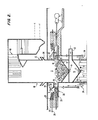
- a combustion chamber 10 has two-stage combustion areas.
- Initial combustion stage 11 is formed by furnace wall 12, lined in a conventional manner and a downwardly-sloped wood support structure, such as a conventional water cooled grate 13.
- a downwardly-sloped wood support structure such as a conventional water cooled grate 13.
- the sloped grate or support structure will vary from a steep incline to a flat grate as is necessary to maintain a relatively even fuel charge depth.
- Substantially whole trees 4 are fed onto grate 13 to form a bed of combustion material burned in initial combustion stage 11. The burning of the bed of trees produces gases which are subsequently burned above the bed of trees at a higher temperature than the burning trees.
- a central opening 14 is formed at the bottom of grate 13 and small char created by combustion of whole trees in initial combustion stage 11 falls through central opening 14 and openings in grate 13 into a second combustion stage 15.
- Second combustion stage 15 is formed by a portion of furnace wall 12 and a downwardly sloped bottom wall 16.
- a central opening 17 at the centre of bottom wall 16 is connected with an ash discharge 18. Char and ash which fall from the central opening 14 burn in second combustion stage 15 and unburned ash is collected at the centre of bottom wall 16. Ash is then taken to the outside of the furnace through central opening 17 and ash discharge 18 for disposal.
- An under fire or primary air inlet 33 is installed in furnace wall 12 of second combustion stage 15 beneath water cooled grate 13 of initial combustion stage 11. Air at approximately 650°F during typical operation is suppled in the horizontal direction through the air inlet 33.
- the air supplied through inlet 33 controls the temperature at which the bed of trees 4 is supported on grate 13 burns. By raising or lowering the flow rate and/or secondarily the temperature of the air the combustion rate of the bed of trees 4 can be raised or lowered.
- the bed of trees 4 is at least three feet high above the bottom grate 13 and preferably at least 6 feet high.
- a pair of over fire or secondary air inlets 34 are also installed symmetrically in furnace wall 12 above initial combustion stage 11.
- Air controlled up to approximately 650°F during typical operation is supplied into initial combustion stage 11 in a movable downwardly slanted direction so that air is effectively mixed with other gases and supplied to the area above the wood bed to control the temperature at which the released gases burn.
- the flow rate and temperature of the air supplied through inlets 33 and 34 is controlled in a conventional manner.
- the temperature of burning fuel in initial combustion stage 11 is around 2000°F and the temperature of the burning gases is preferably around 2600°F.
- a pair of tree charge openings 19 are symmetrically formed in furnace wall 12 at the area of initial combustion stage 11 to feed substantially whole trees into the furnace.
- Each tree charge opening 19 has a gate 20 which opens and closes tree charge opening 19.
- the motion of gate 20 is operated by a gate lifter 21, which comprises, respectively crank 22 and rod 23 which in turn are connected to drive means 24. As drive means 24 are actuated, gate lifters 21 move gates 20 upward and downward.
- Substantially whole trees are carried by drag conveyors 5 from drying buildings 2 and 3 to the furnace in the vicinity of each of tree charge openings 19.
- Conveyor 5 brings whole trees 4 to the furnace at a level higher than tree charge opening 19.
- a charge pit feeder 25 removes whole trees from drag conveyor 5.
- Charge pit feeder 25 has an extendable rod 26 and a plate portion 27 by which whole trees on conveyor 5 are pushed in the horizontal direction transverse to the moving direction of conveyor 5 so that whole trees drop off the conveyor into a charge pit 28 formed adjacent to tree charge opening 19.
- a charge pit 28 is located on each of the two opposite sides of the furnace. One side of charge pit 28 is defined by gate 20 and the other side is defined by a terminal plate of a ram feeder 29.
- the upper opening of charge pit 28 is a tree delivery inlet 30 which has a lid 31.
- Lid 31 is rotatably supported by a horizontally extended portion of furnace wall 12 defining tree charge opening 19.
- Tree delivery inlet 30 is opened or closed by an operating actuator 32 attached to lid 31.
- tree delivery inlet 30 When whole trees 4 are fed into charge pit 28 from conveyor 5, tree delivery inlet 30 is open but gate 20 is closed and ram feeder 29 is at the most recessed position from the tree charge opening 19. After inlet charge pit 30 is filled with substantially whole trees 4, tree delivery inlet 30 is closed, gate 20 is opened and ram feeder 29 is actuated to push the whole trees from charge pit 28 into initial combustion stage 11 through tree charge opening 19. Thus, whole trees are delivered from charge pit 28 to the furnace.
- Whole trees 4 are supplied into the furnace alternately from a tree charge opening on each side of the furnace so that the whole area of initial combustion stage 11 is evenly used for combustion. Any conventional mechanism can be used to initiate the combustion of the trees. Also, once combustion has started, the already burning trees function as the mechanism for initiating the combustion of trees fed into the furnace.
- Both sections 40 are installed above combustion chamber 10 so that the thermal energy created by the combustion of the substantially whole trees, particularly the combustion of the gases produced during gasification of the trees, efficiently produces steam. Steam thus produced is led to the power generators, not shown in Figure 2. Power generators convert thermal energy of the steam into electrical energy. Details of boiler sections and power generators are known in the prior art and not described here. Other systems of converting thermal energy to electrical energy could also be used.
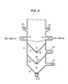
- Figure 2 has two combustion stages i.e. initial combustion stage 11 and second combustion stage 15, it is possible to have three combustion stages.
- Figure 3 illustrates the conceptual relationship of three combustion stages.
- Intermediate combustion stage 50 is added between initial combustion stage 11 and combustion stage 15.
- Intermediate combustions stage 50 is surrounded by furnace wall 12 and has a downwardly sloped grate 51 with a central opening 52.
- Air inlet 53 is also provided in furnace wall 12 horizontally to supply air in intermediate combustion stage 50.
- central opening 14 and the holes in the grate 13 of initial combustion stage 11 are sufficiently large to allow char created from combustion of substantially whole trees to fall into intermediate combustion state 50.
- char is burned and thus creates small char and ash particles which fall through grate 50 and its central opening 52 into combustion stage 15 where these are completely burned into ashes.
- Preferable temperatures of burning fuels in each of the stages are approximately 2000°F in initial combustion stage 11, 1500°F in intermediate stage 50 and 650°F in combustion stage 15. Burning gases above initial combustion stage 11 occurs at approximately 2600°F.
- the whole tree burning power plant reduces fuel cost significantly compared with a conventional processed wood burning power plant, because the present invention eliminates the necessity of processing wood as required in the conventional plant. If the plant of the present invention is sited in a location where long distance transport of whole trees is not necessary, fuel cost can be reduced to less than half of the conventional processed wood burning plant.
- the substantially whole trees of the present invention do not have to be supplied to the furnace at a precisely metered rate, such as processed wood. Rather, a bed of burning substantially whole trees supplies a steady, constant supply of gas and this gas supply can be readily controlled by controlling the temperature of the tree bed combustion so that the trees can be supplied periodically in batches. Also, the larger or higher the bed of trees is made, the lower the temperature at which the bed can be burnt to supply sufficient gas.
- the whole tree burning system of the present invention is also economical in comparison to a coal burning power plant. Because a wood burning power plant virtually eliminates sulphur dioxide emissions typical of fossil power generation, it requires much less plant capital costs and operating costs. Typical flue gas scrubbing equipment, indispensable for a coal burning plant, are not required in a whole tree burning system.
Landscapes
- Engineering & Computer Science (AREA)
- Mechanical Engineering (AREA)
- General Engineering & Computer Science (AREA)
- Environmental & Geological Engineering (AREA)
- Life Sciences & Earth Sciences (AREA)
- Sustainable Development (AREA)
- Sustainable Energy (AREA)
- Wood Science & Technology (AREA)
- Drying Of Solid Materials (AREA)
- Solid-Fuel Combustion (AREA)
- Engine Equipment That Uses Special Cycles (AREA)
- Heat-Pump Type And Storage Water Heaters (AREA)
- Solid Fuels And Fuel-Associated Substances (AREA)
- Control Of Eletrric Generators (AREA)
Priority Applications (1)
| Application Number | Priority Date | Filing Date | Title |
|---|---|---|---|
| AT86309908T ATE82629T1 (de) | 1985-12-20 | 1986-12-18 | Verfahren und anlage zur versorgung eines kraftwerks mit waermeenergie. |
Applications Claiming Priority (2)
| Application Number | Priority Date | Filing Date | Title |
|---|---|---|---|
| US06/811,413 US4706645A (en) | 1985-12-20 | 1985-12-20 | Method and system to provide thermal power for a power plant |
| US811413 | 2001-03-20 |
Publications (3)
| Publication Number | Publication Date |
|---|---|
| EP0228255A2 true EP0228255A2 (fr) | 1987-07-08 |
| EP0228255A3 EP0228255A3 (en) | 1989-01-25 |
| EP0228255B1 EP0228255B1 (fr) | 1992-11-19 |
Family
ID=25206487
Family Applications (1)
| Application Number | Title | Priority Date | Filing Date |
|---|---|---|---|
| EP86309908A Expired EP0228255B1 (fr) | 1985-12-20 | 1986-12-18 | Procédé et installation pour fournir de l'énergie thermique à une centrale électrique |
Country Status (9)
| Country | Link |
|---|---|
| US (1) | US4706645A (fr) |
| EP (1) | EP0228255B1 (fr) |
| JP (1) | JPH0718533B2 (fr) |
| AT (1) | ATE82629T1 (fr) |
| CA (1) | CA1281603C (fr) |
| DE (1) | DE3687144T2 (fr) |
| ES (1) | ES2036527T3 (fr) |
| GR (1) | GR3006557T3 (fr) |
| IN (1) | IN168882B (fr) |
Cited By (3)
| Publication number | Priority date | Publication date | Assignee | Title |
|---|---|---|---|---|
| WO1994018502A1 (fr) * | 1993-02-12 | 1994-08-18 | Ostlie L David | Grille de refroidissement a tubes empiles et systeme thermique d'une centrale electrique |
| DE102007011783A1 (de) * | 2007-03-12 | 2008-09-18 | Conpower Energieanlagen Gmbh & Co Kg. | Verfahren zum Betrieb einer Biomasse-Energieanlage |
| US11427325B2 (en) * | 2017-12-21 | 2022-08-30 | Adient Aerospace, Llc | Table apparatus |
Families Citing this family (6)
| Publication number | Priority date | Publication date | Assignee | Title |
|---|---|---|---|---|
| US4928606A (en) * | 1988-01-13 | 1990-05-29 | Air Products And Chemicals, Inc. | Combustion of low B.T.U./high moisture content fuels |
| DE10240549A1 (de) | 2001-08-31 | 2003-04-10 | Werner Boos | Heizkessel für die Verbrennung von festem Brennstoff |
| US10015931B2 (en) * | 2012-12-28 | 2018-07-10 | Elwha Llc | Production of electricity from plants |
| US10015971B2 (en) | 2012-12-28 | 2018-07-10 | Elwha Llc | Articles and methods for administering CO2 into plants |
| US10017392B2 (en) | 2012-12-28 | 2018-07-10 | Elwha Llc | Articles and methods for administering CO2 into plants |
| JP6558687B2 (ja) * | 2015-01-07 | 2019-08-14 | レッツ株式会社 | 丸太燃料用の燃焼装置、丸太燃料用のボイラーシステム、丸太燃料を用いた燃焼ガスの供給方法、及び丸太燃料を用いた地域内給電システム |
Family Cites Families (12)
| Publication number | Priority date | Publication date | Assignee | Title |
|---|---|---|---|---|
| US408559A (en) * | 1889-08-06 | Henry w | ||
| US2029576A (en) * | 1933-05-20 | 1936-02-04 | American Lurgi Corp | Apparatus for burning low-grade fuels, especially refuse |
| FR821443A (fr) * | 1936-12-07 | 1937-12-04 | Lehmann & Cie | Chaudière à feu continu à bois |
| DE1088177B (de) * | 1956-12-20 | 1960-09-01 | Erika Hingst Geb Buchholz | Schraegrostfeuerung mit feststehenden, gegeneinander geneigten Rosten |
| US3855950A (en) * | 1973-10-10 | 1974-12-24 | Consumat Syst Inc | Automatic loading and ash removal system for incinerators |
| US4372286A (en) * | 1978-10-06 | 1983-02-08 | Baker Arthur L | Wood burning stove |
| US4646713A (en) * | 1979-01-26 | 1987-03-03 | Honigsbaum Richard F | Smoke-incinerating woodstove |
| US4474010A (en) * | 1980-02-15 | 1984-10-02 | Sumitomo Semento Kabushiki Kaisha | Method of recovering exhaust gas from boiler in electrical power generating device using combustible material as fuel and apparatus for performing such method |
| JPS5911201U (ja) * | 1982-07-12 | 1984-01-24 | 株式会社セキノ工場 | スト−ブ |
| US4502462A (en) * | 1982-11-12 | 1985-03-05 | Brent Lawrence | Wood stove |
| US4517903A (en) * | 1983-06-01 | 1985-05-21 | Hunter Enterprises Orillia Limited | Solid fuel furnace |
| JPS608403A (ja) * | 1983-06-29 | 1985-01-17 | Ishikawajima Harima Heavy Ind Co Ltd | タ−ビン過回転制限装置 |
-
1985
- 1985-12-20 US US06/811,413 patent/US4706645A/en not_active Expired - Lifetime
-
1986
- 1986-10-29 IN IN850/MAS/86A patent/IN168882B/en unknown
- 1986-12-17 JP JP61301128A patent/JPH0718533B2/ja not_active Expired - Lifetime
- 1986-12-18 ES ES198686309908T patent/ES2036527T3/es not_active Expired - Lifetime
- 1986-12-18 EP EP86309908A patent/EP0228255B1/fr not_active Expired
- 1986-12-18 CA CA000525767A patent/CA1281603C/fr not_active Expired
- 1986-12-18 AT AT86309908T patent/ATE82629T1/de not_active IP Right Cessation
- 1986-12-18 DE DE8686309908T patent/DE3687144T2/de not_active Expired - Lifetime
-
1992
- 1992-12-16 GR GR920402931T patent/GR3006557T3/el unknown
Cited By (5)
| Publication number | Priority date | Publication date | Assignee | Title |
|---|---|---|---|---|
| WO1994018502A1 (fr) * | 1993-02-12 | 1994-08-18 | Ostlie L David | Grille de refroidissement a tubes empiles et systeme thermique d'une centrale electrique |
| US5381741A (en) * | 1993-02-12 | 1995-01-17 | Ostlie; L. David | Stacked cooling grate and system for providing thermal power for a power plant |
| DE102007011783A1 (de) * | 2007-03-12 | 2008-09-18 | Conpower Energieanlagen Gmbh & Co Kg. | Verfahren zum Betrieb einer Biomasse-Energieanlage |
| DE102007011783B4 (de) * | 2007-03-12 | 2009-03-26 | Conpower Energieanlagen Gmbh & Co Kg. | Verfahren zum Betrieb einer Biomasse-Energieanlage |
| US11427325B2 (en) * | 2017-12-21 | 2022-08-30 | Adient Aerospace, Llc | Table apparatus |
Also Published As
| Publication number | Publication date |
|---|---|
| DE3687144T2 (de) | 1993-04-01 |
| ES2036527T3 (es) | 1993-06-01 |
| US4706645A (en) | 1987-11-17 |
| EP0228255B1 (fr) | 1992-11-19 |
| DE3687144D1 (de) | 1992-12-24 |
| JPH0718533B2 (ja) | 1995-03-06 |
| ATE82629T1 (de) | 1992-12-15 |
| JPS62175504A (ja) | 1987-08-01 |
| IN168882B (fr) | 1991-07-06 |
| GR3006557T3 (fr) | 1993-06-30 |
| EP0228255A3 (en) | 1989-01-25 |
| CA1281603C (fr) | 1991-03-19 |
Similar Documents
| Publication | Publication Date | Title |
|---|---|---|
| US4882903A (en) | Combined cycle waste-to-energy plant | |
| US10364985B2 (en) | Bio-fuel furnace | |
| US20100089295A1 (en) | Continuously-Fed Non-Densified Biomass Combustion System | |
| US5161471A (en) | Apparatus for reburning ash material of a previously burned primary fuel | |
| EP0682764B1 (fr) | Grille de refroidissement a tubes empiles et systeme thermique d'une centrale electrique | |
| US4706645A (en) | Method and system to provide thermal power for a power plant | |
| CN113310054B (zh) | 一种生物质辅助热解的垃圾热解装置 | |
| KR102169127B1 (ko) | 바이콘형 폐기물 압축 및 분쇄 장치 및 폐기물 예비 건조장치가 구비된 스토커식 소각로 | |
| CN114383136A (zh) | 一种垃圾热解气化炉 | |
| CN108506938A (zh) | 一种燃煤锅炉分级焚烧含生物质的废弃物的方法和系统 | |
| CA3158827C (fr) | Appareil et methode de chaudiere a balle | |
| CA1226173A (fr) | Incinerateurs, et leurs gazeificateurs et bruleurs | |
| CN106224970B (zh) | 机械炉排式垃圾气化焚烧系统和倒锥型内腔燃烧室 | |
| CN211011384U (zh) | 一种处理生活垃圾的清洁高温共燃炉 | |
| CN209655336U (zh) | 一种生物颗粒与燃煤耦合发电系统 | |
| CN100381756C (zh) | 高温焚烧垃圾的方法及其设备 | |
| EP4092320B1 (fr) | Chaudière à balles | |
| CN1102247A (zh) | 垃圾焚烧和热量运用设备 | |
| CN108506942A (zh) | 一种燃煤锅炉焚烧含生物质的废弃物的方法和系统 | |
| CN120403233A (zh) | 一种用于粮食烘干的生物质自驱动热解供热方法及装备 | |
| CN106287734A (zh) | 机械炉排式垃圾气化焚烧系统和合成气参数反馈燃烧装置 | |
| CN2240249Y (zh) | 提供热烟气的燃烧装置 | |
| CN106224968A (zh) | 机械炉排式垃圾气化焚烧系统和湍动燃烧装置 | |
| Graham | Biomass fuels for steam generation | |
| CN114686250A (zh) | 一种用于生物质碳化的回收装置、设备及方法 |
Legal Events
| Date | Code | Title | Description |
|---|---|---|---|
| PUAI | Public reference made under article 153(3) epc to a published international application that has entered the european phase |
Free format text: ORIGINAL CODE: 0009012 |
|
| AK | Designated contracting states |
Kind code of ref document: A2 Designated state(s): AT BE CH DE ES FR GB GR IT LI LU NL SE |
|
| PUAL | Search report despatched |
Free format text: ORIGINAL CODE: 0009013 |
|
| AK | Designated contracting states |
Kind code of ref document: A3 Designated state(s): AT BE CH DE ES FR GB GR IT LI LU NL SE |
|
| RAP1 | Party data changed (applicant data changed or rights of an application transferred) |
Owner name: OSTLIE, DAVID L. |
|
| DIN1 | Information on inventor provided before grant (deleted) | ||
| RIN1 | Information on inventor provided before grant (corrected) |
Inventor name: OSTLIE, DAVID L. |
|
| 17P | Request for examination filed |
Effective date: 19890721 |
|
| 17Q | First examination report despatched |
Effective date: 19900108 |
|
| GRAA | (expected) grant |
Free format text: ORIGINAL CODE: 0009210 |
|
| AK | Designated contracting states |
Kind code of ref document: B1 Designated state(s): AT BE CH DE ES FR GB GR IT LI LU NL SE |
|
| REF | Corresponds to: |
Ref document number: 82629 Country of ref document: AT Date of ref document: 19921215 Kind code of ref document: T |
|
| REF | Corresponds to: |
Ref document number: 3687144 Country of ref document: DE Date of ref document: 19921224 |
|
| ET | Fr: translation filed | ||
| ITF | It: translation for a ep patent filed | ||
| RAP2 | Party data changed (patent owner data changed or rights of a patent transferred) |
Owner name: OSTLIE, L DAVID |
|
| REG | Reference to a national code |
Ref country code: GR Ref legal event code: FG4A Free format text: 3006557 |
|
| REG | Reference to a national code |
Ref country code: ES Ref legal event code: FG2A Ref document number: 2036527 Country of ref document: ES Kind code of ref document: T3 |
|
| PLBE | No opposition filed within time limit |
Free format text: ORIGINAL CODE: 0009261 |
|
| STAA | Information on the status of an ep patent application or granted ep patent |
Free format text: STATUS: NO OPPOSITION FILED WITHIN TIME LIMIT |
|
| 26N | No opposition filed | ||
| EPTA | Lu: last paid annual fee | ||
| EAL | Se: european patent in force in sweden |
Ref document number: 86309908.1 |
|
| PGFP | Annual fee paid to national office [announced via postgrant information from national office to epo] |
Ref country code: NL Payment date: 19980914 Year of fee payment: 13 |
|
| PGFP | Annual fee paid to national office [announced via postgrant information from national office to epo] |
Ref country code: GR Payment date: 19981022 Year of fee payment: 13 |
|
| PGFP | Annual fee paid to national office [announced via postgrant information from national office to epo] |
Ref country code: AT Payment date: 19981105 Year of fee payment: 13 |
|
| PGFP | Annual fee paid to national office [announced via postgrant information from national office to epo] |
Ref country code: CH Payment date: 19981218 Year of fee payment: 13 |
|
| PGFP | Annual fee paid to national office [announced via postgrant information from national office to epo] |
Ref country code: BE Payment date: 19990111 Year of fee payment: 13 |
|
| PG25 | Lapsed in a contracting state [announced via postgrant information from national office to epo] |
Ref country code: AT Free format text: LAPSE BECAUSE OF NON-PAYMENT OF DUE FEES Effective date: 19991218 |
|
| PG25 | Lapsed in a contracting state [announced via postgrant information from national office to epo] |
Ref country code: SE Free format text: LAPSE BECAUSE OF NON-PAYMENT OF DUE FEES Effective date: 19991219 |
|
| PG25 | Lapsed in a contracting state [announced via postgrant information from national office to epo] |
Ref country code: LI Free format text: LAPSE BECAUSE OF NON-PAYMENT OF DUE FEES Effective date: 19991231 Ref country code: GR Free format text: LAPSE BECAUSE OF NON-PAYMENT OF DUE FEES Effective date: 19991231 Ref country code: CH Free format text: LAPSE BECAUSE OF NON-PAYMENT OF DUE FEES Effective date: 19991231 Ref country code: BE Free format text: LAPSE BECAUSE OF NON-PAYMENT OF DUE FEES Effective date: 19991231 |
|
| BERE | Be: lapsed |
Owner name: OSTLIE DAVID L. Effective date: 19991231 |
|
| PG25 | Lapsed in a contracting state [announced via postgrant information from national office to epo] |
Ref country code: NL Free format text: LAPSE BECAUSE OF NON-PAYMENT OF DUE FEES Effective date: 20000701 |
|
| EUG | Se: european patent has lapsed |
Ref document number: 86309908.1 |
|
| NLV4 | Nl: lapsed or anulled due to non-payment of the annual fee |
Effective date: 20000701 |
|
| REG | Reference to a national code |
Ref country code: FR Ref legal event code: ST |
|
| PGFP | Annual fee paid to national office [announced via postgrant information from national office to epo] |
Ref country code: SE Payment date: 20001222 Year of fee payment: 15 |
|
| REG | Reference to a national code |
Ref country code: FR Ref legal event code: RN |
|
| REG | Reference to a national code |
Ref country code: FR Ref legal event code: FC |
|
| PGFP | Annual fee paid to national office [announced via postgrant information from national office to epo] |
Ref country code: DE Payment date: 20010227 Year of fee payment: 15 |
|
| NLXE | Nl: other communications concerning ep-patents (part 3 heading xe) |
Free format text: A REQUEST FOR RESTORATION TO THE PRIOR STATE (ART. 17A OF THE DUTCH PATENT ACT) HAS BEEN FILED ON 28.05.2001. |
|
| PGFP | Annual fee paid to national office [announced via postgrant information from national office to epo] |
Ref country code: LU Payment date: 20011212 Year of fee payment: 15 |
|
| REG | Reference to a national code |
Ref country code: GB Ref legal event code: IF02 |
|
| PGFP | Annual fee paid to national office [announced via postgrant information from national office to epo] |
Ref country code: FR Payment date: 20020523 Year of fee payment: 16 |
|
| PG25 | Lapsed in a contracting state [announced via postgrant information from national office to epo] |
Ref country code: LU Free format text: LAPSE BECAUSE OF NON-PAYMENT OF DUE FEES Effective date: 20021218 |
|
| PG25 | Lapsed in a contracting state [announced via postgrant information from national office to epo] |
Ref country code: FR Free format text: LAPSE BECAUSE OF NON-PAYMENT OF DUE FEES Effective date: 20030901 |
|
| REG | Reference to a national code |
Ref country code: FR Ref legal event code: ST |
|
| PGFP | Annual fee paid to national office [announced via postgrant information from national office to epo] |
Ref country code: GB Payment date: 20031217 Year of fee payment: 18 |
|
| PGFP | Annual fee paid to national office [announced via postgrant information from national office to epo] |
Ref country code: ES Payment date: 20040123 Year of fee payment: 18 |
|
| PG25 | Lapsed in a contracting state [announced via postgrant information from national office to epo] |
Ref country code: GB Free format text: LAPSE BECAUSE OF NON-PAYMENT OF DUE FEES Effective date: 20041218 |
|
| PG25 | Lapsed in a contracting state [announced via postgrant information from national office to epo] |
Ref country code: ES Free format text: LAPSE BECAUSE OF NON-PAYMENT OF DUE FEES Effective date: 20041220 |
|
| GBPC | Gb: european patent ceased through non-payment of renewal fee |
Effective date: 20041218 |
|
| PG25 | Lapsed in a contracting state [announced via postgrant information from national office to epo] |
Ref country code: IT Free format text: LAPSE BECAUSE OF NON-PAYMENT OF DUE FEES Effective date: 20051218 |
|
| REG | Reference to a national code |
Ref country code: ES Ref legal event code: FD2A Effective date: 20041220 |