EP0228258A1 - Une filière pour extruder des corps à structure en nid d'abeilles - Google Patents
Une filière pour extruder des corps à structure en nid d'abeilles Download PDFInfo
- Publication number
- EP0228258A1 EP0228258A1 EP86309926A EP86309926A EP0228258A1 EP 0228258 A1 EP0228258 A1 EP 0228258A1 EP 86309926 A EP86309926 A EP 86309926A EP 86309926 A EP86309926 A EP 86309926A EP 0228258 A1 EP0228258 A1 EP 0228258A1
- Authority
- EP
- European Patent Office
- Prior art keywords
- body supply
- supply holes
- inner peripheral
- extrusion die
- peripheral surface
- Prior art date
- Legal status (The legal status is an assumption and is not a legal conclusion. Google has not performed a legal analysis and makes no representation as to the accuracy of the status listed.)
- Granted
Links
- 238000001125 extrusion Methods 0.000 claims abstract description 49
- 239000000919 ceramic Substances 0.000 claims abstract description 11
- 230000002093 peripheral effect Effects 0.000 claims description 45
- 241000264877 Hippospongia communis Species 0.000 claims description 28
- 238000000034 method Methods 0.000 claims description 18
- 238000003754 machining Methods 0.000 claims description 4
- 235000019592 roughness Nutrition 0.000 abstract 1
- 238000004519 manufacturing process Methods 0.000 description 8
- 230000003746 surface roughness Effects 0.000 description 6
- 229910010293 ceramic material Inorganic materials 0.000 description 2
- 229910000831 Steel Inorganic materials 0.000 description 1
- PNEYBMLMFCGWSK-UHFFFAOYSA-N aluminium oxide Inorganic materials [O-2].[O-2].[O-2].[Al+3].[Al+3] PNEYBMLMFCGWSK-UHFFFAOYSA-N 0.000 description 1
- 239000000969 carrier Substances 0.000 description 1
- 239000003054 catalyst Substances 0.000 description 1
- 238000002485 combustion reaction Methods 0.000 description 1
- 239000000470 constituent Substances 0.000 description 1
- 229910052878 cordierite Inorganic materials 0.000 description 1
- JSKIRARMQDRGJZ-UHFFFAOYSA-N dimagnesium dioxido-bis[(1-oxido-3-oxo-2,4,6,8,9-pentaoxa-1,3-disila-5,7-dialuminabicyclo[3.3.1]nonan-7-yl)oxy]silane Chemical compound [Mg++].[Mg++].[O-][Si]([O-])(O[Al]1O[Al]2O[Si](=O)O[Si]([O-])(O1)O2)O[Al]1O[Al]2O[Si](=O)O[Si]([O-])(O1)O2 JSKIRARMQDRGJZ-UHFFFAOYSA-N 0.000 description 1
- KZHJGOXRZJKJNY-UHFFFAOYSA-N dioxosilane;oxo(oxoalumanyloxy)alumane Chemical compound O=[Si]=O.O=[Si]=O.O=[Al]O[Al]=O.O=[Al]O[Al]=O.O=[Al]O[Al]=O KZHJGOXRZJKJNY-UHFFFAOYSA-N 0.000 description 1
- 230000000694 effects Effects 0.000 description 1
- 239000007789 gas Substances 0.000 description 1
- 239000000463 material Substances 0.000 description 1
- 229910052751 metal Inorganic materials 0.000 description 1
- 239000002184 metal Substances 0.000 description 1
- 150000002739 metals Chemical class 0.000 description 1
- 229910052863 mullite Inorganic materials 0.000 description 1
- 235000012149 noodles Nutrition 0.000 description 1
- HBMJWWWQQXIZIP-UHFFFAOYSA-N silicon carbide Chemical compound [Si+]#[C-] HBMJWWWQQXIZIP-UHFFFAOYSA-N 0.000 description 1
- 229910010271 silicon carbide Inorganic materials 0.000 description 1
- 239000010959 steel Substances 0.000 description 1
Images

Classifications
-
- B—PERFORMING OPERATIONS; TRANSPORTING
- B28—WORKING CEMENT, CLAY, OR STONE
- B28B—SHAPING CLAY OR OTHER CERAMIC COMPOSITIONS; SHAPING SLAG; SHAPING MIXTURES CONTAINING CEMENTITIOUS MATERIAL, e.g. PLASTER
- B28B3/00—Producing shaped articles from the material by using presses; Presses specially adapted therefor
- B28B3/20—Producing shaped articles from the material by using presses; Presses specially adapted therefor wherein the material is extruded
- B28B3/26—Extrusion dies
- B28B3/269—For multi-channeled structures, e.g. honeycomb structures
Definitions
- the present invention relates to an extrusion die and a process for producing such an extrusion die. More particularly, the present invention relates to a honeycomb-shaped extrusion die adapted to extrude ceramic honeycomb structural bodies comprising body discharge channels and a plurality of independent body supply holes communicating with the body discharge channels as well as a process for producing the same.
- Ceramic honeycomb structural bodies are used as catalyst carriers for purifying exhaust gases from internal combustion engines, as fine particle-capturing filters, as heat retainers, etc.
- Such ceramic honeycomb structural bodies are constituted by ceramic materials such as cordierite, alumina, silicon-carbide, mullite etc. There are known processes for producing the bodies by extruding the ceramic material with use of an extrusion die.
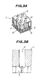
- the conventional example (extrusion die 1) shown in Fig. 3(A) comprises a plurality of body supply holes 2 through which a body fed under pressure by a body feeder (not shown) is passed, body stay zones 3 communicating with the body supply holes 2, and body discharge channels 4 having an arrangement corresponding to that of ceramic honeycomb structural bodies to be extruded (hereafter briefly referred to as "honeycomb structural bodies").
- Fig. 3(B) is a partial sectional view of another conventional example.
- This example of Fig. 3(B) comprises a plurality of body supply holes 2 and body discharge channels 4 directly communicating with the body supply holes 2.
- the body supply holes of the above conventional extrusion dies have a straight cylindrical shape. They are bored by drills.
- hard metals such as die steel are used as the extrusion dies, such boring has poor workability.
- a chip produced in the boring enters between the drill and workpiece resulting in roughness of the inner peripheral surface of the body supply hole.
- the surface roughness differs among the inner peripheral surfaces of the respective body supply holes.
- uniformalized flow resistance of a plurality of the body supply holes is an important requirement for production of high quality honeycomb structural bodies.
- the flow resistance depends upon the roughness of the inner peripheral surface of the body supply holes.
- the surface roughness very much influences the flow resistance because the body supply holes are relatively small. Therefore, there arises large variations in flow resistance among the body supply holes of the conventional extrusion die. As a result, there exists an undesirable problem that it is difficult to manufacture honeycomb structural bodies of a high quality.
- the roughness of the inner peripheral surface is improved by honing or reaming after the body supply holes are bored.
- the depth of the body supply holes is great, the surface roughness becomes more non-uniform.
- a die is divided into two die units, and slits and supply holes are machined in one of the die units, while only supply holes are formed in the other die unit. Then, they are bonded together.
- a manufacturing cost of the extrusion dies rises due to increased working steps.
- the present invention aims to solve the abovementioned problems, and to provide extrusion dies in which the flow resistance of a plurality of body supply holes is made more uniform or substantially uniform by a simple measure.
- an extrusion die for extruding ceramic honeycomb structural bodies, said extrusion die comprising body discharge channels having a desired honeycomb arrangement and independent body supply holes communicating with the body discharge channels, wherein the body supply holes are so designed that each of them may have a plurality of inner peripheral surface zones of different inner dimensions and said inner peripheral surface zones may be coaxially arranged.
- an extrusion die adapted to extrude ceramic honeycomb structural bodies, said extrusion dies comprising body discharge channels having a desired honeycomb arrangement and a plurality of independent body supply holes communicating with the body discharge channels, said process comprising the steps: of boring said body supply holes such that each of the body supply holes may have a plurality of coaxial inner peripheral surface zones of different inner dimensions, and said body supply holes may an uniform flow resistance, and forming said body discharge channels which communicate with the body supply holes and have honeycomb arrangement corresponding to the ceramic honeycomb structural body to be extruded.
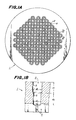
- Figs. 1(A) and 1(B) show the extrusion die 1, having body supply holes 2, body discharge channels 4.
- Each body supply hole 2 has a first inner peripheral surface portion 5 and a second inner peripheral surface portion 6.
- each of the body supply holes is constituted by a plurality of coaxial inner peripheral surface zones having different inner dimensions, that is, in the embodiment of Figs. 1(A) and 1(B), a first inner peripheral surface 5 having an inner diameter ⁇ 1 and a second inner peripheral surface 6 having an inner diameter ⁇ 2.
- the body supply hole 2 is formed by first forming the first inner peripheral surface having the inner diameter of ⁇ 1 to a depth of d1 by means of a drill and then forming the second inner peripheral surface 6 having the inner diameter of ⁇ 2 by means of another drill over a depth d2 so as to make the supply hole 2 communicate with the body discharge channels 4.
- the extrusion die according to the present invention is provided with the body supply holes each having a plurality of inner peripheral surface zones of different inner dimensions. Therefore, as compared with conventional extrusion dies having straight-shaped body supply holes, the flow resistance of the body supply holes in the extrusion die according to the present invention is far larger. Accordingly, even when some difference exists in roughness among the inner peripheral surfaces of the body supply holes in the extrusion die according to the present invention, the influence of variations in the surface roughness upon the flow resistance can be almost ignored. That is, with the present invention, since the flow resistance of the body supply holes can be made substantially uniform, honeycomb structural bodies of a high quality can be manufactured.
- the first inner peripheral surface 5 and the second inner peripheral surface 6 constituting the body supply hole 2 are shown so formed that their depths d1 and d2 are substantially equal. But it is preferable that the depths d1 and d2 are appropriately selected depending upon the shape, the cell density and the outer size of the honeycomb structural body. For instance, when the honeycomb structural body has a high cell density and/or a large outer size, d1 is preferably smaller than d2 so as to assure the strength of the extrusion die.
- the conventional extrusion dies are produced by boring a plurality of body supply holes in a die material of a desired shape from one working surface thereof by a drill, and forming the body discharge channels in a desired honeycomb arrangement from the other working surface to communicate with the body supply holes by a well-known discharge working method or a thin blade cutter.
- a limitation is imposed upon the machining depth [(d1+d2) shown in Fig. 1(B)] in relation to the diameter of the drills used. If this limitation is exceeded, it becomes difficult to remove cut chips.
- the roughness of the inner peripheral surface of the body supply holes becomes coarse and non-uniform.
- the body supply holes deviate on the body discharge side to make the conformity between the body supply holes and the body discharge channels poorer.
- the production process according to the present invention can avoid the above-mentioned problems. That is, as shown in Fig. 1(B), holes of an inner diameter of ⁇ 1 (the first inner peripheral surface 5) are bored at a specific depth of d1 by a drill. Then, holes having an inner diameter of ⁇ 2 ( ⁇ 2 ⁇ 1) (the second inner peripheral surface 6) are similarly drilled coaxially with the central axis of the first inner peripheral surface 5, thereby forming body supply holes 2. Thereafter, the desired extrusion die is produced by forming body discharge channels 4 having a desired honeycomb arrangement according to the discharge working process or a thin blade cutter to communicate with the body supply holes.
- the body supply holes 2 are bored in two separate stages of forming the holes of the depth of d1 and the depth of d2, chips are easily removed.
- body supply holes 2 which are relatively free from occurrence of flaws at the inner peripheral surfaces due to the chips can be stably obtained.
- the body supply hole is constituted by the first and second inner peripheral surfaces 5 and 6 having the different inner dimensions, the intrinsic flow resistance becomes larger.
- the influence of the roughness of the inner peripheral surfaces (the first and second inner peripheral surfaces 5 and 6 in the embodiment shown in Figs. 1(A) and 1(B)) of the body supply holes upon the flow resistance can be ignored.
- a extrusion die which has uniformalized flow resistance of its body supply holes 2 and allows the extrusion of the honeycomb structural bodies of high quality can be produced.
- the following production process may be used. That is, preliminary holes smaller than the intended inner dimensions ⁇ 1 and ⁇ 2 are bored, and body discharge channels are machined to communicate with the preliminary holes. Then, the supply holes 2 are fully machined in the above-mentioned way.
- the body discharge channels 4 are not necessarily fully machined in a desired honeycomb arrangement just subsequent to the boring of the preliminary body supply holes, but preliminary body discharge channels which communicate therewith may be formed first. Then, the body discharge channels 4 having the desired honeycomb arrangement are machined after the body supply holes 2 are fully bored.
- the embodiment in Figs. 1(A) and 1(B) includes body supply holes 2 each constituted by the first inner peripheral surface 5 and the second inner peripheral surface 6.
- the body supply holes may be designed to having three or more inner peripheral surface zones of different inner dimensions.
- the body supply holes are of a cylindrical shape, but they may be designed in a shape (for instance, a rectangular section) other than the cylindrical shape.
- the intrinsic flow resistance of the body supply holes is increased by providing a stepped portion or step portions in the inner peripheral surface of each of the body supply holes, so that the influences of the roughness of the inner peripheral surfaces of the body supply holes upon the flow resistance can be substantially ignored.
- the honeycomb structural bodies having a high quality can be extruded by making the flow resistance of the body supply holes formed in the extrusion die uniform.
- a plurality of inner peripheral surface zones of body supply holes 2 are constituted by helical threads 7.
- a plurality of circumferential parallel grooves are formed in the inner peripheral surfaces of the body supply holes 2.
- a recess 9 is formed in the inner peripheral surface of each of the body supply holes 2.
- the extrusion dies illustrated in Figs. 2(B) and 2(C) may be made by bonding techniques (that is, for instance, an extrusion die is formed by bonding a die unit having first holes with another die unit having second holes such that the first and second holes may be axially arrayed)
- the present invention allows manufacturing of the ceramic honeycomb structural bodies of a high quality because the flow resistance of the body supply holes is made uniform while the influence of the roughness of the inner peripheral surfaces of the body supply holes is reduced or avoided. Besides, since a machining step for improving the roughness of the inner peripheral surface of the body supply holes can be omitted, the working steps are simplified and manufacturing cost can be reduced.
Landscapes
- Engineering & Computer Science (AREA)
- Manufacturing & Machinery (AREA)
- Chemical & Material Sciences (AREA)
- Ceramic Engineering (AREA)
- Mechanical Engineering (AREA)
- Press-Shaping Or Shaping Using Conveyers (AREA)
Applications Claiming Priority (2)
| Application Number | Priority Date | Filing Date | Title |
|---|---|---|---|
| JP284571/85 | 1985-12-18 | ||
| JP60284571A JPS62142607A (ja) | 1985-12-18 | 1985-12-18 | 押出ダイスおよびその製造方法 |
Publications (2)
| Publication Number | Publication Date |
|---|---|
| EP0228258A1 true EP0228258A1 (fr) | 1987-07-08 |
| EP0228258B1 EP0228258B1 (fr) | 1989-09-13 |
Family
ID=17680185
Family Applications (1)
| Application Number | Title | Priority Date | Filing Date |
|---|---|---|---|
| EP86309926A Expired EP0228258B1 (fr) | 1985-12-18 | 1986-12-18 | Une filière pour extruder des corps à structure en nid d'abeilles |
Country Status (4)
| Country | Link |
|---|---|
| US (1) | US4883420A (fr) |
| EP (1) | EP0228258B1 (fr) |
| JP (1) | JPS62142607A (fr) |
| DE (1) | DE3665551D1 (fr) |
Cited By (3)
| Publication number | Priority date | Publication date | Assignee | Title |
|---|---|---|---|---|
| WO1999020445A1 (fr) * | 1997-10-17 | 1999-04-29 | Corning Incorporated | Filiere a fentes modifiees |
| US6299813B1 (en) | 1999-09-23 | 2001-10-09 | Corning Incorporated | Modified slot extrusion dies |
| CN102862037A (zh) * | 2012-09-17 | 2013-01-09 | 李少荣 | 一种超大规格高孔密度蜂窝陶瓷模具的制备方法 |
Families Citing this family (10)
| Publication number | Priority date | Publication date | Assignee | Title |
|---|---|---|---|---|
| US5089190A (en) * | 1989-11-13 | 1992-02-18 | Nordson Corporation | Method and apparatus for hollow core extrusion of high viscosity materials |
| US5814164A (en) | 1994-11-09 | 1998-09-29 | American Scientific Materials Technologies L.P. | Thin-walled, monolithic iron oxide structures made from steels, and methods for manufacturing such structures |
| US6045628A (en) * | 1996-04-30 | 2000-04-04 | American Scientific Materials Technologies, L.P. | Thin-walled monolithic metal oxide structures made from metals, and methods for manufacturing such structures |
| US5702659A (en) * | 1995-11-30 | 1997-12-30 | Corning Incorporated | Honeycomb extrusion die and methods |
| US5997720A (en) * | 1997-02-06 | 1999-12-07 | Corning Incorporated | Method for machining extrusion dies |
| US6461562B1 (en) | 1999-02-17 | 2002-10-08 | American Scientific Materials Technologies, Lp | Methods of making sintered metal oxide articles |
| US6520429B1 (en) * | 2000-01-07 | 2003-02-18 | Hideo Suzuki | Multi-tube extruding equipment |
| JP3903733B2 (ja) * | 2001-04-27 | 2007-04-11 | 株式会社デンソー | ハニカム構造体成形用金型 |
| WO2011158914A1 (fr) * | 2010-06-17 | 2011-12-22 | 住友化学株式会社 | Dispositif de moulage par extrusion et procédé de fabrication de corps moulé au moyen du dispositif |
| MX357751B (es) * | 2012-06-04 | 2018-07-23 | Ngk Insulators Ltd | Matriz para formar estructura de panal y metodo para su fabricacion. |
Citations (4)
| Publication number | Priority date | Publication date | Assignee | Title |
|---|---|---|---|---|
| GB1160355A (en) * | 1967-01-26 | 1969-08-06 | Kabel Metallwerke Ghh | An Extrusion Die Assembly. |
| US4384841A (en) * | 1980-10-31 | 1983-05-24 | Nippon Soken, Inc. | Extrusion die for extruding a honeycomb structure |
| EP0083850A2 (fr) * | 1982-01-11 | 1983-07-20 | General Motors Corporation | Méthode de fabrication d'une matrice d'extrusion |
| EP0120716A2 (fr) * | 1983-03-29 | 1984-10-03 | Corning Glass Works | Matrice d'extrusion |
Family Cites Families (15)
| Publication number | Priority date | Publication date | Assignee | Title |
|---|---|---|---|---|
| US3790654A (en) * | 1971-11-09 | 1974-02-05 | Corning Glass Works | Extrusion method for forming thinwalled honeycomb structures |
| US3826603A (en) * | 1972-08-14 | 1974-07-30 | R Wiley | Extrusion die |
| US3859031A (en) * | 1973-05-10 | 1975-01-07 | Du Pont | Spinneret capillary metering plugs |
| JPS5951402B2 (ja) * | 1977-05-04 | 1984-12-13 | 日本碍子株式会社 | ハニカム成型用ダイス |
| NL7706501A (en) * | 1977-06-13 | 1978-12-15 | Gist Brocades Nv | Extruder discharge mouthpiece - which eliminates surface defects and variations in cross=section, for use in extrusion of yeast |
| JPS583802B2 (ja) * | 1979-09-12 | 1983-01-22 | 株式会社日本自動車部品総合研究所 | ハニカム成型用ダイスの製造方法 |
| FR2467067A1 (fr) * | 1979-10-15 | 1981-04-17 | Ceraver | Dispositif pour la fabrication de corps a structure alveolaire par extrusion d'une matiere ceramique, et procede d'obtention dudit dispositif |
| JPS5761592A (en) * | 1980-10-01 | 1982-04-14 | Osaka Shiiring Insatsu Kk | Transfer sheet |
| US4376747A (en) * | 1980-12-11 | 1983-03-15 | Union Carbide Corporation | Process for controlling the cross-sectional structure of mesophase pitch derived fibers |
| JPS5946763A (ja) * | 1982-09-10 | 1984-03-16 | Kureha Chem Ind Co Ltd | 二層構造のモノポーラ型燃料電池用電極基板の製造方法 |
| JPS5953844A (ja) * | 1982-09-22 | 1984-03-28 | Fujitsu Ltd | レジスト膜現像方法 |
| US4457686A (en) * | 1983-03-21 | 1984-07-03 | Ingersol-Rand Company | Pellet extrusion die |
| JPS61220805A (ja) * | 1985-03-28 | 1986-10-01 | 日本碍子株式会社 | セラミツクハニカム構造体の押出ダイス |
| JP3128308B2 (ja) * | 1991-12-20 | 2001-01-29 | 三洋電機株式会社 | マッサージ器 |
| JP3262390B2 (ja) * | 1992-11-25 | 2002-03-04 | 川崎マイクロエレクトロニクス株式会社 | 金属膜の形成方法 |
-
1985
- 1985-12-18 JP JP60284571A patent/JPS62142607A/ja active Granted
-
1986
- 1986-12-18 DE DE8686309926T patent/DE3665551D1/de not_active Expired
- 1986-12-18 EP EP86309926A patent/EP0228258B1/fr not_active Expired
-
1988
- 1988-09-02 US US07/240,446 patent/US4883420A/en not_active Expired - Lifetime
Patent Citations (4)
| Publication number | Priority date | Publication date | Assignee | Title |
|---|---|---|---|---|
| GB1160355A (en) * | 1967-01-26 | 1969-08-06 | Kabel Metallwerke Ghh | An Extrusion Die Assembly. |
| US4384841A (en) * | 1980-10-31 | 1983-05-24 | Nippon Soken, Inc. | Extrusion die for extruding a honeycomb structure |
| EP0083850A2 (fr) * | 1982-01-11 | 1983-07-20 | General Motors Corporation | Méthode de fabrication d'une matrice d'extrusion |
| EP0120716A2 (fr) * | 1983-03-29 | 1984-10-03 | Corning Glass Works | Matrice d'extrusion |
Non-Patent Citations (2)
| Title |
|---|
| SOVIET INVENTIONS ILLUSTRATED, M section, week B 40, November 14, 1979 DERWENT PUBLICATIONS LTD., London, P 51 * |
| SOVIET INVENTIONS ILLUSTRATED, M section, week D 29, August 26, 1981 DERWENT PUBLICATIONS LTD., London, P 51 & SU-A-642 037 (PRILEPSKII) * |
Cited By (4)
| Publication number | Priority date | Publication date | Assignee | Title |
|---|---|---|---|---|
| WO1999020445A1 (fr) * | 1997-10-17 | 1999-04-29 | Corning Incorporated | Filiere a fentes modifiees |
| US6080348A (en) * | 1997-10-17 | 2000-06-27 | Corning Incorporated | Modified slot extrusion die |
| US6299813B1 (en) | 1999-09-23 | 2001-10-09 | Corning Incorporated | Modified slot extrusion dies |
| CN102862037A (zh) * | 2012-09-17 | 2013-01-09 | 李少荣 | 一种超大规格高孔密度蜂窝陶瓷模具的制备方法 |
Also Published As
| Publication number | Publication date |
|---|---|
| JPH0140730B2 (fr) | 1989-08-31 |
| EP0228258B1 (fr) | 1989-09-13 |
| JPS62142607A (ja) | 1987-06-26 |
| DE3665551D1 (en) | 1989-10-19 |
| US4883420A (en) | 1989-11-28 |
Similar Documents
| Publication | Publication Date | Title |
|---|---|---|
| EP0228258B1 (fr) | Une filière pour extruder des corps à structure en nid d'abeilles | |
| EP0083850B1 (fr) | Méthode de fabrication d'une matrice d'extrusion | |
| US5070588A (en) | Process for producing ceramic honeycomb structure extrusion dies | |
| EP1594687B1 (fr) | Corps alveolaire ceramique et procede de fabrication | |
| US6290837B1 (en) | Method for machining slots in molding die | |
| EP0137572B1 (fr) | Extrudeuse pour structure en nid d'abeilles et procédé pour extruder ladite structure | |
| US4687433A (en) | Die for extruding ceramic honeycomb structural bodies | |
| EP0776743B1 (fr) | Matrice d'extrusion pour nid d'abeilles et procédés pour son obtention | |
| JPS583802B2 (ja) | ハニカム成型用ダイスの製造方法 | |
| JP4210446B2 (ja) | ハニカム押出成形用口金及びその製造方法 | |
| US4820146A (en) | Super hard alloy dies for extruding honeycomb structures | |
| JPS6120403B2 (fr) | ||
| US9162302B2 (en) | Manufacturing method of electrode for honeycomb structure forming die | |
| US4653996A (en) | Die for extruding honeycomb structural body | |
| JPS58217308A (ja) | ハニカム構造体押出成形用ダイスの製造方法 | |
| US6317960B1 (en) | Extrusion die and method of forming | |
| US9108260B2 (en) | Manufacturing method of electrode for honeycomb structure forming die | |
| JP3121408B2 (ja) | ハニカム構造体の押出成形用ダイス及びその製造方法 | |
| JP2008188701A (ja) | ハニカム体成形用金型製造用ドリル及びそれを用いたハニカム体成形用金型の製造方法。 | |
| JPH0219730B2 (fr) | ||
| JPH05131427A (ja) | ハニカム構造体の押出成形用ダイス | |
| JP2002079510A (ja) | セラミックハニカム押出成形用口金 | |
| SU1085704A2 (ru) | Способ изготовлени режущего инструмента | |
| JPH06128606A (ja) | 螺旋状穴付超硬丸棒の製造方法 | |
| JPS5838084B2 (ja) | ハニカム成型用ダイスの製造方法 |
Legal Events
| Date | Code | Title | Description |
|---|---|---|---|
| PUAI | Public reference made under article 153(3) epc to a published international application that has entered the european phase |
Free format text: ORIGINAL CODE: 0009012 |
|
| 17P | Request for examination filed |
Effective date: 19870203 |
|
| AK | Designated contracting states |
Kind code of ref document: A1 Designated state(s): BE DE FR GB SE |
|
| 17Q | First examination report despatched |
Effective date: 19880822 |
|
| GRAA | (expected) grant |
Free format text: ORIGINAL CODE: 0009210 |
|
| AK | Designated contracting states |
Kind code of ref document: B1 Designated state(s): BE DE FR GB SE |
|
| REF | Corresponds to: |
Ref document number: 3665551 Country of ref document: DE Date of ref document: 19891019 |
|
| ET | Fr: translation filed | ||
| PLBE | No opposition filed within time limit |
Free format text: ORIGINAL CODE: 0009261 |
|
| STAA | Information on the status of an ep patent application or granted ep patent |
Free format text: STATUS: NO OPPOSITION FILED WITHIN TIME LIMIT |
|
| 26N | No opposition filed | ||
| PGFP | Annual fee paid to national office [announced via postgrant information from national office to epo] |
Ref country code: GB Payment date: 19941208 Year of fee payment: 9 Ref country code: FR Payment date: 19941208 Year of fee payment: 9 |
|
| PGFP | Annual fee paid to national office [announced via postgrant information from national office to epo] |
Ref country code: SE Payment date: 19941212 Year of fee payment: 9 |
|
| EAL | Se: european patent in force in sweden |
Ref document number: 86309926.3 |
|
| PG25 | Lapsed in a contracting state [announced via postgrant information from national office to epo] |
Ref country code: GB Effective date: 19951218 |
|
| PG25 | Lapsed in a contracting state [announced via postgrant information from national office to epo] |
Ref country code: SE Effective date: 19951219 |
|
| GBPC | Gb: european patent ceased through non-payment of renewal fee |
Effective date: 19951218 |
|
| PG25 | Lapsed in a contracting state [announced via postgrant information from national office to epo] |
Ref country code: FR Effective date: 19960830 |
|
| REG | Reference to a national code |
Ref country code: FR Ref legal event code: ST |
|
| PGFP | Annual fee paid to national office [announced via postgrant information from national office to epo] |
Ref country code: DE Payment date: 20051031 Year of fee payment: 20 Ref country code: BE Payment date: 20051031 Year of fee payment: 20 |
|
| BE20 | Be: patent expired |
Owner name: *INSTITUTE OF TECHNOLOGY PRECISION ELECTRICAL DISC Effective date: 20061218 Owner name: *NGK INSULATORS LTD. Effective date: 20061218 |