EP0228321A1 - Blitzschutzverfahren, Mittel zur Ausführung dieses Verfahrens und Blitzschutzanlage - Google Patents
Blitzschutzverfahren, Mittel zur Ausführung dieses Verfahrens und Blitzschutzanlage Download PDFInfo
- Publication number
- EP0228321A1 EP0228321A1 EP86402559A EP86402559A EP0228321A1 EP 0228321 A1 EP0228321 A1 EP 0228321A1 EP 86402559 A EP86402559 A EP 86402559A EP 86402559 A EP86402559 A EP 86402559A EP 0228321 A1 EP0228321 A1 EP 0228321A1
- Authority
- EP
- European Patent Office
- Prior art keywords
- potential
- lightning
- atmospheric
- capacitor
- circuit
- Prior art date
- Legal status (The legal status is an assumption and is not a legal conclusion. Google has not performed a legal analysis and makes no representation as to the accuracy of the status listed.)
- Granted
Links
- 230000004224 protection Effects 0.000 title claims abstract description 28
- 238000000034 method Methods 0.000 title claims abstract description 17
- 239000003990 capacitor Substances 0.000 claims abstract description 22
- 230000001681 protective effect Effects 0.000 claims description 6
- 230000035939 shock Effects 0.000 claims description 5
- 238000002955 isolation Methods 0.000 claims description 4
- 239000000463 material Substances 0.000 claims description 4
- 210000000056 organ Anatomy 0.000 claims description 4
- 238000011144 upstream manufacturing Methods 0.000 claims description 4
- 239000012212 insulator Substances 0.000 claims description 3
- 230000002250 progressing effect Effects 0.000 claims description 2
- 239000000470 constituent Substances 0.000 claims 1
- 238000007599 discharging Methods 0.000 abstract 1
- 239000003570 air Substances 0.000 description 17
- 239000004020 conductor Substances 0.000 description 13
- 230000000694 effects Effects 0.000 description 12
- 239000002243 precursor Substances 0.000 description 5
- 238000009434 installation Methods 0.000 description 4
- 230000002285 radioactive effect Effects 0.000 description 4
- 230000001174 ascending effect Effects 0.000 description 3
- 238000010586 diagram Methods 0.000 description 3
- 238000012423 maintenance Methods 0.000 description 3
- 241000272875 Ardeidae Species 0.000 description 2
- PXHVJJICTQNCMI-UHFFFAOYSA-N Nickel Chemical compound [Ni] PXHVJJICTQNCMI-UHFFFAOYSA-N 0.000 description 2
- 230000001276 controlling effect Effects 0.000 description 2
- 230000001419 dependent effect Effects 0.000 description 2
- 230000000977 initiatory effect Effects 0.000 description 2
- 238000012986 modification Methods 0.000 description 2
- 230000004048 modification Effects 0.000 description 2
- 230000003449 preventive effect Effects 0.000 description 2
- 239000011347 resin Substances 0.000 description 2
- 229920005989 resin Polymers 0.000 description 2
- 230000032683 aging Effects 0.000 description 1
- 239000012080 ambient air Substances 0.000 description 1
- 239000003795 chemical substances by application Substances 0.000 description 1
- 230000000295 complement effect Effects 0.000 description 1
- 239000002131 composite material Substances 0.000 description 1
- 230000005684 electric field Effects 0.000 description 1
- 239000003623 enhancer Substances 0.000 description 1
- 239000000891 luminescent agent Substances 0.000 description 1
- 238000004519 manufacturing process Methods 0.000 description 1
- 229910052759 nickel Inorganic materials 0.000 description 1
- 230000010355 oscillation Effects 0.000 description 1
- 238000007747 plating Methods 0.000 description 1
- 230000001737 promoting effect Effects 0.000 description 1
- 230000001012 protector Effects 0.000 description 1
- 239000012857 radioactive material Substances 0.000 description 1
- 239000000700 radioactive tracer Substances 0.000 description 1
- 230000001105 regulatory effect Effects 0.000 description 1
- 230000003252 repetitive effect Effects 0.000 description 1
- 230000003068 static effect Effects 0.000 description 1
- 238000004381 surface treatment Methods 0.000 description 1
- 230000001960 triggered effect Effects 0.000 description 1
Images


Classifications
-
- H—ELECTRICITY
- H02—GENERATION; CONVERSION OR DISTRIBUTION OF ELECTRIC POWER
- H02G—INSTALLATION OF ELECTRIC CABLES OR LINES, OR OF COMBINED OPTICAL AND ELECTRIC CABLES OR LINES
- H02G13/00—Installations of lightning conductors; Fastening thereof to supporting structure
-
- H—ELECTRICITY
- H02—GENERATION; CONVERSION OR DISTRIBUTION OF ELECTRIC POWER
- H02G—INSTALLATION OF ELECTRIC CABLES OR LINES, OR OF COMBINED OPTICAL AND ELECTRIC CABLES OR LINES
- H02G13/00—Installations of lightning conductors; Fastening thereof to supporting structure
- H02G13/60—Detecting; Measuring; Sensing; Testing; Simulating
-
- H—ELECTRICITY
- H02—GENERATION; CONVERSION OR DISTRIBUTION OF ELECTRIC POWER
- H02G—INSTALLATION OF ELECTRIC CABLES OR LINES, OR OF COMBINED OPTICAL AND ELECTRIC CABLES OR LINES
- H02G13/00—Installations of lightning conductors; Fastening thereof to supporting structure
- H02G13/80—Discharge by conduction or dissipation, e.g. rods, arresters, spark gaps
Definitions
- the invention relates to a method of protection against lightning.
- the field can reach more than ten thousand volts per meter, the potential difference between the base of the cloud and the ground then being of several tens of millions of volts.
- the latter is disposed a short distance from the point connected to the ground and it is supplied so that an electrical discharge is established between the electrode and the point and causes a complementary emission of electric charges, of electrons, thus adding to the emission of the point taken in isolation and which, like it, will produce the ionization by shock of the air present around the point.
- the means known to date and combining with this potential gain consist of radioactive charges (FR-A-1478526- Figure 1) whose alpha rays strengthen the ionization in the area of the potential enhancer of air and therefore the efficiency of this organ.
- the independent source consists of a supply battery or a high voltage generator which, in the absence of maintenance operations, quickly makes the lightning rod ineffective.
- the source dependent on the lightning rod consists for example of a piezoelectric device on which a mechanical pressure is exerted by the force of the wind (FR-A-2.543.370) but the appearance of this wind at the approach of the storm is random and makes the lightning rod unreliable.
- radioactive charges which, around the point of the lightning conductor, favor the ionization of the ambient air (FR-A-1478526 FIG. 2) or of a pulsed gas (FR-A -2285008) but, like the lightning conductors with an electrode making use of it, are subject to the same prohibition.
- an external source such as a battery or a high-voltage generator (FR-A-907037 and EP-A-60756), at the terminals of which are connected, on the one hand, the tip and, on the other hand, the earth, while the tip, supplied by the external source is isolated from the descent of the lightning conductor by a dielectric opposing the passage of high voltage discharges from the source but of course allowing the main discharges of the storm.
- a battery or a high-voltage generator FR-A-907037 and EP-A-60756
- a result which the invention aims to obtain is a method of protection against lightning which, in an autonomous manner and therefore without using an external energy source or radioactive material acts reliably just when there is a danger of a main discharge in the protected area.
- one result of the invention is to provide the energy necessary for ignition, in anticipation of the corona effect.
- the means for implementing the method comprise, in known manner, a member 1 for taking atmospheric potential.
- a lightning protection equipment such as a lightning conductor is directly supplied, according to an essential characteristic of the method according to the invention, at least one capacitor 4 is charged, of which, as indicated below, the discharge circuit will only feed the lightning protection equipment later.
- this member 1 is preferably placed in a zone where, by any known means, the ionization of the air is favored, such as a zone bordering on a conductive part 12 or 20 situated at a certain height from the ground and connected to the earth so that, by peak effect, the atmospheric field is, around this peak, concentrated and thus anticipates the emission of electric charges.
- the evolution with respect to time of the sensed potential is monitored and as soon as the gradient rises above a predetermined threshold, the discharge of capacity 4 in the lightning protection equipment supply circuit.
- the voltage increases gradually, towards the threshold voltage at which it stabilizes, until the moment when the crossing of the aforementioned threshold is detected, by discharge, it will drop while waiting to rise again.
- this discharge of the capacitor manifests itself in the form of an electric discharge at its tip in order to ensure by an intense emission of electric charges an ionization of the air and the anticipation of the initiation of the corona effect.
- the means for the implementation of this process comprise (FIGS. 2 and 3) at least one member 1, 14 for taking atmospheric potential preferably in the atmospheric field prevailing in the vicinity of said means 12, 20 so as to favor the ionization of the air.
- this device 1 for taking the potential they comprise at least one circuit with: on the one hand, a detector 3 of the exceeding of the predetermined threshold for the gradient (dv / dt) of potential captured with respect to time "t" and, - on the other hand, at least one capacitor 4 whose discharge circuit is, by a control circuit 10 placed under the control of the detector 3 connected to the lightning protection equipment.
- the means comprise several capacitors, these are obviously mounted in parallel so as to add their capacity.
- the first of the original features of these means of implementing the process lies in the fact that, in time of organ, there is a real autonomous energy source constituted by capacity, a real reservoir which is charged and discharged. by releasing all of its energy just when there is a very significant risk, that is to say just before a "precursor" risks closing the lightning discharge circuit.
- thunderstorms can, depending on the respective polarities of the clouds and the ground, be of positive or negative type.
- the means of the invention may advantageously include at least one set of two similar circuits, for example juxtaposed and / or superimposed, one of them being suitable for so-called negative thunderstorms, the other being suitable for so-called positive thunderstorms.
- the means can consist either of a single circuit or set of mixed circuits (positive and negative storms) or of several circuits or sets of circuits, for example calibrated differently so as to produce trips by stage.
- the tip 20 concentrating the field and promoting the ionization of the air in the potential-taking zone could of course be constituted by the tip 12 of the lightning conductor, provided of course that it is connected To the earth.
- the supply circuit 5 will be connected to at least one electrode 16 producing, with the tip 12, a generator of intense electric discharges.
- the supply circuit 5 is directly connected to the tip 12 of the lightning rod, the latter then being isolated from the earth for voltages lower than that of lightning, it is necessary that the tip 20 of the circuit is then formed by a separate piece from the tip 12 of the lightning rod.
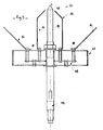
- this lightning rod will consist as a whole, for example, of a rod 11 terminated in the shape of a point 12 and connected to the ground by a connection 13 and at least one potential tap 14 carefully insulated from the tip by insulators 15, of any known type, chosen for their dielectric quality and their perfect resistance over time to atmospheric agents and to luminescent agents (ultraviolet rays).
- At least one spark electrode 16 is placed near the tip 12 and fixed, like the potential taps 14, in isolation from the tip 12.
- Electrodes 16 may, for this purpose, be arranged on an insulating support which will also have the advantage of fixing the distance between the tip 12 and the electrodes 16 in a perfectly constant manner.
- the potential-taking members 14 and the electrodes 16 are, by means of their isolation means, supported by a protective fairing 17 which is threaded on the tip 12 and which contains the card 18 with the printed circuit or wired and electronic components.
- the protective fairing 17 will preferably be metallic, stainless, perfectly weathertight with possibly a surface treatment such as nickel plating, to offer the components the maximum protection against induced currents due to the passage of lightning or capacitive effects. .
- the protective fairing 17 already alone constitutes excellent protection of the "Faraday cage” type: it is nevertheless conceivable to envisage a fairing made of plastic or composite materials having all the advantages of the metallic version.
- the card 18 and the electronic components will be embedded in a resin chosen for its dielectric qualities and for its excellent resistance to shock waves.
- the resin will, on the one hand, be insensitive to atmospheric parameters of the humidity type to ensure sealed operation of the assembly.
- the voltage U c sensed at the output of the diode 32 passes through a resistor 21 (for example of 750 ohms / 3 watts) before charging the capacitor 4 (for example 10 micro farads / 400 volts) up to a threshold (for example of 300 volts) determined by the zener diodes 22, 23.
- the detector 3 for exceeding the predetermined threshold for the gradient (dv / dt) of potential captured with respect to time consists, for example, of a high pass filter consisting of an RC circuit mounted as a shunt.
- the detector 3 transmits a signal to the device 10 for controlling the discharge of the capacitor 4.
- the control device 10 advantageously comprises an optocoupler 24 (for example of the MOC 3020 type) which delivers at the output through a resistor 25 (for example of 22 kilo ohms) a pulse controlling the trigger 27 of a triac 28 (by example of 8 amps / 400 volts).
- an optocoupler 24 for example of the MOC 3020 type
- a resistor 25 for example of 22 kilo ohms
- a pulse controlling the trigger 27 of a triac 28 by example of 8 amps / 400 volts.
- the triac then becomes on and releases all the energy accumulated in the capacitor 4 towards the supply circuit 5 for example through a pulse choke 29.
- a diode 26 (for example of the lN4004 type) placed upstream of the trigger 27 of the triac will then protect the latter from overvoltages due to the inductor.
- the circuit will also pass through a similar diode 30 avoiding the oscillation between the inductor and the capacitor.
- the device comprises a device 31 for protection against overvoltages (such as a surge protector UC350Q) which protects the components and the circuit against increases in voltages (in this example above 350 volts).
- a device 31 for protection against overvoltages such as a surge protector UC350Q
- UC350Q surge protector
Landscapes
- Elimination Of Static Electricity (AREA)
- Details Of Television Scanning (AREA)
- Insulators (AREA)
- Gas-Insulated Switchgears (AREA)
- Aiming, Guidance, Guns With A Light Source, Armor, Camouflage, And Targets (AREA)
- Details Of Aerials (AREA)
- Emergency Protection Circuit Devices (AREA)
Priority Applications (1)
| Application Number | Priority Date | Filing Date | Title |
|---|---|---|---|
| AT86402559T ATE55514T1 (de) | 1985-11-26 | 1986-11-19 | Blitzschutzverfahren, mittel zur ausfuehrung dieses verfahrens und blitzschutzanlage. |
Applications Claiming Priority (2)
| Application Number | Priority Date | Filing Date | Title |
|---|---|---|---|
| FR8517813A FR2590737B1 (fr) | 1985-11-26 | 1985-11-26 | Procede de protection contre la foudre, moyens pour la mise en oeuvre de ce procede et materiel de protection contre la foudre pourvu de ces moyens |
| FR8517813 | 1985-11-26 |
Publications (2)
| Publication Number | Publication Date |
|---|---|
| EP0228321A1 true EP0228321A1 (de) | 1987-07-08 |
| EP0228321B1 EP0228321B1 (de) | 1990-08-08 |
Family
ID=9325350
Family Applications (1)
| Application Number | Title | Priority Date | Filing Date |
|---|---|---|---|
| EP86402559A Expired - Lifetime EP0228321B1 (de) | 1985-11-26 | 1986-11-19 | Blitzschutzverfahren, Mittel zur Ausführung dieses Verfahrens und Blitzschutzanlage |
Country Status (9)
| Country | Link |
|---|---|
| US (1) | US4752854A (de) |
| EP (1) | EP0228321B1 (de) |
| JP (1) | JP2519433B2 (de) |
| AT (1) | ATE55514T1 (de) |
| CA (1) | CA1281372C (de) |
| DE (1) | DE3673367D1 (de) |
| ES (1) | ES2017636B3 (de) |
| FR (1) | FR2590737B1 (de) |
| GR (1) | GR3000967T3 (de) |
Cited By (3)
| Publication number | Priority date | Publication date | Assignee | Title |
|---|---|---|---|---|
| FR2624319A1 (fr) * | 1987-12-07 | 1989-06-09 | Lewiner Jacques | Dispositifs de protection contre la foudre a emission ionique |
| DE202008015873U1 (de) | 2008-12-01 | 2009-04-16 | Glinberg, Valeriy, Dipl.-Ing. | Waldblitzableiter |
| FR2943858A1 (fr) * | 2009-03-30 | 2010-10-01 | Indelec | Dispositif de protection contre l'effet d'un evenement physique tel que la foudre |
Families Citing this family (17)
| Publication number | Priority date | Publication date | Assignee | Title |
|---|---|---|---|---|
| US5216569B1 (en) * | 1991-05-24 | 1998-10-27 | Cable Innovations Inc | Method and apparatus for suppressing cable line transients |
| US5987335A (en) * | 1997-09-24 | 1999-11-16 | Lucent Technologies Inc. | Communication system comprising lightning protection |
| AU5804899A (en) | 1998-10-29 | 2000-05-22 | National Lightning Protection Corporation | A safer lightning rod and warning system |
| US6957117B2 (en) * | 2001-10-09 | 2005-10-18 | Public Service Electric And Gas Company | Portable protective air gap tool and method |
| KR100440616B1 (ko) * | 2003-09-06 | 2004-07-19 | 정용기 | 피뢰장치 |
| CN100391071C (zh) * | 2003-11-14 | 2008-05-28 | 万国雷迅科技集团有限公司 | 风水扇电离子避雷装置 |
| JP2005322518A (ja) * | 2004-05-10 | 2005-11-17 | Photonics:Kk | 導雷針装置 |
| CO6020013A1 (es) * | 2007-06-04 | 2009-03-31 | Barragan Humberto Arenas | Dispositivo para atenuar descargas atmosfericas |
| US7928604B2 (en) * | 2007-10-04 | 2011-04-19 | The Storm Shelter Corporation | Universal system for controlling automated transfer switches in response to external stimuli |
| FR2943487B1 (fr) | 2009-03-20 | 2016-12-09 | Indelec | Dispositif de protection contre l'effet d'un evenement physique tel que la foudre |
| FR2973598B1 (fr) | 2011-03-31 | 2014-01-03 | Indelec | Procede et installation de protection contre la foudre mettant en oeuvre un paratonnerre avec dispositif d'amorcage comportant une source de rayonnement electromagnetique |
| FR2973958B1 (fr) * | 2011-04-07 | 2015-09-04 | Indelec | Dispositif de protection contre la foudre avec electrode captrice presentant une extremite a geometrie virtuellement variable, et procede correspondant |
| FR3019693B1 (fr) | 2014-04-02 | 2016-05-13 | Indelec | Procede et dispositif de protection contre la foudre mettant en oeuvre un paratonnere avec moyens d'amorcage et moyens de neutralisation de la charge d'espace |
| JP6498945B2 (ja) * | 2015-01-15 | 2019-04-10 | 国立大学法人東北大学 | 蓄電装置及びその製造方法 |
| US10457413B2 (en) * | 2017-07-25 | 2019-10-29 | The Boeing Company | Methods and systems for aircraft lightning strike protection |
| CN113406726B (zh) * | 2021-06-01 | 2022-09-27 | 中国石油大学(北京) | 油气站场雷电事故预警方法、装置、设备及存储介质 |
| PL247952B1 (pl) | 2022-08-12 | 2025-09-22 | Eugeniusz Smycz | Urządzenie odgromowe wielkopowierzchniowych obiektów budowlanych, zwłaszcza z dachami wyposażonymi w panele fotowoltaiczne |
Citations (4)
| Publication number | Priority date | Publication date | Assignee | Title |
|---|---|---|---|---|
| FR907037A (fr) * | 1944-03-29 | 1946-02-27 | Paratonnerre électrodynamique | |
| EP0096655A1 (de) * | 1982-06-03 | 1983-12-21 | Energie Froide International SA | Blitzableiteranlage |
| GB2146851A (en) * | 1983-09-19 | 1985-04-24 | Angel Illa Arnau | Lightning conductor |
| EP0139575A2 (de) * | 1983-10-07 | 1985-05-02 | Helita S.A. | Selbstgespeiste Blitzschutzvorrichtung |
Family Cites Families (3)
| Publication number | Priority date | Publication date | Assignee | Title |
|---|---|---|---|---|
| FR1478526A (fr) * | 1966-03-11 | 1967-04-28 | Gen Prot Establishment | Paratonnerre à grande puissance ionisante |
| DE3260592D1 (en) * | 1981-03-06 | 1984-09-27 | Helita Societe Francaise | Ionizing lightning protector with corona effect |
| FR2543370B1 (fr) * | 1983-03-25 | 1986-03-07 | Commissariat Energie Atomique | Paratonnerre a dispositif piezo-electrique d'amorcage de l'effet corona. |
-
1985
- 1985-11-26 FR FR8517813A patent/FR2590737B1/fr not_active Expired - Lifetime
-
1986
- 1986-11-19 AT AT86402559T patent/ATE55514T1/de not_active IP Right Cessation
- 1986-11-19 EP EP86402559A patent/EP0228321B1/de not_active Expired - Lifetime
- 1986-11-19 ES ES86402559T patent/ES2017636B3/es not_active Expired - Lifetime
- 1986-11-19 DE DE8686402559T patent/DE3673367D1/de not_active Expired - Lifetime
- 1986-11-25 CA CA000523756A patent/CA1281372C/fr not_active Expired - Lifetime
- 1986-11-25 US US06/934,821 patent/US4752854A/en not_active Expired - Lifetime
- 1986-11-26 JP JP61281630A patent/JP2519433B2/ja not_active Expired - Lifetime
-
1990
- 1990-10-22 GR GR90400799T patent/GR3000967T3/el unknown
Patent Citations (4)
| Publication number | Priority date | Publication date | Assignee | Title |
|---|---|---|---|---|
| FR907037A (fr) * | 1944-03-29 | 1946-02-27 | Paratonnerre électrodynamique | |
| EP0096655A1 (de) * | 1982-06-03 | 1983-12-21 | Energie Froide International SA | Blitzableiteranlage |
| GB2146851A (en) * | 1983-09-19 | 1985-04-24 | Angel Illa Arnau | Lightning conductor |
| EP0139575A2 (de) * | 1983-10-07 | 1985-05-02 | Helita S.A. | Selbstgespeiste Blitzschutzvorrichtung |
Cited By (4)
| Publication number | Priority date | Publication date | Assignee | Title |
|---|---|---|---|---|
| FR2624319A1 (fr) * | 1987-12-07 | 1989-06-09 | Lewiner Jacques | Dispositifs de protection contre la foudre a emission ionique |
| EP0320358A1 (de) * | 1987-12-07 | 1989-06-14 | Jacques Lewiner | Blitzschutzeinrichtungen |
| DE202008015873U1 (de) | 2008-12-01 | 2009-04-16 | Glinberg, Valeriy, Dipl.-Ing. | Waldblitzableiter |
| FR2943858A1 (fr) * | 2009-03-30 | 2010-10-01 | Indelec | Dispositif de protection contre l'effet d'un evenement physique tel que la foudre |
Also Published As
| Publication number | Publication date |
|---|---|
| DE3673367D1 (de) | 1990-09-13 |
| JPS62216197A (ja) | 1987-09-22 |
| ES2017636B3 (es) | 1991-03-01 |
| FR2590737B1 (fr) | 1990-04-20 |
| US4752854A (en) | 1988-06-21 |
| CA1281372C (fr) | 1991-03-12 |
| FR2590737A1 (fr) | 1987-05-29 |
| GR3000967T3 (en) | 1991-12-10 |
| JP2519433B2 (ja) | 1996-07-31 |
| EP0228321B1 (de) | 1990-08-08 |
| ATE55514T1 (de) | 1990-08-15 |
Similar Documents
| Publication | Publication Date | Title |
|---|---|---|
| EP0228321B1 (de) | Blitzschutzverfahren, Mittel zur Ausführung dieses Verfahrens und Blitzschutzanlage | |
| CA1245710A (fr) | Paratonnerre a decharge couronne impulsionnelle intermittente | |
| EP0096655B1 (de) | Blitzableiteranlage | |
| EP0051006A2 (de) | Verfahren und Vorrichtungen zum Übertragen elektrischer Ladungen verschiedener Zeichen in ein Raumgebiet und Verwendung in Vorrichtungen zum Beseitigen statischer Elektrizität | |
| EP0596775B1 (de) | Blitzableiter mit Entzündungsvorrichtung mit gleitender elektrischer Entladung längs eines dielektrischen Teiles | |
| EP0056275B1 (de) | Einrichtung zum Schützen einer elektrischen Leitung vor sehr steile Flanken aufweisenden Störungen | |
| FR2553236A1 (fr) | Dispositif auto-alimente de protection contre la foudre | |
| EP1944848B1 (de) | Vorrichtung und Verfahren zur Messung der elektrischen Ladung eines Blitzes | |
| EP0123578B1 (de) | Blitzableiter mit piezoelektrischer Entzündungsvorrichtung des Corona-Effektes | |
| EP1887667B1 (de) | Zündvorrichtung mit zwei Elektroden für Funkenstrecke und entsprechende Verfahren | |
| EP0320358B1 (de) | Blitzschutzeinrichtungen | |
| EP0266264B1 (de) | Simulator eines Angriffs durch elektromagnetischen Puls | |
| FR2787964A1 (fr) | Electrificateur de cloture, a transformateur en faible masse | |
| EP1336233B1 (de) | Blitzableiter mit zündeinrichtung und verfahren zur steuerung des koronastroms eines solchen blitzableiters | |
| FR2536540A1 (fr) | Dispositif de detection de la presence de tension sur les installations electriques | |
| EP1665485B1 (de) | Blitzableiter mit pulsierender entzündungsvorrichtung mit gehaltenem laufzeit | |
| EP2509177B1 (de) | Blitzschutzvorrichtung mit Aufnehmerelektrode, die an einem Ende eine virtuell variable Geometrie aufweist, und entsprechendes Verfahren | |
| EP1628377B1 (de) | Schutzvorrichtung für elektrische Anlagen gegen Überspannungen einschliesslich einer Funkenstrecke mit Zündschaltung | |
| WO2001028058A1 (fr) | Perfectionnement a un paratonnerre a dispositif d'amorçage | |
| FR2849722A1 (fr) | Paratonnerre desionisant de charge electrostatique | |
| WO2015150663A1 (fr) | Procede et dispositif de protection contre la foudre mettant en oeuvre un paratonnere avec moyens d'amorçage et moyens de neutralisation de la charge d'espace | |
| WO2003098767A2 (fr) | Dispositif de protection d'un reseau de distribution d'energie electrique | |
| FR2702278A1 (fr) | Simulateur de champs à prédominance électrique, et son application aux essais d'équipements. | |
| FR3019391A1 (fr) | Dispositif de paratonnerre avec convertisseur d'effet couronne |
Legal Events
| Date | Code | Title | Description |
|---|---|---|---|
| PUAI | Public reference made under article 153(3) epc to a published international application that has entered the european phase |
Free format text: ORIGINAL CODE: 0009012 |
|
| AK | Designated contracting states |
Kind code of ref document: A1 Designated state(s): AT BE CH DE ES FR GB GR IT LI LU NL SE |
|
| 17P | Request for examination filed |
Effective date: 19870930 |
|
| 17Q | First examination report despatched |
Effective date: 19890721 |
|
| GRAA | (expected) grant |
Free format text: ORIGINAL CODE: 0009210 |
|
| AK | Designated contracting states |
Kind code of ref document: B1 Designated state(s): AT BE CH DE ES FR GB GR IT LI LU NL SE |
|
| PG25 | Lapsed in a contracting state [announced via postgrant information from national office to epo] |
Ref country code: AT Effective date: 19900808 Ref country code: SE Free format text: THE PATENT HAS BEEN ANNULLED BY A DECISION OF A NATIONAL AUTHORITY Effective date: 19900808 |
|
| REF | Corresponds to: |
Ref document number: 55514 Country of ref document: AT Date of ref document: 19900815 Kind code of ref document: T |
|
| REF | Corresponds to: |
Ref document number: 3673367 Country of ref document: DE Date of ref document: 19900913 |
|
| ITF | It: translation for a ep patent filed | ||
| GBT | Gb: translation of ep patent filed (gb section 77(6)(a)/1977) | ||
| REG | Reference to a national code |
Ref country code: GR Ref legal event code: FG4A Free format text: 3000967 |
|
| PLBE | No opposition filed within time limit |
Free format text: ORIGINAL CODE: 0009261 |
|
| STAA | Information on the status of an ep patent application or granted ep patent |
Free format text: STATUS: NO OPPOSITION FILED WITHIN TIME LIMIT |
|
| 26N | No opposition filed | ||
| ITTA | It: last paid annual fee | ||
| EPTA | Lu: last paid annual fee | ||
| REG | Reference to a national code |
Ref country code: GB Ref legal event code: IF02 |
|
| PGFP | Annual fee paid to national office [announced via postgrant information from national office to epo] |
Ref country code: FR Payment date: 20051005 Year of fee payment: 20 |
|
| PGFP | Annual fee paid to national office [announced via postgrant information from national office to epo] |
Ref country code: LU Payment date: 20051014 Year of fee payment: 20 |
|
| PGFP | Annual fee paid to national office [announced via postgrant information from national office to epo] |
Ref country code: NL Payment date: 20051018 Year of fee payment: 20 |
|
| PGFP | Annual fee paid to national office [announced via postgrant information from national office to epo] |
Ref country code: GR Payment date: 20051024 Year of fee payment: 20 |
|
| PGFP | Annual fee paid to national office [announced via postgrant information from national office to epo] |
Ref country code: GB Payment date: 20051028 Year of fee payment: 20 |
|
| PGFP | Annual fee paid to national office [announced via postgrant information from national office to epo] |
Ref country code: DE Payment date: 20051107 Year of fee payment: 20 |
|
| PGFP | Annual fee paid to national office [announced via postgrant information from national office to epo] |
Ref country code: CH Payment date: 20051111 Year of fee payment: 20 |
|
| PGFP | Annual fee paid to national office [announced via postgrant information from national office to epo] |
Ref country code: ES Payment date: 20051116 Year of fee payment: 20 |
|
| PGFP | Annual fee paid to national office [announced via postgrant information from national office to epo] |
Ref country code: IT Payment date: 20051118 Year of fee payment: 20 |
|
| PGFP | Annual fee paid to national office [announced via postgrant information from national office to epo] |
Ref country code: BE Payment date: 20051208 Year of fee payment: 20 |
|
| PG25 | Lapsed in a contracting state [announced via postgrant information from national office to epo] |
Ref country code: GB Free format text: LAPSE BECAUSE OF EXPIRATION OF PROTECTION Effective date: 20061118 |
|
| PG25 | Lapsed in a contracting state [announced via postgrant information from national office to epo] |
Ref country code: NL Free format text: LAPSE BECAUSE OF EXPIRATION OF PROTECTION Effective date: 20061119 |
|
| PG25 | Lapsed in a contracting state [announced via postgrant information from national office to epo] |
Ref country code: ES Free format text: LAPSE BECAUSE OF EXPIRATION OF PROTECTION Effective date: 20061120 |
|
| REG | Reference to a national code |
Ref country code: GB Ref legal event code: PE20 |
|
| REG | Reference to a national code |
Ref country code: CH Ref legal event code: PL |
|
| NLV7 | Nl: ceased due to reaching the maximum lifetime of a patent |
Effective date: 20061119 |
|
| REG | Reference to a national code |
Ref country code: ES Ref legal event code: FD2A Effective date: 20061120 |
|
| BE20 | Be: patent expired |
Owner name: *INDELEC SARL Effective date: 20061119 |