EP0228494A1 - Support sèche-linge - Google Patents
Support sèche-linge Download PDFInfo
- Publication number
- EP0228494A1 EP0228494A1 EP86100149A EP86100149A EP0228494A1 EP 0228494 A1 EP0228494 A1 EP 0228494A1 EP 86100149 A EP86100149 A EP 86100149A EP 86100149 A EP86100149 A EP 86100149A EP 0228494 A1 EP0228494 A1 EP 0228494A1
- Authority
- EP
- European Patent Office
- Prior art keywords
- arms
- laundry
- mast
- guide elements
- laundry rack
- Prior art date
- Legal status (The legal status is an assumption and is not a legal conclusion. Google has not performed a legal analysis and makes no representation as to the accuracy of the status listed.)
- Granted
Links
Images


Classifications
-
- D—TEXTILES; PAPER
- D06—TREATMENT OF TEXTILES OR THE LIKE; LAUNDERING; FLEXIBLE MATERIALS NOT OTHERWISE PROVIDED FOR
- D06F—LAUNDERING, DRYING, IRONING, PRESSING OR FOLDING TEXTILE ARTICLES
- D06F57/00—Supporting means, other than simple clothes-lines, for linen or garments to be dried or aired
- D06F57/02—Supporting means, other than simple clothes-lines, for linen or garments to be dried or aired mounted on pillars, e.g. rotatably
- D06F57/04—Supporting means, other than simple clothes-lines, for linen or garments to be dried or aired mounted on pillars, e.g. rotatably and having radial arms, e.g. collapsible
Definitions
- the present invention relates to a laundry rack with the features shown in the preamble of claim 1.
- a laundry rack of a similar type is e.g. known from CH-PS 390 863 and present in numerous embodiments on the market.
- Such a laundry rack can be brought from a position of use, in which a laundry rope is stretched between four projecting support arms and is thus ready to receive the laundry, into a folded rest position, in which the laundry rope sections extending loosely hang down between the support arms.
- the disadvantages here are that the loosely hanging laundry rope sections tend to get confused, that they are exposed to contamination if the entire laundry rack is not enclosed by a cover, and that a laundry rack folded to such an extent, when it is left at the place of use, is overall unaesthetic and looks messy due to the messy hanging rope sections.
- EP-PA 85113512.9 A problem that arises with a construction according to EP-PA 85113512.9 is that during the folding of the laundry rack for a clear and secure Introduce the loosely hanging rope sections into the cavities provided for receiving the same.
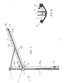
- the laundry rack 1 in the example has four arms 3 arranged at a uniform distance from one another about a vertically standing mast 2, which together serve as a carrier for a laundry rope 7 serve, the sections 7 ⁇ extend from support arm 3 to support arm 3 when they are in their spread apart position (use setting of the laundry rack), as shown in FIGS. 1 and 3.
- the connection of the arms 3 to the mast 2 takes place on the one hand via a support ring 4 which is arranged displaceably along the mast 2.
- the support ring 4 has radially projecting webs 5, to which the respective lower end of the arms 3 is pivotally attached.
- a strut 8 assigned to each arm 3 is provided, which is articulated to one end at a distance from the lower end of the arms 3.
- the other end, ie the end of the struts 8 facing away from the arm 3, is likewise pivotably mounted on a head part 10 of the mast 2.
- the support arms 3 are provided with laterally projecting wings which are either rigidly or pivotably attached to the arms 3, preferably in the region of their front edge.
- FIG. 4 An embodiment of such a construction is shown as a cross section in a horizontal plane through the closed laundry rack in FIG. 4.
- the mast 2 is formed by a generally cylindrical aluminum hollow profile, which, however, has four longitudinally extending depressions 9 arranged uniformly distributed along its circumference. These take up, in the folded state of the laundry rack, the support arms 3, the latter being formed by box profiles. Such an arrangement results in a pronounced stability in comparison small cross-sectional dimensions.
- the box profiles have a cavity 11 open towards the mast 2, in which the struts 8 dip.
- the part of the box sections facing away from the mast 2, which forms the arms 3, is provided with bores 12 for receiving the laundry rope 7.
- the outer, closed end of the box profiles is provided with two wing elements 6a, which are attached in the region of the outer edge of the arm 3 and protrude therefrom.
- These wing elements 6a can be part of the box profile, i.e. be integrally formed on this. They extend slightly inclined from the side surface 3a, at a slightly acute angle, towards the outside, the width of which is dimensioned such that its free edge 6 ⁇ comes to lie in the immediate vicinity of the free edge 6 ⁇ of the adjacent wing element 6a or even touches it .
- the laundry rack when the laundry rack is folded, four cavities 14 are created, which are delimited by two adjacent wing elements 6a, two adjacent outer surfaces 3a of the arms 3 and an area 2a of the outer surface of the mast 2.
- the hanging laundry rope sections 7a of the laundry rope 7 are accommodated in these four cavities 14.
- the length of the wing elements 6a is dimensioned such that the total length of the hanging cable sections is covered or "packed” with certainty; ie the wing elements 6a extend at least least from the bore 12 of the arms 3 provided for the outermost rope section 7a to the deflection point of the innermost rope section 7a. The exact length is to be determined in individual cases.
- guide elements are provided which are displaceably mounted along the arms and which, during the retraction of the arms 3, i. during the movement of the arms 3 from the spread-out operating position into the closed rest position resting against the mast 2, the loosely hanging laundry rope sections 7 'into the cavities 14.
- the guide element In the exemplary embodiment shown in FIG. 5, the guide element, generally designated 15, has the shape of an elongated guide body 16 which extends in the longitudinal direction of the arm 3 in question and can be freely displaced along the same.
- the laundry rack 1 has five arm-to-arm extensions Rope sections 7 ⁇ , which are each attached to the arm 3 at the ends.
- the length of the guide body 16 is chosen so that its longitudinal dimension corresponds approximately to the distance between the top and bottom rope section 7 ⁇ .
- the guide body 16 is provided with a first driver 17 which permanently overlaps the uppermost rope section 7 ⁇ and with further drivers 18 which temporarily overlap the rope sections below.
- first driver 17 which permanently overlaps the uppermost rope section 7 ⁇
- further drivers 18 which temporarily overlap the rope sections below.
- the shorter and shorter rope sections 7 ⁇ from top to bottom, which adjoin the uppermost rope section 7 ⁇ , are temporarily gripped by the catches 18, directed in the downward direction and towards the mast 2 and then released by the currently effective catch, in order to swivel in as they progress of the arm 3 and thus progressive displacement of the guide body 16 to be detected and guided by the subsequent driver 18.
- the guide body 16 can also be pushed down manually if this should be necessary, for example with a slightly jammed guide body or when using ropes that should be extremely stiff (eg due to very low temperature) , so that the dead weight of the guide body 16 is no longer sufficient for a perfect introduction of the cable sections 7 'into the cavities 14.
- each of the guide bodies 16 is equipped with two drivers 17 and with drivers 18 arranged in pairs, specifically in such a way that the two drivers 17 overlap the uppermost cable sections 7 'emanating from the associated arm 3 and the further drivers 18 arranged in pairs with the pairs below each of rope sections 7 ⁇ cooperate.
- the laundry rack 1 comprises a weight 19 arranged in the interior of its mast 2, which is connected to the lower end of the guide element 15 via a cable pull.
- the cable extends with a first section 20a from the weight 19 to a first deflection roller 21 at the head end of the mast 2, with a second section 20b from the first deflection roller 21 to a second deflection roller 22, and with a third section 20c from the second deflection roller 22 to the guide element 15.
- the cable comprises a first section 23a which extends from a lower anchoring point X, e.g. on the mast 2, up to a first deflecting roller 24, a second section 23b, which extends from the deflecting roller 24 to one end of the guide element 21, a third section 23c, which extends from the other end of the guide element 21 via one arranged at the end of the arm 3
- Deflection roller 25 leads to a third deflection roller 26, and finally a fourth section 23d from the third deflection roller 26 to an anchoring point Y, for example in the area of the upper end of the mast 2.
- the axes of rotation of the two deflection rollers 24 and 26 are not, as shown in the drawing, outside the arm 3, but rather coincide with the axis Z, i.e. with the pivot axis of the arm 3 on the support ring 4.
- the guide roller 25 is mounted at the end of the support arm 3.
- the guide element 21 is provided with a laterally protruding driver 22, which projects into the region of the cable sections 7 ′ extending from the arm 3.
- the cable sections 7 ⁇ when the guide element 21 is displaced in the direction of arrow P along the arm 3, are placed against the arm 3 and finally reach the cavities 14 mentioned above in an orderly manner.
Landscapes
- Engineering & Computer Science (AREA)
- Textile Engineering (AREA)
- Accessory Of Washing/Drying Machine, Commercial Washing/Drying Machine, Other Washing/Drying Machine (AREA)
- Transition And Organic Metals Composition Catalysts For Addition Polymerization (AREA)
- Detail Structures Of Washing Machines And Dryers (AREA)
Priority Applications (4)
| Application Number | Priority Date | Filing Date | Title |
|---|---|---|---|
| EP86100149A EP0228494B1 (fr) | 1986-01-08 | 1986-01-08 | Support sèche-linge |
| DE8686100149T DE3666056D1 (en) | 1986-01-08 | 1986-01-08 | Laundry dryer framework |
| AT86100149T ATE46929T1 (de) | 1986-01-08 | 1986-01-08 | Waeschegestell. |
| US06/940,629 US4735326A (en) | 1986-01-08 | 1986-12-11 | Clothes drying apparatus |
Applications Claiming Priority (1)
| Application Number | Priority Date | Filing Date | Title |
|---|---|---|---|
| EP86100149A EP0228494B1 (fr) | 1986-01-08 | 1986-01-08 | Support sèche-linge |
Publications (2)
| Publication Number | Publication Date |
|---|---|
| EP0228494A1 true EP0228494A1 (fr) | 1987-07-15 |
| EP0228494B1 EP0228494B1 (fr) | 1989-10-04 |
Family
ID=8194815
Family Applications (1)
| Application Number | Title | Priority Date | Filing Date |
|---|---|---|---|
| EP86100149A Expired EP0228494B1 (fr) | 1986-01-08 | 1986-01-08 | Support sèche-linge |
Country Status (3)
| Country | Link |
|---|---|
| EP (1) | EP0228494B1 (fr) |
| AT (1) | ATE46929T1 (fr) |
| DE (1) | DE3666056D1 (fr) |
Cited By (6)
| Publication number | Priority date | Publication date | Assignee | Title |
|---|---|---|---|---|
| EP0357803A1 (fr) * | 1988-07-29 | 1990-03-14 | LEIFHEIT Aktiengesellschaft | Dispositif pour protéger les cordes d'un séchoir à linge du type parapluie |
| EP0514561A1 (fr) * | 1991-05-18 | 1992-11-25 | LEIFHEIT Aktiengesellschaft | Support pour aération et séchage |
| EP0882833A1 (fr) * | 1997-06-05 | 1998-12-09 | LEIFHEIT Aktiengesellschaft | Support pour aération et séchage |
| EP1245715A3 (fr) * | 2001-03-30 | 2003-01-08 | Blome-Tillmann, Gerhard | Séchoir à linge |
| EP1760188A1 (fr) * | 2005-09-02 | 2007-03-07 | Stewi AG | Séchoir à linge pliable |
| EP2642015A1 (fr) * | 2012-03-19 | 2013-09-25 | Stewi AG | Châssis pour séchoir à linge |
Families Citing this family (3)
| Publication number | Priority date | Publication date | Assignee | Title |
|---|---|---|---|---|
| DE10345874B3 (de) * | 2003-09-30 | 2005-01-05 | Leifheit Ag | Wäschetrocknungsgestell |
| DE102004060508B3 (de) * | 2004-12-16 | 2006-03-30 | Leifheit Ag | Wäschetrocknungsgestell |
| DE102006014107A1 (de) | 2006-03-24 | 2007-09-27 | Leifheit Ag | Leineneinzugsbauteil |
Citations (6)
| Publication number | Priority date | Publication date | Assignee | Title |
|---|---|---|---|---|
| CH390863A (de) * | 1957-03-19 | 1965-04-30 | Goelz Brugger Alice Maria | Schirmartig zu betätigende Wäscheaufhängevorrichtung |
| EP0002599A1 (fr) * | 1977-12-12 | 1979-06-27 | William Gordon Hildreth | Améliorations relatives aux fils à sécher le linge |
| GB2055572A (en) * | 1979-06-14 | 1981-03-11 | Lin Ching Chang | Adjustable support assembly |
| EP0072930A1 (fr) * | 1981-08-21 | 1983-03-02 | LEIFHEIT Aktiengesellschaft | Dispositif pour séchage extérieur et aération de vêtements |
| DE3200013A1 (de) * | 1982-01-02 | 1983-08-11 | Leifheit International Günter Leifheit GmbH, 5408 Nassau | Lueftungs- und trocknungsgestell mit waescheleineneinzug |
| EP0113788A1 (fr) * | 1983-01-13 | 1984-07-25 | LEIFHEIT Aktiengesellschaft | Support pour aération et séchage |
-
1986
- 1986-01-08 DE DE8686100149T patent/DE3666056D1/de not_active Expired
- 1986-01-08 AT AT86100149T patent/ATE46929T1/de not_active IP Right Cessation
- 1986-01-08 EP EP86100149A patent/EP0228494B1/fr not_active Expired
Patent Citations (6)
| Publication number | Priority date | Publication date | Assignee | Title |
|---|---|---|---|---|
| CH390863A (de) * | 1957-03-19 | 1965-04-30 | Goelz Brugger Alice Maria | Schirmartig zu betätigende Wäscheaufhängevorrichtung |
| EP0002599A1 (fr) * | 1977-12-12 | 1979-06-27 | William Gordon Hildreth | Améliorations relatives aux fils à sécher le linge |
| GB2055572A (en) * | 1979-06-14 | 1981-03-11 | Lin Ching Chang | Adjustable support assembly |
| EP0072930A1 (fr) * | 1981-08-21 | 1983-03-02 | LEIFHEIT Aktiengesellschaft | Dispositif pour séchage extérieur et aération de vêtements |
| DE3200013A1 (de) * | 1982-01-02 | 1983-08-11 | Leifheit International Günter Leifheit GmbH, 5408 Nassau | Lueftungs- und trocknungsgestell mit waescheleineneinzug |
| EP0113788A1 (fr) * | 1983-01-13 | 1984-07-25 | LEIFHEIT Aktiengesellschaft | Support pour aération et séchage |
Cited By (6)
| Publication number | Priority date | Publication date | Assignee | Title |
|---|---|---|---|---|
| EP0357803A1 (fr) * | 1988-07-29 | 1990-03-14 | LEIFHEIT Aktiengesellschaft | Dispositif pour protéger les cordes d'un séchoir à linge du type parapluie |
| EP0514561A1 (fr) * | 1991-05-18 | 1992-11-25 | LEIFHEIT Aktiengesellschaft | Support pour aération et séchage |
| EP0882833A1 (fr) * | 1997-06-05 | 1998-12-09 | LEIFHEIT Aktiengesellschaft | Support pour aération et séchage |
| EP1245715A3 (fr) * | 2001-03-30 | 2003-01-08 | Blome-Tillmann, Gerhard | Séchoir à linge |
| EP1760188A1 (fr) * | 2005-09-02 | 2007-03-07 | Stewi AG | Séchoir à linge pliable |
| EP2642015A1 (fr) * | 2012-03-19 | 2013-09-25 | Stewi AG | Châssis pour séchoir à linge |
Also Published As
| Publication number | Publication date |
|---|---|
| ATE46929T1 (de) | 1989-10-15 |
| EP0228494B1 (fr) | 1989-10-04 |
| DE3666056D1 (en) | 1989-11-09 |
Similar Documents
| Publication | Publication Date | Title |
|---|---|---|
| EP0219571B1 (fr) | Support sèche-linge | |
| DE202014100745U1 (de) | Zweikammerbehälter mit Bodenklappen und Traversen | |
| EP0305623A1 (fr) | Séchoir à linge extensible | |
| EP0228494B1 (fr) | Support sèche-linge | |
| DE19906395A1 (de) | Theke zum Darbieten und/oder Verkaufen von Waren | |
| DE3200013A1 (de) | Lueftungs- und trocknungsgestell mit waescheleineneinzug | |
| EP0317737B1 (fr) | Dispositif pour un meuble d'angle, en particulier un meuble d'angle de cuisine | |
| DE2935876C2 (fr) | ||
| EP0229201B1 (fr) | Support sèche-linge | |
| DE4323993C3 (de) | Falt- oder raffbarer Vorhang | |
| DE69401704T2 (de) | Zweispurig tzag- und gleiteinrichtung für vorhänge | |
| DE3249358C2 (de) | Lüftungs- und Trocknungsgestell mit Wäscheleineneinzug | |
| EP3064385B1 (fr) | Structure de vehicule dotée d'une bache coulissante | |
| DE19621956B4 (de) | Markise mit zwangsläufig bewegtem Volant | |
| EP0276627A1 (fr) | Support pour linge | |
| DE19637341B4 (de) | Lüftungs- und Trocknungsgestell | |
| DE4229503C2 (de) | Lastkraftwagen-Kastenaufbau mit Seitenwand-Öffnungsmechanik | |
| EP0213280A2 (fr) | Séchoir à linge extensible | |
| DE19632973A1 (de) | Abschirm- oder Schutzvorrichtung für Wandöffnungen | |
| DE2602664A1 (de) | Wandwaeschetrockner | |
| DE2204217C3 (de) | Gartenschirm | |
| DE8101865U1 (de) | Futtergitter fuer viehstaelle | |
| DE3208564A1 (de) | Schwenkvorrichtung fuer schrankklappbetten | |
| DE2912514A1 (de) | Falttuer bzw. -wand | |
| DE2015418B1 (de) | Verkurzbarer Schirm mit aus mehr als einem Teil bestehenden Dachstangen |
Legal Events
| Date | Code | Title | Description |
|---|---|---|---|
| PUAI | Public reference made under article 153(3) epc to a published international application that has entered the european phase |
Free format text: ORIGINAL CODE: 0009012 |
|
| AK | Designated contracting states |
Kind code of ref document: A1 Designated state(s): AT BE CH DE FR GB IT LI LU NL SE |
|
| 17P | Request for examination filed |
Effective date: 19870903 |
|
| 17Q | First examination report despatched |
Effective date: 19880822 |
|
| ITTA | It: last paid annual fee | ||
| GRAA | (expected) grant |
Free format text: ORIGINAL CODE: 0009210 |
|
| AK | Designated contracting states |
Kind code of ref document: B1 Designated state(s): AT BE CH DE FR GB IT LI LU NL SE |
|
| REF | Corresponds to: |
Ref document number: 46929 Country of ref document: AT Date of ref document: 19891015 Kind code of ref document: T |
|
| REF | Corresponds to: |
Ref document number: 3666056 Country of ref document: DE Date of ref document: 19891109 |
|
| ET | Fr: translation filed | ||
| PGFP | Annual fee paid to national office [announced via postgrant information from national office to epo] |
Ref country code: AT Payment date: 19891211 Year of fee payment: 5 |
|
| PGFP | Annual fee paid to national office [announced via postgrant information from national office to epo] |
Ref country code: FR Payment date: 19891212 Year of fee payment: 5 |
|
| PGFP | Annual fee paid to national office [announced via postgrant information from national office to epo] |
Ref country code: SE Payment date: 19891215 Year of fee payment: 5 |
|
| PGFP | Annual fee paid to national office [announced via postgrant information from national office to epo] |
Ref country code: CH Payment date: 19891219 Year of fee payment: 5 |
|
| GBT | Gb: translation of ep patent filed (gb section 77(6)(a)/1977) | ||
| PGFP | Annual fee paid to national office [announced via postgrant information from national office to epo] |
Ref country code: BE Payment date: 19891220 Year of fee payment: 5 |
|
| PGFP | Annual fee paid to national office [announced via postgrant information from national office to epo] |
Ref country code: GB Payment date: 19891231 Year of fee payment: 5 |
|
| PGFP | Annual fee paid to national office [announced via postgrant information from national office to epo] |
Ref country code: DE Payment date: 19900102 Year of fee payment: 5 |
|
| ITF | It: translation for a ep patent filed | ||
| PGFP | Annual fee paid to national office [announced via postgrant information from national office to epo] |
Ref country code: LU Payment date: 19900109 Year of fee payment: 5 |
|
| PG25 | Lapsed in a contracting state [announced via postgrant information from national office to epo] |
Ref country code: LU Free format text: LAPSE BECAUSE OF NON-PAYMENT OF DUE FEES Effective date: 19900131 |
|
| PGFP | Annual fee paid to national office [announced via postgrant information from national office to epo] |
Ref country code: NL Payment date: 19900131 Year of fee payment: 5 |
|
| PLBE | No opposition filed within time limit |
Free format text: ORIGINAL CODE: 0009261 |
|
| STAA | Information on the status of an ep patent application or granted ep patent |
Free format text: STATUS: NO OPPOSITION FILED WITHIN TIME LIMIT |
|
| 26N | No opposition filed | ||
| PG25 | Lapsed in a contracting state [announced via postgrant information from national office to epo] |
Ref country code: GB Effective date: 19910108 Ref country code: AT Effective date: 19910108 |
|
| PG25 | Lapsed in a contracting state [announced via postgrant information from national office to epo] |
Ref country code: SE Effective date: 19910109 |
|
| PG25 | Lapsed in a contracting state [announced via postgrant information from national office to epo] |
Ref country code: LI Effective date: 19910131 Ref country code: CH Effective date: 19910131 Ref country code: BE Effective date: 19910131 |
|
| PG25 | Lapsed in a contracting state [announced via postgrant information from national office to epo] |
Ref country code: NL Effective date: 19910801 |
|
| GBPC | Gb: european patent ceased through non-payment of renewal fee | ||
| NLV4 | Nl: lapsed or anulled due to non-payment of the annual fee | ||
| PG25 | Lapsed in a contracting state [announced via postgrant information from national office to epo] |
Ref country code: FR Effective date: 19910930 |
|
| REG | Reference to a national code |
Ref country code: CH Ref legal event code: PL |
|
| PG25 | Lapsed in a contracting state [announced via postgrant information from national office to epo] |
Ref country code: DE Effective date: 19911001 |
|
| REG | Reference to a national code |
Ref country code: FR Ref legal event code: ST |
|
| EUG | Se: european patent has lapsed |
Ref document number: 86100149.3 Effective date: 19910910 |
|
| PG25 | Lapsed in a contracting state [announced via postgrant information from national office to epo] |
Ref country code: IT Free format text: LAPSE BECAUSE OF NON-PAYMENT OF DUE FEES Effective date: 20050108 |