EP0228542A1 - Dispositif d'entraînement à courroie, par exemple pour des dispositifs d'alimentation en fil pour des machines textiles - Google Patents
Dispositif d'entraînement à courroie, par exemple pour des dispositifs d'alimentation en fil pour des machines textiles Download PDFInfo
- Publication number
- EP0228542A1 EP0228542A1 EP86115533A EP86115533A EP0228542A1 EP 0228542 A1 EP0228542 A1 EP 0228542A1 EP 86115533 A EP86115533 A EP 86115533A EP 86115533 A EP86115533 A EP 86115533A EP 0228542 A1 EP0228542 A1 EP 0228542A1
- Authority
- EP
- European Patent Office
- Prior art keywords
- belt
- pulley
- output shaft
- drive device
- drive
- Prior art date
- Legal status (The legal status is an assumption and is not a legal conclusion. Google has not performed a legal analysis and makes no representation as to the accuracy of the status listed.)
- Granted
Links
Images
Classifications
-
- D—TEXTILES; PAPER
- D04—BRAIDING; LACE-MAKING; KNITTING; TRIMMINGS; NON-WOVEN FABRICS
- D04B—KNITTING
- D04B15/00—Details of, or auxiliary devices incorporated in, weft knitting machines, restricted to machines of this kind
- D04B15/94—Driving-gear not otherwise provided for
-
- B—PERFORMING OPERATIONS; TRANSPORTING
- B65—CONVEYING; PACKING; STORING; HANDLING THIN OR FILAMENTARY MATERIAL
- B65H—HANDLING THIN OR FILAMENTARY MATERIAL, e.g. SHEETS, WEBS, CABLES
- B65H51/00—Forwarding filamentary material
- B65H51/32—Supporting or driving arrangements for forwarding devices
-
- D—TEXTILES; PAPER
- D04—BRAIDING; LACE-MAKING; KNITTING; TRIMMINGS; NON-WOVEN FABRICS
- D04B—KNITTING
- D04B15/00—Details of, or auxiliary devices incorporated in, weft knitting machines, restricted to machines of this kind
- D04B15/38—Devices for supplying, feeding, or guiding threads to needles
- D04B15/48—Thread-feeding devices
-
- F—MECHANICAL ENGINEERING; LIGHTING; HEATING; WEAPONS; BLASTING
- F16—ENGINEERING ELEMENTS AND UNITS; GENERAL MEASURES FOR PRODUCING AND MAINTAINING EFFECTIVE FUNCTIONING OF MACHINES OR INSTALLATIONS; THERMAL INSULATION IN GENERAL
- F16G—BELTS, CABLES, OR ROPES, PREDOMINANTLY USED FOR DRIVING PURPOSES; CHAINS; FITTINGS PREDOMINANTLY USED THEREFOR
- F16G1/00—Driving-belts
- F16G1/28—Driving-belts with a contact surface of special shape, e.g. toothed
-
- F—MECHANICAL ENGINEERING; LIGHTING; HEATING; WEAPONS; BLASTING
- F16—ENGINEERING ELEMENTS AND UNITS; GENERAL MEASURES FOR PRODUCING AND MAINTAINING EFFECTIVE FUNCTIONING OF MACHINES OR INSTALLATIONS; THERMAL INSULATION IN GENERAL
- F16H—GEARING
- F16H7/00—Gearings for conveying rotary motion by endless flexible members
- F16H7/02—Gearings for conveying rotary motion by endless flexible members with belts; with V-belts
- F16H7/023—Gearings for conveying rotary motion by endless flexible members with belts; with V-belts with belts having a toothed contact surface or regularly spaced bosses or hollows for slipless or nearly slipless meshing with complementary profiled contact surface of a pulley
-
- B—PERFORMING OPERATIONS; TRANSPORTING
- B65—CONVEYING; PACKING; STORING; HANDLING THIN OR FILAMENTARY MATERIAL
- B65H—HANDLING THIN OR FILAMENTARY MATERIAL, e.g. SHEETS, WEBS, CABLES
- B65H2701/00—Handled material; Storage means
- B65H2701/30—Handled filamentary material
- B65H2701/31—Textiles threads or artificial strands of filaments
Definitions
- the invention relates to a belt drive device, for example for thread delivery devices for textile machines, with at least one endless driven belt and at least one output shaft, which can be coupled to a pulley over which the belt is guided and with which the belt is simultaneously a partially positive and partially frictional Has connection.
- a belt drive device of the type mentioned is known for example from DE-PS 23 65 251 and from DE-GM 74 19 793.
- There flat drive belts are used, which are provided in the middle with a row of holes, in which the pins of a central pin ring formed on the pulley engage and bring about a positive fit between the belt and the pulley, while the edge areas of the flat belt rest on the smooth edge areas of the pulley and there have frictional engagement with the pulley.
- the flat belt provided with a perforated disc has the advantage that it can be formed from one piece of belt by connecting the two ends of the belt together to form an endless belt, which is the case with toothed belts, such as are known from DE-OS 25 31 378, for example only positive drive connection between belt and toothed pulley over the full width, is not possible.
- the fully toothed drive belts must already be manufactured as endless belts, precisely tailored to the desired length.
- the invention has for its object to provide a belt drive device in which a slip-free drive with an endless belt is still guaranteed, which can be made from a straight piece of belt by connecting the belt ends, but in which a jumping off of the normally loaded belt is avoided.
- the stated object is achieved with a belt drive device of the type mentioned in the introduction in that the region or regions of the pulley which only give a frictional engagement with the belt or these regions of the region or regions of the pulley which form-fit with the belt is or are relatively rotatable.
- a frictional connection of the belt to the pulley can no longer disrupt the positive connection of the belt to the pulley.
- the frictional connection of the drive belt with a belt pulley can either be completely switched off in its effect by the part or parts of the belt pulley having a smooth contact surface for the belt can be freely rotatably supported, or its effect can only be reduced by the one or the a smooth contact surface for the belt-containing part or parts of the pulley are rotatably supported.
- These parts are appropriately stored on the output shaft, with which only the one or Width area or width areas of a drive-side pulley having recesses and / or projections is connected or can be coupled.
- the drive belt has, at least on its one longitudinal edge, a toothing formed by regularly arranged edge notches which engages in a toothed ring which can be coupled in a rotationally fixed manner to an output shaft and which forms the edge of a pulley, the adjacent, smooth contact surface for the toothless part of the drive belt coaxial part of the driven pulley forms a separate component rotatably mounted with respect to the ring gear.
- a belt drive device designed according to the invention can be used in many technical fields.
- An important area of application is thread delivery devices for textile machines, in which several drive belts rotating at different speeds are often provided at the same time, which are each to be coupled optionally with several output shafts via belt pulleys which can optionally be coupled to the output shaft.
- the toothed ring which cooperates with the edge toothing of the drive belt and the separate part of the belt pulley which forms the smooth belt contact surface can expediently be rotated freely with respect to one another and with respect to the output shaft, the toothed ring being provided with coupling recesses for the coupling projections of at least one axially adjustable, non-rotatable coupling plate .
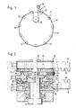
- Fig. 1 shows a belt drive device which is common to eleven thread delivery devices of a circular knitting machine. Of the thread delivery devices, only their drive part is of interest, not the rest of the structure.
- the eleven individual thread delivery devices are arranged on the circular knitting machine at regular intervals on a circle 10 indicated by dash-dotted lines and each have an output shaft 11 indicated by a circular interface in FIG. 1, with which at least one pulley 12 can be coupled.
- Both drive belts 14 and 15 are provided with an edge toothing by regularly arranged edge notches 16 and each formed by connecting the belt ends to form two endless drive belts.
- the endless drive belt 14 is guided over the pulleys 12 of all output shafts 11, runs over a stationary deflection roller 17 and an adjustable belt tensioning roller 18 and is set in motion by means of a drive wheel 19 at a desired drive speed.
- the drive wheel 19 can be adjusted in its belt support diameter, whereby a speed setting is possible.
- the drive wheel 19 can be fastened on a drive shaft of the circular knitting machine or on the shaft of a separate drive motor.
- both pulleys 12 and 13 are each freely rotatably supported on the output shaft 11 via a ball bearing 20 and 21.
- the pulleys 12 and 13 are of exactly the same design, only placed differently on the output shaft 11. They are divided into a ring gear 12.1, 13.1 and a drum part 12.2, 13.2.
- the ring gear 12.1, 13.1 forms one edge region of the pulley 12, 13.
- the ring gears 12.1 and 13.1 interact with the toothing 16 of the drive belts 14 and 15.
- the ring gear 13.1 with a central bearing ring 22 in the manner of a slide is arranged on a bearing sleeve part 23 of the drum part 13.2.
- the ball bearing 21 is cast into this bearing sleeve part 23.
- the ring gear 13.1 and the drum part 13.2 of the pulley 13 and, accordingly, the ring gear 12.1 and the drum part 12.2 of the pulley 12 can thus rotate against one another.
- a small edge flange 23.1 of the bearing sleeve part 23 prevents the ring gear 13.1 from axially displacing the drum part 13.2.
- the drum part 12.2, 13.2 forms a smooth contact surface for the toothless part of the drive belt 14 or 15.
- an axially adjustable clutch disc 24 Arranged between the pulley 12 and the pulley 13 is an axially adjustable clutch disc 24, which is shown in section in the left half of FIG. 2 and in a different axial position than in the right half.
- the clutch disc 24 is provided on both ends with clutch projections 25 and 26 which are arranged on the same diameter circles and in the same distribution as clutch recesses 27 which are formed in the ring gears 12.1 and 13.1.
- the clutch disc 24 is arranged in a rotationally fixed concentric manner on a clutch carrier 28 which is pushed onto the output shaft 11 and which, in a manner not shown in FIG. 2, is designed on its circumference as a regular polygon, for example a regular hexagon, and on one of these outer sides with three in the left part of the Fig.
- the clutch carrier 28 is by means of a screw 31 which is in a concentric Ge Wind bore 32 is anchored in the free end of the output shaft 11, clamped between the two ball bearings 20 and 21.
- the clutch disc 24 with its locking lug 30 is located in the lowermost of the three locking notches 29 of the clutch carrier 28. In this position, the clutch projections 25 of the clutch disc 24 engage in the clutch recesses 27 of the ring gear 13.1 of the pulley 13 and thus effect a rotationally fixed coupling of the ring gear 13.1 to the output shaft 11.
- the drum part 13.2 of the pulley 13 remains freely rotatable on the output shaft 11.
- the clutch disc 24, not shown there in section, is shown in its uppermost position, in which its coupling projections 26 engage in the corresponding coupling recesses of the ring gear 12.2 of the belt pulley 12 and couple the ring gear 12.1 to the output shaft 11 in a rotationally fixed manner. There, too, the drum part 12.2 of the pulley 12 always remains freely rotatable.
- both gear rings 12.1 and 13.1 remain disengaged.
- Both pulleys 12 and 13, including their sprockets 12.1, 13.1, rotate freely, and the output shaft 11 remains at rest.
Landscapes
- Engineering & Computer Science (AREA)
- General Engineering & Computer Science (AREA)
- Textile Engineering (AREA)
- Mechanical Engineering (AREA)
- Pulleys (AREA)
- Devices For Conveying Motion By Means Of Endless Flexible Members (AREA)
- Forwarding And Storing Of Filamentary Material (AREA)
- Knitting Machines (AREA)
Applications Claiming Priority (2)
| Application Number | Priority Date | Filing Date | Title |
|---|---|---|---|
| DE3543183 | 1985-12-06 | ||
| DE3543183A DE3543183C1 (de) | 1985-12-06 | 1985-12-06 | Riemenantriebsvorrichtung,beispielsweise fuer Fadenliefervorrichtungen fuer Textilmaschinen |
Publications (2)
| Publication Number | Publication Date |
|---|---|
| EP0228542A1 true EP0228542A1 (fr) | 1987-07-15 |
| EP0228542B1 EP0228542B1 (fr) | 1989-09-27 |
Family
ID=6287823
Family Applications (1)
| Application Number | Title | Priority Date | Filing Date |
|---|---|---|---|
| EP86115533A Expired EP0228542B1 (fr) | 1985-12-06 | 1986-11-08 | Dispositif d'entraînement à courroie, par exemple pour des dispositifs d'alimentation en fil pour des machines textiles |
Country Status (6)
| Country | Link |
|---|---|
| US (1) | US4738652A (fr) |
| EP (1) | EP0228542B1 (fr) |
| JP (1) | JPS62137461A (fr) |
| DD (1) | DD252591A5 (fr) |
| DE (1) | DE3543183C1 (fr) |
| ES (1) | ES2011005B3 (fr) |
Cited By (2)
| Publication number | Priority date | Publication date | Assignee | Title |
|---|---|---|---|---|
| EP0333482A1 (fr) * | 1988-03-18 | 1989-09-20 | Precision Fukuhara Works, Ltd | Fournisseur positif pour métier à tricoter circulaire |
| EP0350976A1 (fr) * | 1988-07-11 | 1990-01-17 | Jen-Fu Chen | Dispositif d'alimentation en fil synchrone |
Families Citing this family (1)
| Publication number | Priority date | Publication date | Assignee | Title |
|---|---|---|---|---|
| JP7497220B2 (ja) * | 2020-06-09 | 2024-06-10 | ナブテスコ株式会社 | 減速機、及び、駆動装置 |
Citations (4)
| Publication number | Priority date | Publication date | Assignee | Title |
|---|---|---|---|---|
| FR1096002A (fr) * | 1954-03-17 | 1955-06-08 | Organe de transmission de mouvement | |
| FR2227365A1 (fr) * | 1973-04-30 | 1974-11-22 | Iro Ab | |
| FR2408674A1 (fr) * | 1977-08-26 | 1979-06-08 | Asa Sa | Dispositif perfectionne de commande de l'entrainement des fournisseurs de fil pour metiers a tricoter |
| DE3307007A1 (de) * | 1983-02-28 | 1984-08-30 | Horst 7407 Rottenburg Paepke | Fadenliefervorrichtung |
Family Cites Families (6)
| Publication number | Priority date | Publication date | Assignee | Title |
|---|---|---|---|---|
| DE7419793U (de) * | 1975-10-09 | Skf Kugellagerfabriken Gmbh | Fadenliefervorrichtung für eine Wirkoder Strickmaschine | |
| US1144414A (en) * | 1915-04-05 | 1915-06-29 | Atlas Educational Film Co | Film and sprocket-drum. |
| US3338107A (en) * | 1965-02-15 | 1967-08-29 | Kiekhaefer Corp | Positive drive system |
| DE2365251C2 (de) * | 1973-04-30 | 1983-02-17 | Aktiebolaget Iro, Ulricehamn | Fadenliefervorrichtung für Textilmaschinen |
| FR2278817A1 (fr) * | 1974-07-17 | 1976-02-13 | Inst Textile De France | Dispositif d'alimentation en fil pour metier de bonneterie |
| US4015484A (en) * | 1976-02-20 | 1977-04-05 | Miller Taylor | Guide pulley for wide belts |
-
1985
- 1985-12-06 DE DE3543183A patent/DE3543183C1/de not_active Expired
-
1986
- 1986-11-08 ES ES86115533T patent/ES2011005B3/es not_active Expired
- 1986-11-08 EP EP86115533A patent/EP0228542B1/fr not_active Expired
- 1986-12-04 JP JP61287889A patent/JPS62137461A/ja active Granted
- 1986-12-05 US US06/938,789 patent/US4738652A/en not_active Expired - Lifetime
- 1986-12-05 DD DD86297140A patent/DD252591A5/de not_active IP Right Cessation
Patent Citations (4)
| Publication number | Priority date | Publication date | Assignee | Title |
|---|---|---|---|---|
| FR1096002A (fr) * | 1954-03-17 | 1955-06-08 | Organe de transmission de mouvement | |
| FR2227365A1 (fr) * | 1973-04-30 | 1974-11-22 | Iro Ab | |
| FR2408674A1 (fr) * | 1977-08-26 | 1979-06-08 | Asa Sa | Dispositif perfectionne de commande de l'entrainement des fournisseurs de fil pour metiers a tricoter |
| DE3307007A1 (de) * | 1983-02-28 | 1984-08-30 | Horst 7407 Rottenburg Paepke | Fadenliefervorrichtung |
Cited By (2)
| Publication number | Priority date | Publication date | Assignee | Title |
|---|---|---|---|---|
| EP0333482A1 (fr) * | 1988-03-18 | 1989-09-20 | Precision Fukuhara Works, Ltd | Fournisseur positif pour métier à tricoter circulaire |
| EP0350976A1 (fr) * | 1988-07-11 | 1990-01-17 | Jen-Fu Chen | Dispositif d'alimentation en fil synchrone |
Also Published As
| Publication number | Publication date |
|---|---|
| DE3543183C1 (de) | 1987-05-14 |
| EP0228542B1 (fr) | 1989-09-27 |
| US4738652A (en) | 1988-04-19 |
| DD252591A5 (de) | 1987-12-23 |
| ES2011005B3 (es) | 1989-12-16 |
| JPH028176B2 (fr) | 1990-02-22 |
| JPS62137461A (ja) | 1987-06-20 |
Similar Documents
| Publication | Publication Date | Title |
|---|---|---|
| DE3506552A1 (de) | Garnzufuhrvorrichtung fuer die zwangslaeufige garnzufuhr zu einer strickmaschine | |
| WO1986007101A1 (fr) | Transmission a courroie tangentielle | |
| EP0063690A1 (fr) | Dispositif pour le bobinage d'un fil | |
| EP0228542B1 (fr) | Dispositif d'entraînement à courroie, par exemple pour des dispositifs d'alimentation en fil pour des machines textiles | |
| DE3340825C2 (fr) | ||
| DE2528205C2 (de) | Faserauflösevorrichtung für eine mit Unterdruck arbeitende Spinnvorrichtung | |
| EP0412376B1 (fr) | Installation pour rectifier les fils de trame d'un tissu | |
| DE3422814A1 (de) | Antriebsvorrichtung fuer eine paraffiniereinrichtung | |
| EP0026350B1 (fr) | Dispositif délivreur de fil, en particulier pour un fil fraîchement teint | |
| DE2506058A1 (de) | Faserbandaufloesevorrichtung fuer eine offenend-spinneinrichtung | |
| EP0714770B1 (fr) | Dispositif pour transporter du papier | |
| DE2213851B1 (de) | Vorrichtung zum falschzwirnen von insbesondere synthetischen faeden od. dgl. mittels friktionsgetrieben | |
| DE1286680B (de) | Garnzubringer | |
| DE2451025B2 (de) | Förderer mit einer um Umlenkräder geführten endlosen Förderkette | |
| DE3307881A1 (de) | Antrieb fuer die rauhwalzen einer tambour-rauhmaschine | |
| EP0000729A1 (fr) | Mandrin pour l'enroulement simultané de plusieurs bandes | |
| DE2356071B2 (de) | Vorrichtung zur Außenbearbeitung von Grafit-, Färb-, Kosmetikstiften o.dgl | |
| DE644233C (de) | Antrieb fuer Rauhwalzen an Trommelrauhmaschinen | |
| DE2203409C3 (de) | Falschdrallvorrichtung | |
| DE202004002756U1 (de) | Umlenkförderer | |
| DE2902023C2 (de) | Fadenliefervorrichtung für Strickmaschinen | |
| DE688907C (de) | Stauchfalzmaschine zum Parallelfalzen | |
| EP0412375A1 (fr) | Installation pour rectifier les fils de trame d'un tissu | |
| DE1207544B (de) | Vorrichtung zum Erzeugen eines Falschdralles | |
| DE1585209B1 (de) | Warenaufwickelvorrichtung fuer Kettenwirkmaschinen |
Legal Events
| Date | Code | Title | Description |
|---|---|---|---|
| PUAI | Public reference made under article 153(3) epc to a published international application that has entered the european phase |
Free format text: ORIGINAL CODE: 0009012 |
|
| AK | Designated contracting states |
Kind code of ref document: A1 Designated state(s): ES GB IT SE |
|
| 17P | Request for examination filed |
Effective date: 19870813 |
|
| 17Q | First examination report despatched |
Effective date: 19890302 |
|
| GRAA | (expected) grant |
Free format text: ORIGINAL CODE: 0009210 |
|
| AK | Designated contracting states |
Kind code of ref document: B1 Designated state(s): ES GB IT SE |
|
| ITF | It: translation for a ep patent filed | ||
| GBT | Gb: translation of ep patent filed (gb section 77(6)(a)/1977) | ||
| PLBE | No opposition filed within time limit |
Free format text: ORIGINAL CODE: 0009261 |
|
| STAA | Information on the status of an ep patent application or granted ep patent |
Free format text: STATUS: NO OPPOSITION FILED WITHIN TIME LIMIT |
|
| 26N | No opposition filed | ||
| ITTA | It: last paid annual fee | ||
| EAL | Se: european patent in force in sweden |
Ref document number: 86115533.1 |
|
| PGFP | Annual fee paid to national office [announced via postgrant information from national office to epo] |
Ref country code: SE Payment date: 20010918 Year of fee payment: 16 |
|
| PGFP | Annual fee paid to national office [announced via postgrant information from national office to epo] |
Ref country code: GB Payment date: 20011029 Year of fee payment: 16 |
|
| PGFP | Annual fee paid to national office [announced via postgrant information from national office to epo] |
Ref country code: ES Payment date: 20011106 Year of fee payment: 16 |
|
| REG | Reference to a national code |
Ref country code: GB Ref legal event code: IF02 |
|
| PG25 | Lapsed in a contracting state [announced via postgrant information from national office to epo] |
Ref country code: GB Free format text: LAPSE BECAUSE OF NON-PAYMENT OF DUE FEES Effective date: 20021108 |
|
| PG25 | Lapsed in a contracting state [announced via postgrant information from national office to epo] |
Ref country code: SE Free format text: LAPSE BECAUSE OF NON-PAYMENT OF DUE FEES Effective date: 20021109 Ref country code: ES Free format text: LAPSE BECAUSE OF NON-PAYMENT OF DUE FEES Effective date: 20021109 |
|
| GBPC | Gb: european patent ceased through non-payment of renewal fee | ||
| EUG | Se: european patent has lapsed | ||
| REG | Reference to a national code |
Ref country code: ES Ref legal event code: FD2A Effective date: 20031213 |
|
| PG25 | Lapsed in a contracting state [announced via postgrant information from national office to epo] |
Ref country code: IT Free format text: LAPSE BECAUSE OF NON-PAYMENT OF DUE FEES;WARNING: LAPSES OF ITALIAN PATENTS WITH EFFECTIVE DATE BEFORE 2007 MAY HAVE OCCURRED AT ANY TIME BEFORE 2007. THE CORRECT EFFECTIVE DATE MAY BE DIFFERENT FROM THE ONE RECORDED. Effective date: 20051108 |