EP0228558A1 - Circuit pour la surveillance sélective de flammes d'installations à brûleurs multiples - Google Patents
Circuit pour la surveillance sélective de flammes d'installations à brûleurs multiples Download PDFInfo
- Publication number
- EP0228558A1 EP0228558A1 EP86116128A EP86116128A EP0228558A1 EP 0228558 A1 EP0228558 A1 EP 0228558A1 EP 86116128 A EP86116128 A EP 86116128A EP 86116128 A EP86116128 A EP 86116128A EP 0228558 A1 EP0228558 A1 EP 0228558A1
- Authority
- EP
- European Patent Office
- Prior art keywords
- flop
- mono
- retriggerable
- circuit arrangement
- output
- Prior art date
- Legal status (The legal status is an assumption and is not a legal conclusion. Google has not performed a legal analysis and makes no representation as to the accuracy of the status listed.)
- Granted
Links
- 238000012544 monitoring process Methods 0.000 title claims abstract description 14
- 238000009434 installation Methods 0.000 title claims abstract 3
- 238000011156 evaluation Methods 0.000 claims abstract description 15
- 230000005693 optoelectronics Effects 0.000 claims abstract description 12
- 239000003990 capacitor Substances 0.000 claims abstract description 4
- 230000005540 biological transmission Effects 0.000 description 13
- 230000005855 radiation Effects 0.000 description 10
- 238000002485 combustion reaction Methods 0.000 description 5
- 238000010586 diagram Methods 0.000 description 5
- 239000000446 fuel Substances 0.000 description 5
- 238000003384 imaging method Methods 0.000 description 4
- 238000012545 processing Methods 0.000 description 3
- 239000007788 liquid Substances 0.000 description 2
- 238000004886 process control Methods 0.000 description 2
- 239000007787 solid Substances 0.000 description 2
- 230000002123 temporal effect Effects 0.000 description 2
- 238000006243 chemical reaction Methods 0.000 description 1
- 230000001419 dependent effect Effects 0.000 description 1
- 238000005516 engineering process Methods 0.000 description 1
- 230000010354 integration Effects 0.000 description 1
- 238000000034 method Methods 0.000 description 1
- 230000000737 periodic effect Effects 0.000 description 1
- 238000001454 recorded image Methods 0.000 description 1
- 238000004088 simulation Methods 0.000 description 1
- 238000012549 training Methods 0.000 description 1
- 230000001960 triggered effect Effects 0.000 description 1
Images

Classifications
-
- G—PHYSICS
- G01—MEASURING; TESTING
- G01R—MEASURING ELECTRIC VARIABLES; MEASURING MAGNETIC VARIABLES
- G01R23/00—Arrangements for measuring frequencies; Arrangements for analysing frequency spectra
- G01R23/02—Arrangements for measuring frequency, e.g. pulse repetition rate; Arrangements for measuring period of current or voltage
- G01R23/15—Indicating that frequency of pulses is either above or below a predetermined value or within or outside a predetermined range of values, by making use of non-linear or digital elements (indicating that pulse width is above or below a certain limit)
-
- F—MECHANICAL ENGINEERING; LIGHTING; HEATING; WEAPONS; BLASTING
- F23—COMBUSTION APPARATUS; COMBUSTION PROCESSES
- F23N—REGULATING OR CONTROLLING COMBUSTION
- F23N5/00—Systems for controlling combustion
- F23N5/02—Systems for controlling combustion using devices responsive to thermal changes or to thermal expansion of a medium
- F23N5/08—Systems for controlling combustion using devices responsive to thermal changes or to thermal expansion of a medium using light-sensitive elements
- F23N5/082—Systems for controlling combustion using devices responsive to thermal changes or to thermal expansion of a medium using light-sensitive elements using electronic means
-
- H—ELECTRICITY
- H03—ELECTRONIC CIRCUITRY
- H03K—PULSE TECHNIQUE
- H03K5/00—Manipulating of pulses not covered by one of the other main groups of this subclass
- H03K5/125—Discriminating pulses
- H03K5/1252—Suppression or limitation of noise or interference
-
- F—MECHANICAL ENGINEERING; LIGHTING; HEATING; WEAPONS; BLASTING
- F23—COMBUSTION APPARATUS; COMBUSTION PROCESSES
- F23N—REGULATING OR CONTROLLING COMBUSTION
- F23N2237/00—Controlling
- F23N2237/02—Controlling two or more burners
Definitions
- the invention relates to a circuit arrangement for selective flame monitoring in multi-burner systems for solid, liquid or gaseous fuels, consisting of an optoelectronic sensor unit in which the optoelectronic sensor element is connected to a pulse shaper via a capacitor, and an electronic evaluation and switching unit.
- Multi-burner systems are operated via a number of individual burners that radiate into a common combustion chamber.
- the special task of selective flame monitoring in these systems is that the individual burner flames separated, "a flame” or “flame” of the remaining burners must be grasped that is independent of the state to dangerous Flameout to avoid fuel concentrations, the fuel s Stop the fuel supply for the burner in question immediately.
- the sensor elements used to monitor the flame also pick up external signals that arise after the flame has been extinguished due to streaking on the afterglowing parts in the combustion chamber (background radiation) or from temporarily irradiated flame tips from neighboring burner flames.
- the difficulty lies in making a clear and unambiguous distinction between the external signals in the low-frequency range with relatively large amplitude values in the "flame off” state and the overlying frequency range of the useful signals with relatively small amplitude values in the "flame present” state and with a short response time.
- the invention seeks to remedy this.
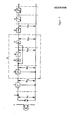
- the invention solves the problem of creating a circuit arrangement for selective flame monitoring in multi-burner systems for solid, liquid or gaseous fuels, which realizes maximum selectivity with short response times with simple circuitry means and low component expenditure, the occurrence of unjustified Reduced lockouts and thus guarantees high availability and security against pretending flame, in that the output of the pulse shaper is connected to a retriggerable mono-flop and its output is connected to an inverter and also to the first input of an AND gate and that in series with the Inverter another mono-flop is connected, the output of which is connected to the second input of the AND gate and that the output of the AND gate is connected to a further retriggerable mono-flop which controls the switching unit.
- the hold time of the first is retriggerable Mono-flop t M10 to the upper frequency limit of the desired pass band f DO according to the relationship and the hold time of further mono-flops t M20 connected in series with the inverter to the lower frequency limit of the desired pass band f DU according to the relationship set.
- the holding time of the retriggerable mono-flop that controls the switching unit must be set greater than the sum of the holding times of the first two mono-flops and less than the permissible switch-off delay time.
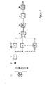
- n-evaluation units first retriggerable mono-flop, inverter, further mono-flop and AND-gate
- the inputs of the Evaluation units are located and their n outputs are connected via an additional OR gate to the retriggerable mono-flop, which controls the switching unit.
- a further improvement is achieved in that an integrating element is arranged between the second retriggerable mono-flop and the switching unit.
- the hold time of the second retriggerable mono flop must be less than the sum of the hold times of the first two mono flops and greater than the hold time of the first retriggerable mono flop be posed.
- the switching unit is designed as a threshold switch.
- the function of the circuit arrangement will then be described.
- the analog image signals converted from the pulsating portion of the flame radiation by the optoelectronic sensor element or the external signals still radiated onto the optoelectronic sensor element are shaped in the pulse shaper into digital signals whose pulse repetition frequency corresponds to the frequency of the recorded image signals.
- the evaluation unit following the pulse shaper consisting of the retriggerable mono-flop, the inverter, the further mono-flop and the AND gate, represents a "pulse frequency window", which causes that at the output of the AND gate only then An output pulse occurs when the time interval between the LH edges of two immediately following input pulses is greater than the hold time of the retriggerable mono flop and less than the sum of the hold times of the two mono flops.
- the LH edge of the first pulse starts the retriggerable mono-flop, which starts the second mono-flop via the inverter after the hold time has elapsed, and which keeps the AND gate open during its hold time, so that only one in this time falling LH edge of the next pulse appears at the output of the AND gate.
- the pulse train reaching the "pulse frequency window" from the pulse shaper only generates a pulse train of the same frequency at the output of the AND gate if the imaging signals are within the set frequency limits.
- the parallel connection of several evaluation units enables the transmission of a large frequency range, from which the characteristic interference frequency ranges are completely masked out.
- the output pulse train is converted with the help of the second retriggerable mono-flop into the flame presence signal, which reaches the input of the switching unit, which takes over the process control.
- triggering of the switching unit when the flame is extinguished is avoided by short pulse scattering of isolated external signals from adjacent burner flames.
- Frequencies of the recorded flame signal from the associated burner flame the period of which is shorter than the holding time tM30, cause the second retriggerable mono-flop to be retriggered continuously.
- Flame signals with lower frequencies (but within the transmission range) appear unchanged at the output of the second retriggerable mono-flop and are converted into a pulsating DC voltage by means of the following integrating element, which constantly remains above the switching threshold of the switching unit.
- the invention thus provides a circuit arrangement for selective flame monitoring in multi-burner systems, which works according to the alternating radiation principle and which transmits a useful signal evaluation area required for the selection of flames with a predetermined frequency limitation and absolutely blocks the external signals occurring outside these limits, regardless of their amplitude size.
- Simple means of digital technology are used, which enable a single pulse evaluation and avoid counter connections and the use of microprocessors.
- the required pass bands are transmitted individually or in combination with any upper and lower frequency limit (e.g. 60 Hz ... 90 Hz, 130 Hz ... 150 Hz, 200 Hz ... 300 Hz etc.).
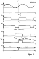
- the imaging signal voltage ie the input signal voltage U E and its frequency f E , run periodically in a short period of time.
- the retriggerable mono-flop 4 is set with the LH flank of the square-wave signal voltage U TE , ie the output voltage U M1 is set to H level.
- f DU 60 Hz
- f DO 90 Hz
- the output voltage U M1 tilts back to L level at time t M10 and is set low to H level at time t E (following LH edge) etc.
- the output voltage U M1 therefore has a temporal level curve of:
- t M1H is the period of the H level
- t M1L is the period of the L level of U M1 .
- the output voltage U M1 is fed via the inverter 5 to the input of the mono-flop 6 and also to the first input of the AND gate 7. With the HL flank of the output voltage U M1 which occurs at the time t M10 , the mono-flop 6 is set so that its output voltage U M2 assumes H potential. The output voltage U M2 then tilts back to the L level after the holding time t M20 has elapsed and is set to the H level again after a further period of time from t E - t M20 (following HL edge from U M1 ), etc.
- the output voltage U So M2 has a temporal level curve of: and etc. , where t M2H is the duration of the H level and t M2L is the duration of the L level of U M2 .
- the output voltages U M1 and U M2 are from the time t E to t M10 + t M20 at the same time at H level, which is then also present at the output of the AND gate 7.
- the output voltage U A1 of the AND gate 7 falls back to the L level at the time t M10 + t M20 and is set to the H level again after a further time lapse from t E - (t M10 + t M20 ).
- the output voltage U A1 therefore has a time-related level curve of and ETC, where t A1H is the duration of the H level and t A1L is the duration of the L level of the output voltage U A1 .
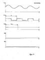
- the following retriggerable mono-flop 9 is set with the LH edge of the output voltage U A1 , ie its output voltage U A2 is set to H level.
- the holding time t M30 of the retriggerable mono-flop 9 is dependent on the relationship, depending on the burner arrangement, the orientation of the sensor viewing opening and other system-specific conditions, on the lower frequency limit of the pass band f DU set.
- the hold time t M10 of the retriggerable mono-flop 4 is greater than the period t E of the input signal voltage, so that the mono-flop is retriggered continuously.
- Flops 4 take place before the end of its holding time and the mono-flop 6 cannot be started via the inverter 5. Since different signal levels are thus present at the AND gate 7, the mono-flop 9 is no longer retriggered, so that after the holding time tM30 and the output voltage of the integrating element 11 drop below the threshold voltage of the threshold switch 10, the control command "flame off" is issued.
- the period t E of the input signal voltage is greater than the sum of the hold times of the mono-flops 4 and 6, so that the retriggerable periodic start Mono-flops 4 only take place when the holding time t M20 of the mono-flop 6 has already expired.
- the two inputs of the AND gate 7 are consequently never at H potential at the same time, as a result of which the switching unit 10 no longer receives a flame presence signal. If the burner flame fails, the optoelectronic sensor element 1, in addition to the radiation already mentioned, lies outside the transmission range of the arrangement, depending on the specific conditions of the system and the like.
- the frequency within the Transmission range can be. These disturbances reach the input of the integrating element 11 via the signal path and are converted by the latter into a pulsating direct voltage, which constantly remains below the threshold value of the threshold value switch 10.
- the transmission of several characteristic frequency ranges by connecting several evaluation units A 1 ... n in parallel according to FIG. 2 has the advantage that the circuit arrangement recognizes an existing burner flame as such with high certainty even if this fluctuates in the flame quality, for example as a result of control processes. Furthermore, the consistent digital signal processing achieves a high selectivity with a short response time, since known burner and combustion chamber-typical interference frequency ranges, which could lead to a flame pretense, can be eliminated from the frequency band to be transmitted without delay and absolutely by individual pulse evaluation.
- the circuit arrangement according to the invention also has the advantage of being inexpensive and thereby realizing a high degree of intrinsic safety.
Landscapes
- Engineering & Computer Science (AREA)
- Physics & Mathematics (AREA)
- Nonlinear Science (AREA)
- Chemical & Material Sciences (AREA)
- Combustion & Propulsion (AREA)
- Mechanical Engineering (AREA)
- General Engineering & Computer Science (AREA)
- General Physics & Mathematics (AREA)
- Control Of Combustion (AREA)
- Photometry And Measurement Of Optical Pulse Characteristics (AREA)
- Combustion Of Fluid Fuel (AREA)
- Gas Burners (AREA)
Priority Applications (1)
| Application Number | Priority Date | Filing Date | Title |
|---|---|---|---|
| AT86116128T ATE54025T1 (de) | 1985-12-23 | 1986-11-21 | Schaltungsanordnung zur selektiven flammenueberwachung in mehrbrenneranlagen. |
Applications Claiming Priority (2)
| Application Number | Priority Date | Filing Date | Title |
|---|---|---|---|
| DD285177 | 1985-12-23 | ||
| DD85285177A DD245030A1 (de) | 1985-12-23 | 1985-12-23 | Schaltungsanordnung zur selektiven flammenueberwachung in mehrbrenneranlagen |
Publications (2)
| Publication Number | Publication Date |
|---|---|
| EP0228558A1 true EP0228558A1 (fr) | 1987-07-15 |
| EP0228558B1 EP0228558B1 (fr) | 1990-06-20 |
Family
ID=5575006
Family Applications (1)
| Application Number | Title | Priority Date | Filing Date |
|---|---|---|---|
| EP86116128A Expired - Lifetime EP0228558B1 (fr) | 1985-12-23 | 1986-11-21 | Circuit pour la surveillance sélective de flammes d'installations à brûleurs multiples |
Country Status (5)
| Country | Link |
|---|---|
| EP (1) | EP0228558B1 (fr) |
| AT (1) | ATE54025T1 (fr) |
| DD (1) | DD245030A1 (fr) |
| DE (1) | DE3672161D1 (fr) |
| HU (1) | HU201993B (fr) |
Families Citing this family (1)
| Publication number | Priority date | Publication date | Assignee | Title |
|---|---|---|---|---|
| DE19650972C2 (de) * | 1996-12-09 | 2001-02-01 | Elbau Elektronik Bauelemente G | Verfahren und Anordnung zur Überwachung und Regelung von Verbrennungsprozessen |
Citations (2)
| Publication number | Priority date | Publication date | Assignee | Title |
|---|---|---|---|---|
| DE2413482A1 (de) * | 1973-03-20 | 1974-10-10 | Electricite De France | Vorrichtung zur ueberwachung der flammen von brennern |
| GB2091964A (en) * | 1980-12-26 | 1982-08-04 | Hitachi Ltd | Circuit for detecting dropouts |
-
1985
- 1985-12-23 DD DD85285177A patent/DD245030A1/de not_active IP Right Cessation
-
1986
- 1986-11-21 HU HU864839A patent/HU201993B/hu not_active IP Right Cessation
- 1986-11-21 DE DE8686116128T patent/DE3672161D1/de not_active Expired - Fee Related
- 1986-11-21 EP EP86116128A patent/EP0228558B1/fr not_active Expired - Lifetime
- 1986-11-21 AT AT86116128T patent/ATE54025T1/de not_active IP Right Cessation
Patent Citations (2)
| Publication number | Priority date | Publication date | Assignee | Title |
|---|---|---|---|---|
| DE2413482A1 (de) * | 1973-03-20 | 1974-10-10 | Electricite De France | Vorrichtung zur ueberwachung der flammen von brennern |
| GB2091964A (en) * | 1980-12-26 | 1982-08-04 | Hitachi Ltd | Circuit for detecting dropouts |
Non-Patent Citations (4)
| Title |
|---|
| E.D.N. ELECTRICAL DESIGN NEWS, Band 26, Nr. 2, 2. Januar 1981, Seiten 148,150, Boston, Mass., US; J. DUNN: "One-shots detect frequency levels" * |
| E.D.N. ELECTRICAL DESIGN NEWS, Band 26, Nr. 24, Dezember 1981, Seite 373, Boston, Mass., US; R.J. LAVERY: "1 1/2 ICs provide frequency comparisons" * |
| ELECTRONIC DESIGN, Band 30, Nr. 9, April 1982, Seiten 215,216, Denville, NJ, US; J.P. OEHMICHEN: "Two-chip discriminator monitors frequency window" * |
| PATENT ABSTRACTS OF JAPAN, Band 9, Nr. 150 (E-324)[1873], 25. Juni 1985; & JP-A-60 030 224 (SANYO DENKI K.K.) 15-02-1985 * |
Also Published As
| Publication number | Publication date |
|---|---|
| EP0228558B1 (fr) | 1990-06-20 |
| DD245030A1 (de) | 1987-04-22 |
| HU201993B (en) | 1991-01-28 |
| HUT45600A (en) | 1988-07-28 |
| DE3672161D1 (de) | 1990-07-26 |
| ATE54025T1 (de) | 1990-07-15 |
Similar Documents
| Publication | Publication Date | Title |
|---|---|---|
| DE3603568C2 (fr) | ||
| DE4136415A1 (de) | Verfahren und vorrichtung zum pruefen des betriebs eiens solenoids | |
| DE2704565C3 (fr) | ||
| DE3023784C2 (de) | Fotoelektrischer Detektor | |
| EP0228558B1 (fr) | Circuit pour la surveillance sélective de flammes d'installations à brûleurs multiples | |
| DE3824588C2 (fr) | ||
| DE3513598C2 (fr) | ||
| EP0229265B1 (fr) | Monteur de flamme à rayonnement variable muni de moyens suppresseurs de signaux parasites | |
| DE19631821C2 (de) | Verfahren und Einrichtung zur Sicherheits-Flammenüberwachung bei einem Gasbrenner | |
| DE19642149A1 (de) | System zur Datenübertragung | |
| DE2809993C3 (de) | Flammenwächterschaltung zur Überwachung einer Brennerflamme | |
| DE3814877A1 (de) | Signaldetektorgeraet | |
| DE2142222B2 (de) | Flammenuberwachungseinnchtung | |
| DE4403156B4 (de) | Verfahren und Vorrichtung zur Durchführung des Verfahrens zur Ansteuerung eines Verbrauchers | |
| DE1962708C3 (de) | Zünd- und Sicherheitsvorrichtung für Gasbrenner | |
| DE1942887C3 (de) | Vorrichtung zur automatischen Syn chromsation eines lmpulsfbrmigen Aus gangssignals einer Triggerschaltung mit einem an dieser anliegenden zeitabhan gigen Eingangssignal | |
| DE2748075A1 (de) | Schaltungsanordnung zur verkuerzung der einphaszeit eines phasenregelkreises auf die phasenlage von eingangssignalen | |
| EP0315054A2 (fr) | Procédé de surveillance d'un circuit de surveillance de temps de microprocesseur et dispositif pour la réalisation du procédé | |
| DE3836870A1 (de) | Verfahren zum ueberwachen eines einen mikroprozessor ueberwachenden watchdog-timer und vorrichtung zur durchfuehrung des verfahrens | |
| DE2536413C3 (de) | Anordnung zur Erfassung des Freiwerde- oder Sperrvorganges eines Hochspannungs-Stromrichterventils | |
| DE2402233C3 (de) | Fernsehwiedergabeanordnung mit einer Einrichtung zum Feststellen von Synchronimpulsen | |
| DE3138650A1 (de) | Verfahren zur ueberwachung einer funkempfangsanlage | |
| EP0584510A2 (fr) | Dispositif de détection d'articles utilisant un émetteur et un récepteur | |
| DE3410257C2 (fr) | ||
| DE3532661A1 (de) | Signalanpassungsschaltung |
Legal Events
| Date | Code | Title | Description |
|---|---|---|---|
| PUAI | Public reference made under article 153(3) epc to a published international application that has entered the european phase |
Free format text: ORIGINAL CODE: 0009012 |
|
| 17P | Request for examination filed |
Effective date: 19861127 |
|
| AK | Designated contracting states |
Kind code of ref document: A1 Designated state(s): AT CH DE FR LI |
|
| 17Q | First examination report despatched |
Effective date: 19891003 |
|
| GRAA | (expected) grant |
Free format text: ORIGINAL CODE: 0009210 |
|
| AK | Designated contracting states |
Kind code of ref document: B1 Designated state(s): AT CH DE FR LI |
|
| REF | Corresponds to: |
Ref document number: 54025 Country of ref document: AT Date of ref document: 19900715 Kind code of ref document: T |
|
| REF | Corresponds to: |
Ref document number: 3672161 Country of ref document: DE Date of ref document: 19900726 |
|
| ET | Fr: translation filed | ||
| REG | Reference to a national code |
Ref country code: CH Ref legal event code: PFA Free format text: GERAETE- UND REGLER-WERK LEIPZIG GMBH |
|
| RAP2 | Party data changed (patent owner data changed or rights of a patent transferred) |
Owner name: GERAETE- UND REGLER-WERK LEIPZIG GMBH |
|
| PLBE | No opposition filed within time limit |
Free format text: ORIGINAL CODE: 0009261 |
|
| STAA | Information on the status of an ep patent application or granted ep patent |
Free format text: STATUS: NO OPPOSITION FILED WITHIN TIME LIMIT |
|
| 26N | No opposition filed | ||
| REG | Reference to a national code |
Ref country code: FR Ref legal event code: TP |
|
| PGFP | Annual fee paid to national office [announced via postgrant information from national office to epo] |
Ref country code: AT Payment date: 19931019 Year of fee payment: 8 |
|
| PGFP | Annual fee paid to national office [announced via postgrant information from national office to epo] |
Ref country code: FR Payment date: 19941012 Year of fee payment: 9 |
|
| PG25 | Lapsed in a contracting state [announced via postgrant information from national office to epo] |
Ref country code: AT Effective date: 19941121 |
|
| PGFP | Annual fee paid to national office [announced via postgrant information from national office to epo] |
Ref country code: CH Payment date: 19951103 Year of fee payment: 10 |
|
| PGFP | Annual fee paid to national office [announced via postgrant information from national office to epo] |
Ref country code: DE Payment date: 19951221 Year of fee payment: 10 |
|
| PG25 | Lapsed in a contracting state [announced via postgrant information from national office to epo] |
Ref country code: FR Effective date: 19960731 |
|
| REG | Reference to a national code |
Ref country code: FR Ref legal event code: ST |
|
| PG25 | Lapsed in a contracting state [announced via postgrant information from national office to epo] |
Ref country code: LI Effective date: 19961130 Ref country code: CH Effective date: 19961130 |
|
| REG | Reference to a national code |
Ref country code: CH Ref legal event code: PL |
|
| PG25 | Lapsed in a contracting state [announced via postgrant information from national office to epo] |
Ref country code: DE Effective date: 19970801 |