EP0228594A2 - Ensemble têtière-tiges d'actionnement - Google Patents
Ensemble têtière-tiges d'actionnement Download PDFInfo
- Publication number
- EP0228594A2 EP0228594A2 EP86116859A EP86116859A EP0228594A2 EP 0228594 A2 EP0228594 A2 EP 0228594A2 EP 86116859 A EP86116859 A EP 86116859A EP 86116859 A EP86116859 A EP 86116859A EP 0228594 A2 EP0228594 A2 EP 0228594A2
- Authority
- EP
- European Patent Office
- Prior art keywords
- locking element
- faceplate
- drive rod
- holding block
- fastening screw
- Prior art date
- Legal status (The legal status is an assumption and is not a legal conclusion. Google has not performed a legal analysis and makes no representation as to the accuracy of the status listed.)
- Granted
Links
Images

Classifications
-
- E—FIXED CONSTRUCTIONS
- E05—LOCKS; KEYS; WINDOW OR DOOR FITTINGS; SAFES
- E05B—LOCKS; ACCESSORIES THEREFOR; HANDCUFFS
- E05B17/00—Accessories in connection with locks
- E05B17/0012—Accessories in connection with locks for lock parts held in place before or during mounting on the wing
Definitions
- the invention relates to a faceplate-drive rod assembly of a drive rod fitting designed to be received in a groove in a window part, with a drive rod guided on the faceplate and with an assembly lock which blocks the displacement of the drive rod relative to the faceplate up to approximately the end of the installation, comprising this assembly lock a locking element which engages on the one hand in a recess of a longitudinal edge of an elongated drive rod, on the other hand is connected via at least one predetermined breaking point to a holding block fastened to the inside of the faceplate and is finally exposed to the action of a fastening screw penetrating it for fastening the structural unit which, when it is attached, The predetermined breaking point is destroyed and the blocking element is conveyed out of engagement with the blocking recess.
- Such a faceplate-drive rod assembly is known from DE-OS 32 40 452.
- the locking member is gripped by its screw threads, separated from the holding block at the predetermined breaking points, and conveyed out of engagement with the locking recess by the screw shaft.
- the shearing of the use of a fixing screw with the D urchtrittsloch of the locking member exactly matched screw shank dependent, and the position of the blocking member after installation is not clearly defined, so that interference with the drive rod can not be excluded.
- the invention has for its object to form a unit of the type defined above so that the shearing regardless of the respective shank diameter of the fastening screw when attaching the fastening screw with certainty and that after the attachment of the fastening screw, the locking element assumes a clearly defined position in which it is definitely out of interaction with the drive rod.
- the locking element has an extension which, in the pre-installed position, penetrates a hole in the faceplate beyond the outside of the faceplate, that this extension has a contact surface for a screw head of the fastening screw that on the inside of the drive rod from the holding block, a receiving space for the locking element is provided, which receives the locking element when the predetermined breaking point is broken by screwing in the fastening screw and the extension is brought to the substantially flush end with the outside of the faceplate and that on the holding block one to the faceplate in substantially parallel stop surface is attached, against which the locking element bears after tightening the fastening screw.
- espagnolette fitting for example an espagnolette fitting for a tilt-and-turn window, in which case the assemblies are installed in grooves in the rebate peripheral surface of the tilt-and-turn sash frame.
- the purpose of securing the assembly is that during installation of several adjoining units, faceplates and drive rods of these units are correctly coupled with one another without special care of the installer. For this purpose, reference is made in detail to the explanations in DE-OS 32 40 452.
- the assembly lock itself does not need any components that can be lost.
- the fastening screw would be necessary anyway for fastening the assembly.
- the holding block is designed to rest against the base of the groove receiving the structural unit.
- the advantage resulting from this training is that the holding block then transmits the tightening force of the fastening screw to the base of the groove and no tension in the structural unit is to be expected.
- a preferred embodiment of the inventive concept is that the holding block is designed portal-like with two portal legs passing through the elongated hole of the drive rod, fastened to the faceplate on both sides of the hole and a portal yoke forming the stop surface, and that the locking element is connected to both portal legs via a predetermined breaking point.
- the advantage of this embodiment lies above all in the stability of the assembly lock and the parts transmitting the holding force of the fastening screw to the faceplate, taking into account the narrow installation conditions. This solution also ensures low weight and low material consumption for the parts of the assembly lock.
- the non-rotatability of the locking element can be achieved in the preferred embodiment in that the locking element is guided non-rotatably on the portal legs after the predetermined breaking point has broken.
- the extension of the locking element is U-shaped with two legs arranged on both sides of the screw passage hole of the locking element and a web connecting the legs, the contact surface for the screw head being attached to the web.
- the holding block with the locking element, the extension of the locking element and the stop surface can be produced as a coherent die-cast part or plastic injection-molded part, on which, if necessary, fastening elements for fastening to the faceplate can also be formed.
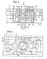
- a faceplate-drive rod assembly 10 with a faceplate 12 and a drive rod 14.
- the faceplate 12 is housed in an outer groove step 16 and the drive rod 14 in an inner groove step 18 of a stepped groove of a casement.
- the drive rod 14 is on the faceplate 12 in the longitudinal direction, ie parallel to the plane of the drawing in FIG. 1 guided.
- a portal-shaped holding block 20 is attached to the faceplate 12.
- This holding block 20 consists of a yoke 20a and two legs 20b.
- the legs 20b pass through an elongated hole 14a of the drive rod 14 and have rivets 20c at their upper ends, which are riveted to the faceplate 12.
- a blocking element block 22 is connected to the legs 20b of the portal 20 via predetermined breaking points 24.
- the blocking element block 22 comprises the actual blocking element 26 which, according to FIG. 1, lies in the plane of the drive rod 14 and, as can be seen from FIG. 3, engages in blocking recesses 14b on the longitudinal edges of the elongated hole 14a. As a result, the drive rod 14 is immovably locked relative to the faceplate 12.
- the locking element block 22 further comprises an upward extension 28 which is U-shaped with legs 28a and a web 28b.
- the blocking element block 22 is designed with a passage 22a for a fastening screw 30.
- the yoke 20a of the holding block also has a passage 20d in alignment with the passage 22a.
- the extension 28 passes through a hole 12a in the faceplate 12. In the position shown in FIG. 1, the extension 28 extends beyond the outside of the faceplate 12.
- the passage 22a has a conical stop surface 22b for a screw head at its upper outlet. If the fastening screw 30 is attached, it penetrates into the groove base 19. As soon as the fastening screw 30 hits the stop surface 22b with its head and is screwed in further, the predetermined breaking points 24 are broken, so that the blocking element block 22 is now inevitably taken down by the screw head in FIG. 1 until the blocking element 26 hits a contact surface 20e of the yoke. As soon as the blocking element 26 stands on the contact surface 20e, the upper end surface of the web 28b is flush with the top or outside of the face plate rail 12.
- the legs 20b are tapered in the area of the elongated hole 14a, so that support surfaces 20g are formed which secure the drive rod on the faceplate 12.
- the tightening force of the fastening screw 30 is introduced into the groove base 19 via the blocking element block 22 and the yoke 20a. It should be noted here, however, that it is not absolutely necessary for the yoke 20a to bear against the groove base 19; If such a system is not present, the tightening force of the fastening screw 30 is introduced into the faceplate 12 via the blocking element block 22 and the portal 20 and is removed on the outer groove step 16. Such an embodiment would have the advantage that a D oppelpassung on the groove bottom 19 on the one hand and the outer slot step 16 is on the other hand avoided.
- FIG. 5 shows that the hole 12a has a circular outline and the locking element block 22 also has a substantially circular outline, the flats 28c recognizable in FIG. 5 continuing into the area of the actual locking element and abutting the bottom of the locking recesses 14b .
- the protrusion of the extension 28 clearly shows the position at which the fastening screw that loosens the assembly lock is to be placed. This ensures that when the unit hits the window, this fastening screw is tightened last, that is, the securing is maintained until it is fully assembled. This increases the security for the correct combination of related units.
Landscapes
- Operating, Guiding And Securing Of Roll- Type Closing Members (AREA)
- Connection Of Plates (AREA)
- Pinball Game Machines (AREA)
- Types And Forms Of Lifts (AREA)
- Tents Or Canopies (AREA)
- Vehicle Step Arrangements And Article Storage (AREA)
- Power-Operated Mechanisms For Wings (AREA)
- Holders For Apparel And Elements Relating To Apparel (AREA)
- Vehicle Body Suspensions (AREA)
- Forklifts And Lifting Vehicles (AREA)
- Platform Screen Doors And Railroad Systems (AREA)
- Jib Cranes (AREA)
- Specific Sealing Or Ventilating Devices For Doors And Windows (AREA)
Priority Applications (1)
| Application Number | Priority Date | Filing Date | Title |
|---|---|---|---|
| AT86116859T ATE63360T1 (de) | 1986-01-09 | 1986-12-04 | Stulpschienen-treibstangen-baueinheit. |
Applications Claiming Priority (2)
| Application Number | Priority Date | Filing Date | Title |
|---|---|---|---|
| DE19863600435 DE3600435A1 (de) | 1986-01-09 | 1986-01-09 | Stulpschienen-treibstangen-baueinheit |
| DE3600435 | 1986-01-09 |
Publications (3)
| Publication Number | Publication Date |
|---|---|
| EP0228594A2 true EP0228594A2 (fr) | 1987-07-15 |
| EP0228594A3 EP0228594A3 (en) | 1989-02-01 |
| EP0228594B1 EP0228594B1 (fr) | 1991-05-08 |
Family
ID=6291574
Family Applications (1)
| Application Number | Title | Priority Date | Filing Date |
|---|---|---|---|
| EP86116859A Expired - Lifetime EP0228594B1 (fr) | 1986-01-09 | 1986-12-04 | Ensemble têtière-tiges d'actionnement |
Country Status (4)
| Country | Link |
|---|---|
| EP (1) | EP0228594B1 (fr) |
| AT (1) | ATE63360T1 (fr) |
| DE (2) | DE3600435A1 (fr) |
| NO (1) | NO870025L (fr) |
Cited By (6)
| Publication number | Priority date | Publication date | Assignee | Title |
|---|---|---|---|---|
| EP0919683A1 (fr) * | 1997-12-01 | 1999-06-02 | FERCO INTERNATIONAL Ferrures et Serrures de Bâtiment, Société Anonyme | Ferrure du type gâche, support d'articulation ou autre, pour porte, fenêtre ou analogue |
| EP1004733A1 (fr) * | 1998-11-28 | 2000-05-31 | Siegenia-Frank Kg | Dispositif d'arrêt à ciseaux |
| FR2786803A1 (fr) * | 1998-12-08 | 2000-06-09 | Ferco Int Usine Ferrures | Ferrure de verrouillage de type cremone |
| EP1002913A3 (fr) * | 1998-11-20 | 2001-07-11 | Björkboda Las Oy Ab | Procédé d' assemblage de serrure |
| EP1099819A3 (fr) * | 1999-11-12 | 2002-12-18 | Roto Frank Ag | Ensemble de ferrure pour montage sur une fenêtre, une porte, ou similaire et procédé de fabrication d'un tel ensemble |
| DE10158360A1 (de) * | 2001-11-28 | 2003-06-12 | Winkhaus Fa August | Beschlagteil |
Families Citing this family (1)
| Publication number | Priority date | Publication date | Assignee | Title |
|---|---|---|---|---|
| DE3743608A1 (de) * | 1987-12-22 | 1989-07-06 | Mayer & Co | Treibstangenbeschlag fuer fenster, tueren und dergleichen |
Family Cites Families (3)
| Publication number | Priority date | Publication date | Assignee | Title |
|---|---|---|---|---|
| DE2313690C2 (de) * | 1973-03-20 | 1987-11-12 | Siegenia-Frank Kg, 5900 Siegen | Treibstangenbeschlag für Fenster, Türen od.dgl |
| DE3240452C3 (de) * | 1982-11-02 | 1996-03-21 | Winkhaus Fa August | Treibstangenbeschlag für Fenster, Türen o. dgl. |
| DE8323365U1 (de) * | 1983-08-13 | 1983-11-24 | Siegenia-Frank Kg, 5900 Siegen | Treibstangenbeschlag fuer fenster, tueren od. dgl. |
-
1986
- 1986-01-09 DE DE19863600435 patent/DE3600435A1/de active Granted
- 1986-12-04 EP EP86116859A patent/EP0228594B1/fr not_active Expired - Lifetime
- 1986-12-04 AT AT86116859T patent/ATE63360T1/de not_active IP Right Cessation
- 1986-12-04 DE DE8686116859T patent/DE3679166D1/de not_active Expired - Fee Related
-
1987
- 1987-01-05 NO NO870025A patent/NO870025L/no unknown
Cited By (10)
| Publication number | Priority date | Publication date | Assignee | Title |
|---|---|---|---|---|
| EP0919683A1 (fr) * | 1997-12-01 | 1999-06-02 | FERCO INTERNATIONAL Ferrures et Serrures de Bâtiment, Société Anonyme | Ferrure du type gâche, support d'articulation ou autre, pour porte, fenêtre ou analogue |
| FR2771768A1 (fr) * | 1997-12-01 | 1999-06-04 | Ferco Int Usine Ferrures | Ferrure du type gache, support d'articulation ou autre comportant des moyens de positionnement par rapport a une rainure en feuillure d'un cadre dormant et/ou de chassis ouvrant de porte, fenetre ou analogue |
| EP1002913A3 (fr) * | 1998-11-20 | 2001-07-11 | Björkboda Las Oy Ab | Procédé d' assemblage de serrure |
| CZ298091B6 (cs) * | 1998-11-20 | 2007-06-20 | Björkboda Las Oy AB | Zpusob výroby provozních soucástí pro zámek, mechanismus provozních soucástí pro skrínku zámku a zámek pro dvere |
| EP1004733A1 (fr) * | 1998-11-28 | 2000-05-31 | Siegenia-Frank Kg | Dispositif d'arrêt à ciseaux |
| FR2786803A1 (fr) * | 1998-12-08 | 2000-06-09 | Ferco Int Usine Ferrures | Ferrure de verrouillage de type cremone |
| EP1008710A1 (fr) * | 1998-12-08 | 2000-06-14 | FERCO INTERNATIONAL Ferrures et Serrures de Bâtiment, Société Anonyme | Ferrure de verrouillage du type crémone |
| EP1099819A3 (fr) * | 1999-11-12 | 2002-12-18 | Roto Frank Ag | Ensemble de ferrure pour montage sur une fenêtre, une porte, ou similaire et procédé de fabrication d'un tel ensemble |
| DE10158360A1 (de) * | 2001-11-28 | 2003-06-12 | Winkhaus Fa August | Beschlagteil |
| DE10158360B4 (de) * | 2001-11-28 | 2014-11-27 | Aug. Winkhaus Gmbh & Co. Kg | Beschlagteil |
Also Published As
| Publication number | Publication date |
|---|---|
| DE3600435C2 (fr) | 1993-02-18 |
| DE3600435A1 (de) | 1987-07-16 |
| EP0228594A3 (en) | 1989-02-01 |
| NO870025D0 (no) | 1987-01-05 |
| DE3679166D1 (de) | 1991-06-13 |
| EP0228594B1 (fr) | 1991-05-08 |
| ATE63360T1 (de) | 1991-05-15 |
| NO870025L (no) | 1987-07-10 |
Similar Documents
| Publication | Publication Date | Title |
|---|---|---|
| EP0223871B1 (fr) | Charnière ouvrant à 180 degrés | |
| EP0171695A1 (fr) | Ecran de douche | |
| EP0440987B2 (fr) | Crémone | |
| DE3605434C2 (de) | Befestigung für ein mit einem Türfeststeller baulich vereinigtes Türscharnier | |
| EP0228594B1 (fr) | Ensemble têtière-tiges d'actionnement | |
| EP1093735A1 (fr) | Glissière pour guidage de tiroirs avec dispositif de fixation et de réglage en hauteur | |
| EP0160196A1 (fr) | Serrure d'assemblage | |
| DE8710534U1 (de) | Profilschließzylinder mit Axialsicherung | |
| EP0748912A1 (fr) | Fenêtre, porte ou similaire | |
| EP0665350B1 (fr) | Dispositif pour le montage d'un carter-support | |
| EP2304148B1 (fr) | Système de bande | |
| DE8702415U1 (de) | Treibstangengetriebe für Fenster, Türen od.dgl. | |
| DE3151224A1 (de) | Vorrichtung zur befestigung eines getriebes an einem rahmen von fenstern, tueren oder dergleichen | |
| EP2369106B1 (fr) | Verrouillage pour un vantail de porte | |
| EP0733761B1 (fr) | Cadre de battant | |
| DE3308319A1 (de) | Auf einem tuerfluegel oder dergleichen zu befestigendes schloss | |
| EP0730074B1 (fr) | Ferrure pour champ de porte d'un battant semi-fixe de portes à deux battants | |
| DE4117014C2 (de) | Scharnier | |
| EP0158069B1 (fr) | Dispositif de fermeture et de verrouillage pour une porte ou analogue | |
| DE29600891U1 (de) | Sicherungseinrichtung | |
| DE3801234A1 (de) | Profilschliesszylinder | |
| CH656915A5 (de) | Vorrichtung zur kupplung senkrecht zueinander verlaufender treibstangen. | |
| DE10015095A1 (de) | Verriegelungsvorrichtung für einen Türflügel | |
| DE3126072A1 (de) | Klemmeinrichtung zur befestigung von beschlaegeteilen | |
| DE7121021U (de) | Treibstangenbeschlag |
Legal Events
| Date | Code | Title | Description |
|---|---|---|---|
| PUAI | Public reference made under article 153(3) epc to a published international application that has entered the european phase |
Free format text: ORIGINAL CODE: 0009012 |
|
| AK | Designated contracting states |
Kind code of ref document: A2 Designated state(s): AT DE FR GB SE |
|
| PUAL | Search report despatched |
Free format text: ORIGINAL CODE: 0009013 |
|
| AK | Designated contracting states |
Kind code of ref document: A3 Designated state(s): AT DE FR GB SE |
|
| 17P | Request for examination filed |
Effective date: 19890424 |
|
| 17Q | First examination report despatched |
Effective date: 19900911 |
|
| GRAA | (expected) grant |
Free format text: ORIGINAL CODE: 0009210 |
|
| AK | Designated contracting states |
Kind code of ref document: B1 Designated state(s): AT DE FR GB SE |
|
| REF | Corresponds to: |
Ref document number: 63360 Country of ref document: AT Date of ref document: 19910515 Kind code of ref document: T |
|
| REF | Corresponds to: |
Ref document number: 3679166 Country of ref document: DE Date of ref document: 19910613 |
|
| GBT | Gb: translation of ep patent filed (gb section 77(6)(a)/1977) | ||
| ET | Fr: translation filed | ||
| PLBI | Opposition filed |
Free format text: ORIGINAL CODE: 0009260 |
|
| 26 | Opposition filed |
Opponent name: SIEGENIA-FRANK KG Effective date: 19920201 |
|
| PLBN | Opposition rejected |
Free format text: ORIGINAL CODE: 0009273 |
|
| STAA | Information on the status of an ep patent application or granted ep patent |
Free format text: STATUS: OPPOSITION REJECTED |
|
| 27O | Opposition rejected |
Effective date: 19930710 |
|
| EAL | Se: european patent in force in sweden |
Ref document number: 86116859.9 |
|
| REG | Reference to a national code |
Ref country code: GB Ref legal event code: IF02 |
|
| PGFP | Annual fee paid to national office [announced via postgrant information from national office to epo] |
Ref country code: GB Payment date: 20031124 Year of fee payment: 18 |
|
| PGFP | Annual fee paid to national office [announced via postgrant information from national office to epo] |
Ref country code: FR Payment date: 20031217 Year of fee payment: 18 |
|
| PGFP | Annual fee paid to national office [announced via postgrant information from national office to epo] |
Ref country code: AT Payment date: 20031219 Year of fee payment: 18 |
|
| PGFP | Annual fee paid to national office [announced via postgrant information from national office to epo] |
Ref country code: SE Payment date: 20031222 Year of fee payment: 18 |
|
| PGFP | Annual fee paid to national office [announced via postgrant information from national office to epo] |
Ref country code: DE Payment date: 20040112 Year of fee payment: 18 |
|
| PG25 | Lapsed in a contracting state [announced via postgrant information from national office to epo] |
Ref country code: GB Free format text: LAPSE BECAUSE OF NON-PAYMENT OF DUE FEES Effective date: 20041204 Ref country code: AT Free format text: LAPSE BECAUSE OF NON-PAYMENT OF DUE FEES Effective date: 20041204 |
|
| PG25 | Lapsed in a contracting state [announced via postgrant information from national office to epo] |
Ref country code: SE Free format text: LAPSE BECAUSE OF NON-PAYMENT OF DUE FEES Effective date: 20041205 |
|
| PG25 | Lapsed in a contracting state [announced via postgrant information from national office to epo] |
Ref country code: DE Free format text: LAPSE BECAUSE OF NON-PAYMENT OF DUE FEES Effective date: 20050701 |
|
| GBPC | Gb: european patent ceased through non-payment of renewal fee |
Effective date: 20041204 |
|
| EUG | Se: european patent has lapsed | ||
| PG25 | Lapsed in a contracting state [announced via postgrant information from national office to epo] |
Ref country code: FR Free format text: LAPSE BECAUSE OF NON-PAYMENT OF DUE FEES Effective date: 20050831 |
|
| REG | Reference to a national code |
Ref country code: FR Ref legal event code: ST |