EP0733761B1 - Cadre de battant - Google Patents
Cadre de battant Download PDFInfo
- Publication number
- EP0733761B1 EP0733761B1 EP96103709A EP96103709A EP0733761B1 EP 0733761 B1 EP0733761 B1 EP 0733761B1 EP 96103709 A EP96103709 A EP 96103709A EP 96103709 A EP96103709 A EP 96103709A EP 0733761 B1 EP0733761 B1 EP 0733761B1
- Authority
- EP
- European Patent Office
- Prior art keywords
- mounting groove
- retaining plate
- frame according
- mushroom
- casement
- Prior art date
- Legal status (The legal status is an assumption and is not a legal conclusion. Google has not performed a legal analysis and makes no representation as to the accuracy of the status listed.)
- Expired - Lifetime
Links
- 239000000463 material Substances 0.000 claims description 5
- 235000001674 Agaricus brunnescens Nutrition 0.000 abstract description 28
- 230000008878 coupling Effects 0.000 description 3
- 238000010168 coupling process Methods 0.000 description 3
- 238000005859 coupling reaction Methods 0.000 description 3
- 238000004873 anchoring Methods 0.000 description 2
- 210000000078 claw Anatomy 0.000 description 2
- 230000006378 damage Effects 0.000 description 2
- 238000003780 insertion Methods 0.000 description 2
- 230000037431 insertion Effects 0.000 description 2
- 230000000694 effects Effects 0.000 description 1
- 239000011521 glass Substances 0.000 description 1
- 238000003801 milling Methods 0.000 description 1
- 230000002028 premature Effects 0.000 description 1
- 239000002023 wood Substances 0.000 description 1
Images
Classifications
-
- E—FIXED CONSTRUCTIONS
- E05—LOCKS; KEYS; WINDOW OR DOOR FITTINGS; SAFES
- E05C—BOLTS OR FASTENING DEVICES FOR WINGS, SPECIALLY FOR DOORS OR WINDOWS
- E05C9/00—Arrangements of simultaneously actuated bolts or other securing devices at well-separated positions on the same wing
- E05C9/004—Faceplates ; Fixing the faceplates to the wing
-
- E—FIXED CONSTRUCTIONS
- E05—LOCKS; KEYS; WINDOW OR DOOR FITTINGS; SAFES
- E05B—LOCKS; ACCESSORIES THEREFOR; HANDCUFFS
- E05B17/00—Accessories in connection with locks
- E05B17/20—Means independent of the locking mechanism for preventing unauthorised opening, e.g. for securing the bolt in the fastening position
- E05B17/2084—Means to prevent forced opening by attack, tampering or jimmying
-
- E—FIXED CONSTRUCTIONS
- E05—LOCKS; KEYS; WINDOW OR DOOR FITTINGS; SAFES
- E05C—BOLTS OR FASTENING DEVICES FOR WINGS, SPECIALLY FOR DOORS OR WINDOWS
- E05C9/00—Arrangements of simultaneously actuated bolts or other securing devices at well-separated positions on the same wing
- E05C9/18—Details of fastening means or of fixed retaining means for the ends of bars
- E05C9/1825—Fastening means
- E05C9/1833—Fastening means performing sliding movements
- E05C9/185—Fastening means performing sliding movements parallel with actuating bar
Definitions
- the invention relates to a casement frame with a recessed undercut fitting groove for receiving the cover rail and drive rod of a window fitting, the drive rod engaging behind an associated striker on the frame by means of a mushroom button.
- a sash frame is known from EP 628 691.
- guided deflection devices are located in the corner areas, e.g. elastic springs, with the help of which the adjoining ends of the fittings arriving there are coupled.
- the advantage of the invention is that the position of the mushroom button on the wing is kept as long as possible when trying to break open.
- the securing plate forms an anchoring of the drive rod on the sash frame, which interacts with the anchoring of the mushroom button on the associated striker and in that way an essentially rigid connection is created between the frame and the sash frame.
- the mushroom button engages behind its associated locking piece and the locking plate the projection of the fitting groove. While the striker is attached to the frame and the securing plate to the casement, a break-proof connection between casement and frame is created in this way, which can only be destroyed under extreme force. In this case, either the rear zone of the mushroom button on the striker or the rear zone of the locking plate in the hardware groove would have to be broken open. By appropriate dimensioning, however, the areas behind each mushroom button / striker and locking plate / hardware groove can be designed so stably that premature destruction of one of the two engagement zones is effectively countered.
- the invention can be implemented in various ways.
- the securing plate On the one hand, it is conceivable to firmly connect the securing plate to the drive rod and with play within the hardware groove. In this case, the securing plate also performs the longitudinal back and forth movement of the drive rod, but in the event of an attempt to break open, it nevertheless acts as a safeguard against the fitting being pulled out of the fitting groove. It is preferably placed directly on the mushroom bolt, so that an unbreakable, tensile connection between the frame and sash is created.
- the securing plate can also be firmly connected to the cover rail, preferably by means of a rigid bolt.
- the rigid bolt break through the drive rod in the region of an elongated hole, so that the drive rod can move freely.
- the locking plate according to this invention in the end area of the respective fitting, there is the further advantage of securing the fitting on the sash frame at the corner.
- the sash frame corner areas which are at great risk of burglary can be reliably secured in this way.
- the rear locking plate can be made so stable by the arrangement in the local area of the mushroom button or immediately next to it that the entire fitting only has to be held in the end area and is still secured against break-in.
- the entry opening for the securing plate in the fitting groove at the end of the frame spar offers the additional advantage of simple fitting of the fitting.
- the securing plate can also be rotatable with an essentially rectangular plan. Then the locking plate could be inserted into the fitting groove in the appropriate rotational position with the wide rectangle side parallel to the longitudinal direction of the fitting groove and then turned so far that the wide rectangle side is then perpendicular to the lengthwise direction of the fitting and engages behind the projection of the fitting groove.
- the entry opening is formed by the hardware groove itself.
- an insertion opening for the securing plate be provided in the area of the miter joint of two mutually abutting frame bars (e.g. by milling). This has the advantage that there is always a precisely defined position of the inlet opening, but this has no effect on the desired strength.
- the assembly can be simplified in that the securing plate is non-rotatably rigidly connected to the drive rod or cover rail, so that the appropriately designed window fitting is simply inserted into the entry opening of the fitting groove and moved longitudinally.
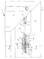
- FIG. 2 The figures show a casement, as is known for example for windows or doors.
- sash 1 consists of frame spars 2, 3 which are assembled at right angles in the area of miter points 4.
- frame spars are usually made of plastic profiles, but without restricting the invention to plastic profiles.
- sash frames are also made of wood.
- wooden frames of this type have become known in which the fitting groove 5 (see FIG. 2) consists of a plastic insert which is screwed to the material of the casement.
- the fitting groove 5 forms a longitudinal material recess from the casement.
- the fitting groove 5 has two mutually opposite projections 14, which define the narrowest cross section of the fitting groove 5.
- the hardware groove extends behind the projections and thus forms an undercut area.
- the fitting groove 5 serves to receive a window fitting 6.
- a window fitting 6 consists of a cover rail 7 and a drive rod 8 which is guided longitudinally thereon.
- the cover rail 7 is usually fastened by means of corresponding elongated holes in the drive rod 8 at the base of the fitting groove 5 screwed and held opposite the casement.
- so-called mushroom button 9 is firmly connected to the drive rod 8. Mushroom buttons can also be provided in pairs (see EP 0 628 691), namely a mushroom button for the closed position and a mushroom button for the tilting position of the casement.
- the associated striker 10 has corresponding longitudinal recesses into which the mushroom buttons enter with their stem area, so that the enlarged areas of the mushroom buttons engage behind these insertion slots and thus prevent the sash from being levered out.
- the cover rail 7 can be fixed in the fitting groove 5 by means of suitable screws.
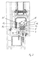
- cover rail 7 and drive rod 8 by means of a projection 14 of the fitting groove 5 engaging locking plate 13 are held on the casement and that the fitting groove 5 has an entry opening 20 for the locking plate 13 lying outside the holding area 23.
- the securing plate 13 is only provided in the mushroom button area 12.
- the enlarged area 15 of the fitting groove 5 receives the securing plate 13, the width 16 of which is greater than the width 15 of the fitting groove 5 which is reduced by the projections 14.
- the securing plate 13 rests firmly against the projections 14 and thus prevents the window fitting 6 from being pulled out in the corner area of the window which is sensitive to break-open.
- the securing plate 13 can be firmly connected to the drive rod 8. It then makes the longitudinal movement of the drive rod 8 within the enlarged area 15 of the fitting groove 5 and is for this purpose mounted with play in the longitudinal direction within the fitting groove 5.
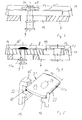
- 4 shows that the securing plate 13 is firmly connected to the cover rail 7 by means of bolts 17.
- the bolt 17 breaks through the drive rod 8 in the region of an elongated hole 19, so that the drive rod 8 can move freely from the fastening of the securing plate 13.
- This variant offers the advantage that to break out the window fitting 6 additional force must be used to destroy the cover rail together with the drive rod.
- the main advantage of this design is that the cover rail and drive rod are pressed against each other in the event of a break-open attempt and practically form an indestructible unit. This unit can practically only be broken open by impossible destruction of the bolts 17, 17a for the securing plate or mushroom button.
- the bolt 17 is mounted with its bolt head 18 in the locking plate 13 in a countersink 24, so that the top of the locking plate 13 is guided in the height direction to the fitting groove with play, which enables smoothness and smoothness.
- FIG. 1 shows that the entry opening 20 for the securing plate 13 is created at the end of the frame spar 2 by a material recess.
- the inlet opening 20 is arranged in the area of the miter point 4, but without restricting the invention. For this purpose, it is only necessary to mill the miter area 4 where the fitting grooves of the frame spars 2, 3 meet. The entry opening 20 for the window fitting 6 according to the invention thus inevitably results at the end of the frame spar 2.
- FIG. 5 shows a securing plate 13, which is equipped on two of its opposite longitudinal edges 21 with teeth 22 pointing in the direction of the projection 14.
- the securing plate 13 claws behind the projection 14 when attempting to break open and thus achieves an additional counterforce which counteracts the breaking direction.
- the securing plate 13 can also engage behind the entire fitting groove 5.
- it can be supported, for example, on the inside of the frame behind the bottom 25 of the fitting groove 5.
- the bottom 25 then forms a technically equivalent means for the projections 14 of the fitting groove 5.
Landscapes
- Engineering & Computer Science (AREA)
- Mechanical Engineering (AREA)
- Load-Engaging Elements For Cranes (AREA)
- Power-Operated Mechanisms For Wings (AREA)
- Door And Window Frames Mounted To Openings (AREA)
- Wing Frames And Configurations (AREA)
- Specific Sealing Or Ventilating Devices For Doors And Windows (AREA)
- Window Of Vehicle (AREA)
- Joining Of Corner Units Of Frames Or Wings (AREA)
Claims (9)
- Châssis de battant (1) comportant une rainure de ferrure (5) contre-dépouillée grâce à une saillie (14) et destinée à recevoir le rail de recouvrement (7) et la tringle de commande (8) d'une ferrure de fenêtre (6), la tringle de commande (8) venant en prise derrière un élément de fermeture associé (10) du dormant (11) grâce à un bouton en forme de champignon (9), caractérisé en ce que le rail de recouvrement (7) et la tringle de commande (8) sont retenus simplement dans la zone (12) du bouton en forme de champignon à l'aide d'une plaque d'arrêt (13) qui vient en prise derrière la saillie (14) de la rainure de ferrure (5), et en ce que la rainure de ferrure (5) comporte pour la plaque d'arrêt (13) une ouverture d'entrée (20) située à l'extérieur de la zone de retenue (23).
- Châssis de battant selon la revendication 1, caractérisé en ce que la plaque d'arrêt (13) est solidaire de la tringle de commande (8) et est montée à l'intérieur de la rainure de ferrure (5) avec du jeu dans le sens longitudinal.
- Châssis de battant selon la revendication 1, caractérisé en ce que la plaque d'arrêt (13) est solidaire du rail de recouvrement (7) grâce à la tige (17), et en ce que la tige (17) traverse la tringle de commande (8) dans la zone d'un trou oblong (19).
- Châssis de battant selon l'une des revendications 1 à 3, caractérisé en ce que la plaque d'arrêt (13) est disposée, avec le bouton en forme de champignon (9) et l'élément de fermeture (10), dans la zone d'extrémité de l'élément de châssis (2) correspondant.
- Châssis de battant selon la revendication 4, caractérisé en ce que la ferrure de fenêtre (6) se termine du côté de l'extrémité de l'élément de châssis (2) et en ce que l'extrémité libre de la ferrure de fenêtre (6) est retenue à cet endroit à l'aide de la plaque d'arrêt (13).
- Châssis de battant selon l'une des revendications 1 à 5, caractérisé en ce que l'ouverture d'entrée (20) est réalisée grâce à un creux de matériau, transversal par rapport au sens longitudinal de la rainure de ferrure (5), à partir de la saillie (14) de celle-ci.
- Châssis de battant selon la revendications 6, caractérisé en ce que l'ouverture d'entrée (20) se trouve du côté de l'extrémité de l'élément de châssis (2) et de préférence dans la zone de l'onglet (4).
- Châssis de battant selon l'une des revendications 1 à 7, caractérisé en ce que la plaque d'arrêt (13) est reliée, immobile en rotation, à la tringle de commande (8) ou au rail de recouvrement (7) et présente une largeur (16) qui correspond à la largeur intérieure de la zone élargie (15) de la rainure de ferrure (5).
- Châssis de battant selon l'une des revendications 1 à 8, caractérisé en ce que la plaque d'arrêt (13) est équipée, sur ses bords longitudinaux latéraux (21) tournés vers la saillie (14) de la rainure de ferrure (5), d'une denture qui pénètre dans la saillie (14).
Applications Claiming Priority (2)
| Application Number | Priority Date | Filing Date | Title |
|---|---|---|---|
| DE29504824U DE29504824U1 (de) | 1995-03-22 | 1995-03-22 | Flügelrahmen |
| DE29504824U | 1995-03-22 |
Publications (3)
| Publication Number | Publication Date |
|---|---|
| EP0733761A2 EP0733761A2 (fr) | 1996-09-25 |
| EP0733761A3 EP0733761A3 (fr) | 1996-12-04 |
| EP0733761B1 true EP0733761B1 (fr) | 1997-08-13 |
Family
ID=8005679
Family Applications (1)
| Application Number | Title | Priority Date | Filing Date |
|---|---|---|---|
| EP96103709A Expired - Lifetime EP0733761B1 (fr) | 1995-03-22 | 1996-03-09 | Cadre de battant |
Country Status (5)
| Country | Link |
|---|---|
| EP (1) | EP0733761B1 (fr) |
| AT (1) | ATE156887T1 (fr) |
| DE (2) | DE29504824U1 (fr) |
| DK (1) | DK0733761T3 (fr) |
| ES (1) | ES2105906T3 (fr) |
Families Citing this family (4)
| Publication number | Priority date | Publication date | Assignee | Title |
|---|---|---|---|---|
| DE19739407C2 (de) * | 1997-09-09 | 2001-05-17 | Pax Gmbh | Fenster/Tür |
| DE102008054614A1 (de) * | 2008-12-15 | 2010-06-17 | Aug. Winkhaus Gmbh & Co. Kg | Fenster mit einem gegen einen Rahmen schwenkbaren Flügel |
| DE102013100133B4 (de) | 2013-01-08 | 2014-10-16 | Pax Ag | Rahmenhohlprofil für einen Flügelrahmen eines Fensters oder einer Tür |
| CN108639308A (zh) * | 2018-05-11 | 2018-10-12 | 南京航天猎鹰飞行器技术有限公司 | 一种用于固定翼飞行器的机翼拆装机构 |
Family Cites Families (10)
| Publication number | Priority date | Publication date | Assignee | Title |
|---|---|---|---|---|
| DE7838570U1 (de) * | 1978-12-27 | 1979-04-12 | Siegenia-Frank Kg, 5900 Siegen | Fenster, tuer o.dgl. aus kunststoff- profilen |
| DE2931580A1 (de) * | 1979-08-03 | 1981-02-19 | Weidtmann Wilhelm Kg | Befestigungsvorrichtung fuer treibstangenbeschlaege von fenstern, tueren o.dgl. |
| AT367848B (de) * | 1980-02-18 | 1982-08-10 | Mayer & Co Riegel Beschlag | Vorrichtung zur befestigung von fenster- oder tuer-beschlagteilen in einer hinterschnittenen profil- nut |
| AT366755B (de) * | 1980-10-14 | 1982-05-10 | Lapp Finze Ag | Klemmeinrichtung zur befestigung von beschlaegeteilen |
| DE3101393A1 (de) * | 1981-01-17 | 1982-09-02 | SCHÜCO Heinz Schürmann GmbH & Co, 4800 Bielefeld | "mit einem stulpschienenbeschlag ausgeruesteter tuer- oder fensterfluegel" |
| DE8323365U1 (de) * | 1983-08-13 | 1983-11-24 | Siegenia-Frank Kg, 5900 Siegen | Treibstangenbeschlag fuer fenster, tueren od. dgl. |
| DE3621419A1 (de) * | 1986-06-26 | 1988-01-07 | Erbsloeh Julius & August | Schliessteil zur einbruchhemmung an fenstern und fenstertueren |
| DE3719011A1 (de) * | 1987-06-06 | 1988-12-22 | Bilstein August Gmbh Co Kg | Verriegelungsbeschlag fuer fenster, tueren od. dgl. |
| DE9217229U1 (de) * | 1992-12-17 | 1994-04-28 | Pax Schweikhard GmbH, 55218 Ingelheim | Schubstangenführung an Fenster- oder Türrahmen |
| DE9308472U1 (de) * | 1993-06-07 | 1993-09-02 | Pax Schweikhard GmbH, 55218 Ingelheim | Dreh-Kipp-Beschlag für Fenster, Türen o.dgl. |
-
1995
- 1995-03-22 DE DE29504824U patent/DE29504824U1/de not_active Expired - Lifetime
-
1996
- 1996-03-09 DE DE59600018T patent/DE59600018D1/de not_active Expired - Lifetime
- 1996-03-09 ES ES96103709T patent/ES2105906T3/es not_active Expired - Lifetime
- 1996-03-09 EP EP96103709A patent/EP0733761B1/fr not_active Expired - Lifetime
- 1996-03-09 AT AT96103709T patent/ATE156887T1/de active
- 1996-03-09 DK DK96103709.0T patent/DK0733761T3/da active
Also Published As
| Publication number | Publication date |
|---|---|
| EP0733761A3 (fr) | 1996-12-04 |
| ATE156887T1 (de) | 1997-08-15 |
| EP0733761A2 (fr) | 1996-09-25 |
| ES2105906T3 (es) | 1997-10-16 |
| DE59600018D1 (de) | 1997-09-18 |
| DE29504824U1 (de) | 1996-08-08 |
| DK0733761T3 (da) | 1998-03-30 |
Similar Documents
| Publication | Publication Date | Title |
|---|---|---|
| EP2048297A2 (fr) | Façade avec montants et traverses de type anti-cambriolage | |
| EP0433623B1 (fr) | Dispositif de verrouillage d'une fenêtre, d'une porte ou similaires | |
| EP0786574A1 (fr) | Ferrure pour verrouiller un battant d'une fênetre ou d'une porte à un dormant | |
| EP0493689B1 (fr) | Tringlerie de commande pour fenêtres, portes ou similaires | |
| EP0761920B1 (fr) | Fenêtre/porte avec battant pivotant et/ou basculant | |
| EP0733761B1 (fr) | Cadre de battant | |
| DE9407569U1 (de) | Einbruchsicherung | |
| EP0573819A2 (fr) | Fenêtre, porte ou similaire avec ferrure pour montage dans des rainures échelonnées des vantaux | |
| EP0748912A1 (fr) | Fenêtre, porte ou similaire | |
| EP0247280B1 (fr) | Dispositif de verrouillage entre l'aile et le cadre fixe de fenêtres, portes ou similaires | |
| EP0844348A1 (fr) | Penture pour portes ou fenêtres | |
| EP0128372B1 (fr) | Dispositif de fermeture d'un battant d'une porte, fenêtre ou similaire à deux battants | |
| DE19745553A1 (de) | Schließvorrichtung | |
| EP0629767B1 (fr) | Cadre de porte ou de fenêtre en bois | |
| DE29615631U1 (de) | Sicherungseinrichtung | |
| DE10229228A1 (de) | Tür-oder Fensterflügelanordnung | |
| EP0158069B2 (fr) | Dispositif de fermeture et de verrouillage pour une porte ou analogue | |
| DE69705077T2 (de) | Scharnier | |
| DE19942563A1 (de) | Einbruchsicherung mit Befestigungsknopf | |
| EP0748911A1 (fr) | Crémone pour le battant d'une fenêtre ou d'une porte | |
| EP0276379B1 (fr) | Dispositif de fixation pour armatures | |
| DE8812938U1 (de) | Beschlag zur Sicherung von beweglichen Flügeln für Fenster, Türen o.dgl. gegen Aufhebeln von außen | |
| DE8901988U1 (de) | Sicherungseinrichtung für Fenster | |
| EP0756054A2 (fr) | Fenêtre, porte ou similaire | |
| EP0765986B1 (fr) | Dispositif de blocage en basculement et de fermeture pour fenêtres, portes, etc. à ouverture basculante et pivotante |
Legal Events
| Date | Code | Title | Description |
|---|---|---|---|
| PUAI | Public reference made under article 153(3) epc to a published international application that has entered the european phase |
Free format text: ORIGINAL CODE: 0009012 |
|
| AK | Designated contracting states |
Kind code of ref document: A2 Designated state(s): AT BE CH DE DK ES FR GB IT LI LU NL PT SE |
|
| PUAL | Search report despatched |
Free format text: ORIGINAL CODE: 0009013 |
|
| AK | Designated contracting states |
Kind code of ref document: A3 Designated state(s): AT BE CH DE DK ES FR GB IT LI LU NL PT SE |
|
| 17P | Request for examination filed |
Effective date: 19961108 |
|
| GRAG | Despatch of communication of intention to grant |
Free format text: ORIGINAL CODE: EPIDOS AGRA |
|
| GRAH | Despatch of communication of intention to grant a patent |
Free format text: ORIGINAL CODE: EPIDOS IGRA |
|
| 17Q | First examination report despatched |
Effective date: 19970123 |
|
| GRAH | Despatch of communication of intention to grant a patent |
Free format text: ORIGINAL CODE: EPIDOS IGRA |
|
| GRAA | (expected) grant |
Free format text: ORIGINAL CODE: 0009210 |
|
| AK | Designated contracting states |
Kind code of ref document: B1 Designated state(s): AT BE CH DE DK ES FR GB IT LI LU NL PT SE |
|
| REF | Corresponds to: |
Ref document number: 156887 Country of ref document: AT Date of ref document: 19970815 Kind code of ref document: T |
|
| REG | Reference to a national code |
Ref country code: CH Ref legal event code: NV Representative=s name: E. BLUM & CO. PATENTANWAELTE Ref country code: CH Ref legal event code: EP |
|
| REF | Corresponds to: |
Ref document number: 59600018 Country of ref document: DE Date of ref document: 19970918 |
|
| ET | Fr: translation filed | ||
| GBT | Gb: translation of ep patent filed (gb section 77(6)(a)/1977) |
Effective date: 19970919 |
|
| REG | Reference to a national code |
Ref country code: ES Ref legal event code: FG2A Ref document number: 2105906 Country of ref document: ES Kind code of ref document: T3 |
|
| ITF | It: translation for a ep patent filed | ||
| REG | Reference to a national code |
Ref country code: PT Ref legal event code: SC4A Free format text: AVAILABILITY OF NATIONAL TRANSLATION Effective date: 19970918 |
|
| REG | Reference to a national code |
Ref country code: DK Ref legal event code: T3 |
|
| PLBE | No opposition filed within time limit |
Free format text: ORIGINAL CODE: 0009261 |
|
| STAA | Information on the status of an ep patent application or granted ep patent |
Free format text: STATUS: NO OPPOSITION FILED WITHIN TIME LIMIT |
|
| 26N | No opposition filed | ||
| PGFP | Annual fee paid to national office [announced via postgrant information from national office to epo] |
Ref country code: SE Payment date: 20000228 Year of fee payment: 5 Ref country code: PT Payment date: 20000228 Year of fee payment: 5 |
|
| PGFP | Annual fee paid to national office [announced via postgrant information from national office to epo] |
Ref country code: DK Payment date: 20000303 Year of fee payment: 5 |
|
| PGFP | Annual fee paid to national office [announced via postgrant information from national office to epo] |
Ref country code: GB Payment date: 20000308 Year of fee payment: 5 |
|
| PGFP | Annual fee paid to national office [announced via postgrant information from national office to epo] |
Ref country code: AT Payment date: 20000314 Year of fee payment: 5 |
|
| PGFP | Annual fee paid to national office [announced via postgrant information from national office to epo] |
Ref country code: ES Payment date: 20000315 Year of fee payment: 5 |
|
| PG25 | Lapsed in a contracting state [announced via postgrant information from national office to epo] |
Ref country code: GB Free format text: LAPSE BECAUSE OF NON-PAYMENT OF DUE FEES Effective date: 20010309 Ref country code: DK Free format text: LAPSE BECAUSE OF NON-PAYMENT OF DUE FEES Effective date: 20010309 Ref country code: AT Free format text: LAPSE BECAUSE OF NON-PAYMENT OF DUE FEES Effective date: 20010309 |
|
| PG25 | Lapsed in a contracting state [announced via postgrant information from national office to epo] |
Ref country code: SE Free format text: LAPSE BECAUSE OF NON-PAYMENT OF DUE FEES Effective date: 20010310 Ref country code: ES Free format text: LAPSE BECAUSE OF NON-PAYMENT OF DUE FEES Effective date: 20010310 |
|
| PG25 | Lapsed in a contracting state [announced via postgrant information from national office to epo] |
Ref country code: PT Free format text: LAPSE BECAUSE OF NON-PAYMENT OF DUE FEES Effective date: 20010930 |
|
| GBPC | Gb: european patent ceased through non-payment of renewal fee |
Effective date: 20010309 |
|
| EUG | Se: european patent has lapsed |
Ref document number: 96103709.0 |
|
| REG | Reference to a national code |
Ref country code: DK Ref legal event code: EBP |
|
| REG | Reference to a national code |
Ref country code: PT Ref legal event code: MM4A Free format text: LAPSE DUE TO NON-PAYMENT OF FEES Effective date: 20010930 |
|
| REG | Reference to a national code |
Ref country code: ES Ref legal event code: FD2A Effective date: 20030203 |
|
| PGFP | Annual fee paid to national office [announced via postgrant information from national office to epo] |
Ref country code: NL Payment date: 20030328 Year of fee payment: 8 |
|
| PGFP | Annual fee paid to national office [announced via postgrant information from national office to epo] |
Ref country code: BE Payment date: 20040315 Year of fee payment: 9 |
|
| PGFP | Annual fee paid to national office [announced via postgrant information from national office to epo] |
Ref country code: LU Payment date: 20040331 Year of fee payment: 9 |
|
| PG25 | Lapsed in a contracting state [announced via postgrant information from national office to epo] |
Ref country code: LU Free format text: LAPSE BECAUSE OF NON-PAYMENT OF DUE FEES Effective date: 20050309 Ref country code: IT Free format text: LAPSE BECAUSE OF NON-PAYMENT OF DUE FEES;WARNING: LAPSES OF ITALIAN PATENTS WITH EFFECTIVE DATE BEFORE 2007 MAY HAVE OCCURRED AT ANY TIME BEFORE 2007. THE CORRECT EFFECTIVE DATE MAY BE DIFFERENT FROM THE ONE RECORDED. Effective date: 20050309 |
|
| PG25 | Lapsed in a contracting state [announced via postgrant information from national office to epo] |
Ref country code: BE Free format text: LAPSE BECAUSE OF NON-PAYMENT OF DUE FEES Effective date: 20050331 |
|
| BERE | Be: lapsed |
Owner name: *PAX G.M.B.H. Effective date: 20050331 |
|
| PG25 | Lapsed in a contracting state [announced via postgrant information from national office to epo] |
Ref country code: NL Free format text: LAPSE BECAUSE OF NON-PAYMENT OF DUE FEES Effective date: 20051001 |
|
| NLV4 | Nl: lapsed or anulled due to non-payment of the annual fee |
Effective date: 20051001 |
|
| REG | Reference to a national code |
Ref country code: CH Ref legal event code: PFA Owner name: PAX GMBH Free format text: PAX GMBH#GEWERBEGEBIET RUESTERBAUM, VORDERER BOEHL 39#D-55218 INGELHEIM (DE) -TRANSFER TO- PAX GMBH#GEWERBEGEBIET RUESTERBAUM, VORDERER BOEHL 39#D-55218 INGELHEIM (DE) |
|
| BERE | Be: lapsed |
Owner name: *PAX G.M.B.H. Effective date: 20050331 |
|
| REG | Reference to a national code |
Ref country code: DE Ref legal event code: R082 Ref document number: 59600018 Country of ref document: DE Representative=s name: MUELLER, JOCHEN, DIPL.-ING., DE Ref country code: DE Ref legal event code: R082 Ref document number: 59600018 Country of ref document: DE Representative=s name: JOCHEN MUELLER, DE |
|
| PGFP | Annual fee paid to national office [announced via postgrant information from national office to epo] |
Ref country code: CH Payment date: 20130522 Year of fee payment: 18 |
|
| PGFP | Annual fee paid to national office [announced via postgrant information from national office to epo] |
Ref country code: DE Payment date: 20140325 Year of fee payment: 19 |
|
| PGFP | Annual fee paid to national office [announced via postgrant information from national office to epo] |
Ref country code: FR Payment date: 20140319 Year of fee payment: 19 |
|
| REG | Reference to a national code |
Ref country code: CH Ref legal event code: PL |
|
| PG25 | Lapsed in a contracting state [announced via postgrant information from national office to epo] |
Ref country code: LI Free format text: LAPSE BECAUSE OF NON-PAYMENT OF DUE FEES Effective date: 20140331 Ref country code: CH Free format text: LAPSE BECAUSE OF NON-PAYMENT OF DUE FEES Effective date: 20140331 |
|
| REG | Reference to a national code |
Ref country code: DE Ref legal event code: R119 Ref document number: 59600018 Country of ref document: DE |
|
| REG | Reference to a national code |
Ref country code: FR Ref legal event code: ST Effective date: 20151130 |
|
| PG25 | Lapsed in a contracting state [announced via postgrant information from national office to epo] |
Ref country code: DE Free format text: LAPSE BECAUSE OF NON-PAYMENT OF DUE FEES Effective date: 20151001 |
|
| PG25 | Lapsed in a contracting state [announced via postgrant information from national office to epo] |
Ref country code: FR Free format text: LAPSE BECAUSE OF NON-PAYMENT OF DUE FEES Effective date: 20150331 |