EP0228628A2 - Pompe de dosage de précision pour des liquides, notamment pour l'usage dans la technologie HPLC - Google Patents
Pompe de dosage de précision pour des liquides, notamment pour l'usage dans la technologie HPLC Download PDFInfo
- Publication number
- EP0228628A2 EP0228628A2 EP86117186A EP86117186A EP0228628A2 EP 0228628 A2 EP0228628 A2 EP 0228628A2 EP 86117186 A EP86117186 A EP 86117186A EP 86117186 A EP86117186 A EP 86117186A EP 0228628 A2 EP0228628 A2 EP 0228628A2
- Authority
- EP
- European Patent Office
- Prior art keywords
- pump head
- valve
- metering pump
- head housing
- valve unit
- Prior art date
- Legal status (The legal status is an assumption and is not a legal conclusion. Google has not performed a legal analysis and makes no representation as to the accuracy of the status listed.)
- Withdrawn
Links
Images


Classifications
-
- F—MECHANICAL ENGINEERING; LIGHTING; HEATING; WEAPONS; BLASTING
- F04—POSITIVE - DISPLACEMENT MACHINES FOR LIQUIDS; PUMPS FOR LIQUIDS OR ELASTIC FLUIDS
- F04B—POSITIVE-DISPLACEMENT MACHINES FOR LIQUIDS; PUMPS
- F04B53/00—Component parts, details or accessories not provided for in, or of interest apart from, groups F04B1/00 - F04B23/00 or F04B39/00 - F04B47/00
- F04B53/10—Valves; Arrangement of valves
- F04B53/108—Valves characterised by the material
-
- F—MECHANICAL ENGINEERING; LIGHTING; HEATING; WEAPONS; BLASTING
- F04—POSITIVE - DISPLACEMENT MACHINES FOR LIQUIDS; PUMPS FOR LIQUIDS OR ELASTIC FLUIDS
- F04B—POSITIVE-DISPLACEMENT MACHINES FOR LIQUIDS; PUMPS
- F04B13/00—Pumps specially modified to deliver fixed or variable measured quantities
-
- F—MECHANICAL ENGINEERING; LIGHTING; HEATING; WEAPONS; BLASTING
- F04—POSITIVE - DISPLACEMENT MACHINES FOR LIQUIDS; PUMPS FOR LIQUIDS OR ELASTIC FLUIDS
- F04B—POSITIVE-DISPLACEMENT MACHINES FOR LIQUIDS; PUMPS
- F04B53/00—Component parts, details or accessories not provided for in, or of interest apart from, groups F04B1/00 - F04B23/00 or F04B39/00 - F04B47/00
- F04B53/007—Cylinder heads
-
- F—MECHANICAL ENGINEERING; LIGHTING; HEATING; WEAPONS; BLASTING
- F04—POSITIVE - DISPLACEMENT MACHINES FOR LIQUIDS; PUMPS FOR LIQUIDS OR ELASTIC FLUIDS
- F04B—POSITIVE-DISPLACEMENT MACHINES FOR LIQUIDS; PUMPS
- F04B53/00—Component parts, details or accessories not provided for in, or of interest apart from, groups F04B1/00 - F04B23/00 or F04B39/00 - F04B47/00
- F04B53/10—Valves; Arrangement of valves
- F04B53/1002—Ball valves
-
- F—MECHANICAL ENGINEERING; LIGHTING; HEATING; WEAPONS; BLASTING
- F04—POSITIVE - DISPLACEMENT MACHINES FOR LIQUIDS; PUMPS FOR LIQUIDS OR ELASTIC FLUIDS
- F04B—POSITIVE-DISPLACEMENT MACHINES FOR LIQUIDS; PUMPS
- F04B53/00—Component parts, details or accessories not provided for in, or of interest apart from, groups F04B1/00 - F04B23/00 or F04B39/00 - F04B47/00
- F04B53/16—Casings; Cylinders; Cylinder liners or heads; Fluid connections
- F04B53/162—Adaptations of cylinders
-
- G—PHYSICS
- G01—MEASURING; TESTING
- G01F—MEASURING VOLUME, VOLUME FLOW, MASS FLOW OR LIQUID LEVEL; METERING BY VOLUME
- G01F11/00—Apparatus requiring external operation adapted at each repeated and identical operation to measure and separate a predetermined volume of fluid or fluent solid material from a supply or container, without regard to weight, and to deliver it
- G01F11/02—Apparatus requiring external operation adapted at each repeated and identical operation to measure and separate a predetermined volume of fluid or fluent solid material from a supply or container, without regard to weight, and to deliver it with measuring chambers which expand or contract during measurement
- G01F11/021—Apparatus requiring external operation adapted at each repeated and identical operation to measure and separate a predetermined volume of fluid or fluent solid material from a supply or container, without regard to weight, and to deliver it with measuring chambers which expand or contract during measurement of the piston type
- G01F11/029—Apparatus requiring external operation adapted at each repeated and identical operation to measure and separate a predetermined volume of fluid or fluent solid material from a supply or container, without regard to weight, and to deliver it with measuring chambers which expand or contract during measurement of the piston type provided with electric controlling means
-
- G—PHYSICS
- G01—MEASURING; TESTING
- G01N—INVESTIGATING OR ANALYSING MATERIALS BY DETERMINING THEIR CHEMICAL OR PHYSICAL PROPERTIES
- G01N30/00—Investigating or analysing materials by separation into components using adsorption, absorption or similar phenomena or using ion-exchange, e.g. chromatography or field flow fractionation
- G01N30/02—Column chromatography
- G01N30/26—Conditioning of the fluid carrier; Flow patterns
- G01N30/28—Control of physical parameters of the fluid carrier
- G01N30/32—Control of physical parameters of the fluid carrier of pressure or speed
- G01N2030/328—Control of physical parameters of the fluid carrier of pressure or speed valves, e.g. check valves of pumps
Definitions
- the invention relates to a fine metering pump for liquids, in particular for use in HPLC technology, with a pump head housing, with at least one pump head sleeve arranged therein, containing a displacement chamber and supply and discharge channels, and with a plunger for each displacement chamber, pump head sleeve (s) and Plungers are made of chemically inert material.
- a pump head liner lining the pump head should consist of a chemically inert material, for example of the plastics polymonochlorotrifluoroethylene (KEL F) or polyvinilidene fluoride (PVDF).
- KEL F polymonochlorotrifluoroethylene
- PVDF polyvinilidene fluoride
- the pump head sleeve can also be made from ceramic material, for example from A1 2 0 3 ceramic, which is polycrystalline.
- the material previously used or proposed for the pump head sleeve is opaque and, for the desired visual control of the conveying process, does not allow an insight into the displacement space.
- the areas of the pump head sleeve that are essential for observing the conveying process are not visible from the outside, but are covered by the pump head housing.
- the possibility of a visual control of the delivery process is of particular importance, since the delivery rate for the pump type considered here, which is used in particular in HPLC analysis technology, ranges from a few ml / min down to a few ⁇ l / min and also there is a trend towards miniaturization in terms of equipment and delivery capacity.
- the invention is therefore based on the object of improving the known fine metering pump in such a way that the delivery process can be visually observed and monitored from the outside.
- the object is achieved in that the material of the pump head sleeve (s) is transparent and that the pump head housing is provided with at least one opening or recess through which the pump head sleeve (s) is (are) visible from the outside.
- the visual accessibility of the pump head sleeve (s) enables the delivery process in the pump's displacement system to be optically recorded and monitored directly.
- the piston movement and the state of the piston seal, the extent of abrasion on the seal and the formation of deposits on the piston can be detected.
- the pump head sleeve (s) from synthetic sapphire (this is monocrystalline A1 2 0 3 ) or monocrystalline zirconium oxide and to polish the surface after shaping by grinding in order to make the pump head sleeve (s) transparent.
- the proposed material allows the pump head sleeve to be subjected to an extremely high delivery pressure; in addition, it is chemically inert without restriction and reliably excludes any contamination, even trace, of the pumped medium, which is important for use in the field of special biochemical analysis with regard to contamination by heavy metal ions and in relation to surface abrasion. From this point of view, the material selection for the pump head sleeve is very specific. It is given independent inventive importance. Furthermore, the exceptional hardness of synthetic sapphire and moncrystalline zirconium oxide results in the advantage of the scratch resistance of the pump head sleeve, which is important for maintaining transparency even during long, rough operation.
- sapphire as a material for the piston is mentioned in German Patent 31 22 091.
- sapphire for this pump component is not comparable to that described above, since it is solely a compressive load on a solidly designed cylindrical body, the choice of synthetic sapphire as the material being based on the highest possible wear resistance.
- a single head displacement system design the pump head housing in the manner of a U-shaped yoke, the pump head sleeve being arranged in its central recess and being visible through the gap formed by the yoke legs.
- a double displacement system with a block-shaped pump head housing to provide this with recesses for receiving the pump head sleeves, with a viewing slot leading to each recess through which the pump head sleeve located in the recess is visible.
- the pump head housing can have receiving bores for cartridge-like valve units, each of which is connected to the supply duct or the discharge duct (s) of a pump head sleeve.
- cartridge-like valve units are connected by small fittings (fitting screw with cutting ring) to a connecting pipeline for the pumped medium. It has been found, however, that such fitting connections tend to leak quickly when they are repeatedly screwed and loosened as a result of progressive plastic deformation on the cutting rings.
- each valve unit is held in the associated bore hole by a mounting element that can be anchored to the pump head housing and is pressed against the pump head sleeve for the purpose of connection to the supply duct or discharge duct.
- a connecting pipe adapter is interposed, which contains an angled conduit which is connected at one end to the valve unit and at the other end to a connecting pipe for the conveying medium, and that the connecting pipe adapter connects the valve unit and the pump head sleeve by means of a Fi reaching through the mounting element Xier screw are pressed together.
- a connecting pipe adapter not only prevents a fitting connection, but also ensures that the rotational movement of the fixing screw is not transmitted to the cartridge-like valve unit. This is important because the peripheral seal at the transition points is achieved by means of flat seals, which ideally should only be preloaded axially to achieve tightness.
- the flat seal (sealing ring made of PTFE compound) of the cartridge-like valve units paired with the pump head sleeve comes to rest on an unpolished, that is to say deliberately left relatively rough, contact area of the pump head sleeve. Twisting the flat gasket during the fixing process on this contact surface would interfere with the desired surface wedging of the two surfaces in the micro range.
- the mounting element for a valve unit can, in a first embodiment, be designed in the manner of a clamp and anchored to the pump head housing in such a way that it engages with projections or offsets provided on its temple ends in grooves located on the pump head housing or engages behind projections on the pump head housing, and that it engages behind the crosspiece of the clamp-like bracket element penetrating fixing screw acts directly on the intermediate connecting tube adapter.
- the mounting element for a valve unit is designed as an L-shaped clamping angle, which consists of a support leg and a fixing leg, that the support leg is provided with an offset, which in a corresponding recess or a slot on the Pump head housing engages, and that the fixing leg on the intermediary between it and the valve unit connecting pipe adapter is seated and is penetrated by the umpenkopfgetude in the P screwed fixing screw, so that the fixing screw acts indirectly on the connecting pipe adapter.
- the power transmission from the fixing leg of the L-shaped clamping bracket to the connecting pipe adapter is advantageously carried out by a pin firmly anchored in the fixing bracket of the clamping bracket with a spherical end or by a ball which is pressed into a blind hole provided in the fixing bracket.
- valve units are made of synthetic sapphire or monocrystalline zirconia made transparent after shaping by polishing, and that the valve balls are made of ribin.
- the pump head housing can be provided with corresponding recesses or inspection holes.
- the transparent valve units as described above and visually accessible from the outside can now be monitored by an optical sensor system, such as a light barrier, which responds to the function of the valve unit, in particular to the lifting of the valve ball from the valve seat.
- This optical monitoring is in keeping with the fact that the valve ball - if it consists of ruby - is of a different color.
- the optical sensor system or the light barriers can be used to obtain the actual value for the actual start of the delivery process in a control circuit by means of which the piston speed is regulated in order to compensate for the influence of the specific compressibility of the liquid to be delivered on the pump efficiency in the displacement space. So far, such an actual value signal has been obtained by continuously measuring the pressure in the displacement space (German patent 31 22 091).
- the piston which is made of synthetic sapphire
- a light source for introducing light in its clamping or its shaft.
- This light source can be a light emitting diode, for example.
- the pump head housing with at least one hole leading to the recess (es) for the pump head sleeve (s), which is used to receive a light source that illuminates the pump head sleeve (s).
- the invention further relates to a fine metering pump for liquids, in particular for use in HPLC technology, with a pump head housing, with at least one pump head bushing arranged therein, containing a displacement chamber and supply and discharge channels, with a plunger for each displacement chamber, and with in receiving bores of the Pump head housing arranged cartridge-like valve units, each of which rests with its one end at the mouth region of the (one) supply channel or discharge channel on the pump head bushing (s).
- the invention is based on the further object of improving the fine metering pump of the type described above in such a way that the above disadvantage is avoided.
- each cartridge-like valve unit there is a connecting pipe adapter which contains an angled conduit which is connected at one end to the valve unit and at its other end to a connecting pipe for the liquid to be conveyed, and that a sealing pressure is exerted on the connecting pipe adapter, by means of which a liquid-tight connection of the valve unit to the pumps head sleeve on the one hand and the connecting tube adapter on the other hand is guaranteed.
- the sealing pressure can be exerted on the connecting pipe adapter by a holding element anchored to the pump head housing by means of a fixing screw provided on the latter.
- the mounting element itself can, in a first embodiment, be designed in the manner of a clamp and anchored to the pump head housing in such a way that it engages with projections or offsets provided on its clamp ends in grooves located on the pump head housing or engages behind projections located on the pump head housing, and that it engages the crossbar of the clamp-like Fixing screw penetrating directly acts on the intermediate connection ear adapter.
- the holding element is designed as an L-shaped clamping angle, which consists of a support leg and a fixing leg, that the support leg is provided with an offset which engages in a corresponding recess or a slot on the pump head housing, and that the fixing leg sits on the connecting pipe adapter interposed between it and the valve unit and is penetrated by the fixing screw screwed into the pump head housing, in such a way that the fixing screw acts indirectly on the connecting pipe adapter.
- the power transmission from the fixing leg of the L-shaped clamping bracket to the connecting tube adapter is expediently carried out by a pin with a crowned end or anchored in the fixing bracket of the clamping bracket by a ball which is pressed into a blind hole provided in the fixing leg.
- a connecting tube adapter in particular in connection with a mounting element and a fixing screw, not only prevents a fitting connection, but also ensures that the rotational movement of the fixing screw is not transmitted to the cartridge-like valve unit.
- This is important because the peripheral seal at the transition points is achieved by means of flat seals, which ideally should only be preloaded axially to achieve tightness.
- the flat seal paired with the pump head sleeve (sealing ring made of PTFE compound) of the cartridge-like valve units comes on an unpolished, i.e. H. deliberately left the rough contact surface of the pump head sleeve. Twisting the flat gasket during the fixing process on this contact surface would interfere with the desired "wedging" of the two surfaces in the micro region under the influence of the prestress applied for the purpose of sealing.
- the invention relates to a fine metering pump for liquids, in particular for use in HPLC technology, with at least two displacement spaces which are connected to valve units via supply and discharge channels, with a piston for each displacement space, of which at least one is always delivering, whereby for Compensation for the influence of the specific compressibility of the pumped medium on the pump efficiency at least one piston carries out a pre-compression stroke before each delivery stroke, with a piston position transmitter, with a feed insert detector, and with a control circuit for the piston drive connected to the piston position transmitter and the feed insert detector for regulating the piston speed.
- Such metering pumps are known, for example again according to German Patent 27 37 062. In the present case, it is not necessary that, as described in German Patent 27 37 062, it is a double-head pump in which both heads are equipped with valve units and therefore work alternately independently.
- the fine metering pump can also be operated with two pump heads, only one of which is equipped with a valve unit and the heads work in series, as described in German Patent 32 03 722.
- Such fine metering pumps aim to achieve a pulsation-free mass flow. This is achieved in that a pre-compression stroke is carried out before each delivery stroke.
- the pre-compression stroke is kinematic, chosen for maximum compressibility and working pressure, on the drive cam for the piston.
- the invention is therefore based on the object of providing a pulsation-free fine metering pump of the type described above, in which a more precise determination of the delivery rate and thus an improved control is possible.
- the object is achieved in that the feeder detector scans at least one outlet valve unit for opening.
- the solution according to the invention can be implemented in that the feed-in detector responds to the lifting of the valve ball of at least one outlet valve from the valve seat.
- a further development can consist in that at least parts of an outlet valve unit are made of transparent material, but the valve ball is of a different color or transparent, and that the feed-in detector is an optical sensor system, such as a light barrier, which responds to the lifting of the valve ball from the valve seat.
- a transparent outlet valve unit not only offers the advantage of being able to be optically scanned, but it also allows, with visual accessibility, the functioning of the valves to be monitored from the outside.
- Transparent sapphire or transparent monocrystalline zirconium oxide are particularly suitable as the material for the parts of a transparent outlet valve unit. These materials are not only transparent, they are also chemically inert and extremely hard without restrictions, which ensures high wear resistance.
- the valve ball can be made from ruby, for example, which is colored. This allows the movement of the valve ball to be detected optically without any problems.
- valve ball of at least one outlet valve unit from ferromagnetic material, preferably from special stainless steel.
- the feeder detector can magnetically detect the movement of the valve ball. This is countered by the use of sapphire or monocrystalline zirconium oxide for the valve peripheral elements, since the materials mentioned are non-magnetic and accordingly have no magnetic shielding effect.
- valve ball from ferromagnetic material and to coat it with a ceramic material, for example with titanium carbide, which is chemically inert and extremely hard.
- the fine metering pump shown in FIGS. 1 and 2 has a pump head housing 1 which is designed in the manner of a U-shaped yoke.
- the yoke legs are labeled 2 and 3.
- the pump head housing 1 and the pump head shield 6 are made of stainless steel or chemically resistant plastic.
- the gap 7 between the yoke legs 2, 3 is designed as a receiving bore that is open towards the sides and serves to receive a cylindrical pump head sleeve 8.
- the pump head sleeve 8 consists of synthetic sapphire (monocrystalline A1 2 0 3 ) or monocrystalline zirconium oxide (Zr0 2 ).
- the raw piece is initially transparent or translucent. However, from this the pump head sleeve to manufacture it has to be ground, which makes it blind. However, it can be made transparent again by subsequent polishing or lapping. Sapphire and m d nocrystalline zirconium oxide are chemically inert and extraordinarily hard and therefore scratch-resistant even during long, rough operation.
- the pump head sleeve 8 contains an axially extending blind hole-shaped displacement space 9, which widens to an annular groove 10 at the opening end.
- a radial inlet channel 11 and a radial outlet channel 12 lead to the bottom of the blind hole of the displacement chamber 9.
- the pump head sleeve has small annular beads 13, 14 surrounding the openings . Furthermore, the annular surfaces surrounding the annular beads 13, 14 have been excluded from polishing and have deliberately been left rough.
- the wall thickness of the pump head sleeve can be chosen relatively small when choosing these materials, despite the high delivery gap required in HPLC technology. For example, it can be between 2-8 mm, preferably 5 mm; however, such a pump head sleeve can withstand delivery pressures of up to 600 bar and above.
- the annular groove 10 serves to receive a spring-supported ring seal 15, the shell of which can be made of PTFE, for example.
- the gap between the two yoke legs 2 and 3 of the pump head housing 1 also serves to receive a piston guide sleeve 16, which can consist of ceramic material, for example sintered A1 2 0 3 and is provided with flushing or drainage connection lines 17.
- a flat seal 18 is inserted between the piston guide sleeve 16 and the pump head sleeve 8.
- the piston guide sleeve 16 is also provided at its end facing away from the pump head sleeve 8 with an annular groove 19 which receives an annular seal 20.
- the piston 21 is clamped in a shaft part 22 which is connected to a drive mechanism (not shown further here).
- the shaft part 22 contains a light-emitting diode 23, which are connected to a voltage source via electrical leads 24.
- the light-emitting diode 23 sends light into the piston 21 made of transparent sapphire, as a result of which the pump head sleeve 8 is illuminated from the inside.
- the two yoke legs 2, 3 of the pump head sleeve 1 are further provided with receiving bores 25, 26 which are perpendicular to the axis of the pump head sleeve 8.
- the receiving bore 25 serves to receive a cartridge-shaped inlet valve unit 27.
- the receiving bore 26 serves to receive a cartridge-shaped outlet valve unit 28.
- Both valve units contain the same components, the arrangement of which differs from one another depending on the inlet or outlet configuration. However, it is sufficient to describe the outlet valve unit 28.
- the outlet valve unit 28 consists of a hollow cylindrical valve cartridge housing 29, which contains a ball guide element 33 with an attached ball stop. A movable one sits in the ball guide element 33 Valve ball 31.
- the ball guide element 33 abuts a valve seat 30 with its open end.
- the closed end of the ball guide element 33 has a cross-slotted or sieve-plate-shaped end as a ball stop.
- Both openings of the valve cartridge housing 29, which receives the valve seat 30 with ball 31 and the ball guide element 33 are closed by sealing rings 32, 34.
- the valve cartridge housing 29, the valve seat 30 and the ball guide element 33 consist of transparent material, preferably of the same as the pump head sleeve 8, for. B. made of synthetic sapphire or monocrystalline zirconium oxide.
- the ball 31 is made of ruby. It is red and therefore clearly distinguishable from the associated parts mentioned above.
- the two sealing rings are made of a PTFE compound.
- the two yoke legs 2, 3 of the pump head housing 1 are provided with transverse slots 53, 54, which make that part of the valve cartridge housing which comprises the ball guide element 33 and in particular the valve seat 30 and the ball 31 visually accessible. As a result, the movement of the ball 31 in the outlet valve unit 28 can be seen.
- the sealing ring 32 is seated on the rough contact surface of the pump head sleeve 8, which surrounds the annular bead 14.
- Clamping brackets 35, 36 are used to fix the cartridge-like valve units 27, 28 in the receiving bores 25, 26. These are provided with bent portions 37, 38 on their bow ends, which form undercut grooves.
- the pump head housing 1 is double T-shaped in a cross-section to the axis of the pump head sleeve 8.
- the two clamps 35, 36 are also with the undercut grooves on the by Double-T cut formed cross webs 39, 40 pushed, the elbows 37, 38 engage behind the cross webs 39, 40.
- clamping brackets 37, 38 have recesses on their inside, of which only the recess 41 on the clamping bracket 35 is visible in FIG. 2.
- Connection tube adapters 42, 43 are inserted into these recesses.
- the connecting pipe adapters 42, 43 contain an angled conduit, which at one end pierces the side of the connecting pipe adapter facing the relevant valve unit and is surrounded by an annular bead, and which is connected at its other end to a connecting pipe for the conveying medium.
- the annular bead is designated 44 and the connecting tube 45.
- the connecting pipe is designated 46 here.
- the flow of the pumped medium at the connection pipe adapter 43 connected to the outlet valve unit is represented by arrows.
- the connecting pipe adapter 43 also shows that an indentation 47 is provided on the side facing away from the associated valve unit 28, into which a spherically shaped pin 48 of an Allen screw 49 or a knurled screw 50 used instead of this can engage.
- the grub screw 49 or the knurled screw 50 are screwed into a continuous threaded hole 51, which is provided in the clamping bracket 36.
- the grub screw 49 and the knurled screw 50 press the connecting pipe adapter 43, the outlet valve unit 28 and the pump head sleeve 8 firmly against one another, such that a leak-free connection between the displacement chamber 9 and the connecting pipe 46 is ensured.
- a hexagon socket is Set screw 51 or a knurled screw 52 is provided.
- the use of hexagon socket screws or knurled screws enables the valve cartridges to be fixed particularly sensitively, which permits peripheral sealing without excessive mechanical pretensioning of the valves relative to the pump head sleeve.
- By interposing the connecting tube adapters locked in the associated clamps it is also achieved that the rotational movement of the fixing screws is not transmitted to the valve cartridges. This is important because the peripheral seal laughing seals at the crossing points by means F is accomplished which are to be optimally biased only axially to achieve tightness.
- the flat seal 32 of the outlet valve unit 28 paired with the pump head sleeve and the corresponding flat seal of the inlet valve unit 27 come to rest on the unpolished, ie deliberately left relatively rough contact surfaces. Twisting the flat seals during the fixing process on these contact surfaces would interfere with the desired surface "wedging" of the two surfaces in the micro region under the influence of the pretension applied for sealing.
- the use of connecting pipe adapters also makes it possible to avoid the previously common small fittings (fitting screw with cutting ring), which tend to leak quickly when tightening and loosening several times due to continuous plastic deformation on the cutting rings.
- the pump head sleeve 8 is visually accessible through the gap between the yoke legs 2, 3 of the pump head housing 1. Since the pump head sleeve 8 is made of transparent material, the piston movements or the delivery process can be observed. In particular that is Occurrence of cavitation and / or air bubbles that get into the displacement space 9 via the suction flow can be seen. The condition of the piston seal, the extent of abrasion on the seal and the formation of deposits on the piston can also be seen.
- valve units 27, 28 can also be visually monitored by the transverse slots 39, 54. Visual monitoring is facilitated by the illumination of the pump head sleeve 8 via the piston 21. Instead of illuminating the piston 21, it is also possible to provide a viewing hole 55 in the curved area of the pump head housing 1 (see FIG. 1), into which a (not shown) ) Light source is plugged in.
- L-shaped clamping angles 100, 101 are provided instead of the clamping bracket. Since the clamping angles 100, 101 are of the same design, only the clamping angle 101 will be explained in more detail.
- This consists of a support leg 102 and a fixing leg 103.
- An offset 104 is provided on the support leg 102, which engages in a slot 105 of the pump head housing, which is also designated 1 here.
- a slot 106 is provided in the fixing leg 103 for receiving the connecting pipe adapter 43, the connecting pipe 41 of which is directed here to the side.
- a pin 107 is anchored in the fixing leg 103, the free end of which is designed spherically. With this crowned end, the pin 107 engages in the recess 38 of the connecting tube adapter 43.
- the clamping takes place here indirectly by means of a fixing screw 108 which passes through a bore 109 in the fixing leg 103 of the clamping bracket 101 and is screwed into a threaded bore 110 of the pump head housing 1.
- 1 and 2 is also new in the embodiment according to FIG. 3, a saddle-like attachment 111 which is screwed onto the upper yoke leg of the pump head housing 1 by means of a screw 112.
- This saddle-like attachment 111 contains a (not recognizable) light barrier which monitors the movement of the ball in the transparent outlet valve unit 28 through the transverse slit 54 in the yoke leg 3 of the pump head housing 1.
- the light is fed in and out to the light barrier via optical fibers 113.
- the light barrier can also be formed by a photodiode and a photocell.
- Disc springs 114 are interposed between the saddle-like attachment 111 and the upper yoke leg 103 of the pump head housing 1. These make it possible to adjust the height of the saddle-like attachment 111 by tightening the screw 112 to a greater or lesser extent, such that the light barrier precisely crosses the range of motion of the ball of the valve unit 28.
- an electro-optical control signal can be obtained for a control circuit to compensate for the specific compressibility of the delivery medium to the pump efficiency at high and highest delivery pressures. It is also possible to detect the movement of the ball of the valve unit 28 in another way, for example by an electrical or a magnetic sensor. In this case, the ball would have to be made of a suitable metallic material, for example steel.
- the third embodiment of the invention shown in FIG. 4 differs from the embodiment shown in FIG. 1 in that the pump head shield 200 is connected in one piece to the pump head housing 1 here.
- the pump head shield has an insertion opening 201 through which the pump head sleeve 8, the sealing ring 15, the sealing disk 18, the piston guide sleeve 16 with the sealing ring 20 can be inserted.
- An abutment 202 for a return spring 203 is placed in front of the piston guide sleeve 16.
- the return spring 203 serves to prestress the piston 21 in such a way that it is pushed out of the displacement space 9 of the pump head sleeve 8 if the drive cam (not shown) for the piston 21 permits this.
- the parts inserted into the pump head housing 1 are held in place by a snap ring 204 which engages in an annular groove which is located in the opening 201 of the pump head shield 200.
- the fine metering pump is designed as a double-head system.
- the pump head housing 300 is here designed in block form and provided with two receiving bores for one of two pump head sleeves 8 each. Only one receiving bore 301 can be seen.
- the valve units are attached to the pump head housing 300 analogously to FIGS. 1 and 2.
- the valve unit 28 and the connecting tube adapter 43 can be seen. Both are pressed onto one another by means of a clamping bracket 302 and an Allen screw 49 and pressed against the pump head sleeve 8.
- the bent portions 303 at the ends of the clamping brackets 302 are only directed outward here and inserted into undercut grooves 304 on the pump head housing 300.
- the pump head housing 300 is also provided with slots 305 for the flushing or drainage lines 17, which lead to the piston guide sleeve 16 or depart from it.
- the parts inserted into the receiving bores 301 are fixed therein by means of a locking element 306 which is screwed onto the pump head housing 300 with screws 307. Additional screws 308 pass through the pump head housing 300 in order to screw it onto a drive unit 309 for the pistons 21.
- the pump head sleeves 8 are visually accessible through lateral, inwardly tapering slots 310 in the pump head housing 300.
- the valve units are not visually accessible here, but can be created if necessary.
- the peripheral components in all four embodiments are made of stainless steel. If the highest chemical inertness is required, the connecting pipe adapters 42, 43 in contact with the medium and the valve cartridge housing 29 can be made of titanium or tantalum. The same also applies to the connecting pipes 45, 46.
- the clamping bracket 35, 36 or 302 or the L-shaped clamping elements 100, 102 can be made from stainless steel or chemically resistant fiber-reinforced plastic. The latter enables production by injection molding. This also applies to the pump head housing as such.
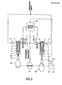
- FIG. 6 shows two pump head sleeves 8.
- the inlet valve unit 27 of one pump head sleeve works together with the outlet valve unit 28 of the other in alternating operation.
- the plungers 21 of the two pump head liners are driven by cams 400 in such a way that, with a certain overlap, one displacement system in each case conveys while the other displacement system sucks.
- the cam profile is designed so that each displacement system performs a pre-compression stroke before the actual delivery stroke. This is done in order to avoid the slump in delivery, which occurs at the beginning of the delivery stroke due to the specific compressibility of the delivery medium due to the increased working pressure and causes a residual pulsation of the delivery flow.
- This principle of compressibility compensation is described in more detail in German patent specification 27 37 062.
- Both cams 400 are driven by a motor 401, which in turn is controlled by a speed controller 405.
- the speed controller 405 is connected to the optical sensor systems 111 scanning the exhaust valve units 28 and also to a piston position sensor 404.
- the piston position sensor 404 scans a sensor wheel 402 seated on the axis of the motor 401 and the cams 400 with two diametrically opposite pins 403.
- the pins are arranged on the transmitter wheel 402 in such a way that they pass the piston position transmitter 404 at the beginning of the pre-compression stroke of the associated displacement system.
- the speed controller 405 receives the message from the optical sensor systems 111 when a displacement system actually starts to convey. Then namely the relevant valve ball of the outlet valve unit 28 lifts off the valve seat and releases the light barrier.
- the speed controller calculates the pre-compression to be applied and modulates the speed of the drive motor for the remaining pre-compression area, which is no longer used for pre-compression. that both pistons provide the selected delivery rate.
- the speed controller 405 derives a correction factor which is superimposed on the engine speed in order to compensate for the additional delivery due to the precompression based on volume at atmospheric pressure. As a result, a constant, pulse-free mass flow is achieved overall.
- the optical sensor system 111 can consist of a light source and a light receiver, which are arranged on opposite sides of the relevant valve unit.
- the system then works on the transmitted light principle.
- an embodiment is also possible which is not based on the interruption of a light beam, but on the change in the refraction conditions in the valve space as a result of the closing and opening of the ball (reflection principle).
Landscapes
- Engineering & Computer Science (AREA)
- Mechanical Engineering (AREA)
- General Engineering & Computer Science (AREA)
- Physics & Mathematics (AREA)
- Fluid Mechanics (AREA)
- General Physics & Mathematics (AREA)
- Reciprocating Pumps (AREA)
- Details Of Reciprocating Pumps (AREA)
Applications Claiming Priority (6)
| Application Number | Priority Date | Filing Date | Title |
|---|---|---|---|
| DE3600341 | 1986-01-08 | ||
| DE3600343 | 1986-01-08 | ||
| DE19863600342 DE3600342A1 (de) | 1986-01-08 | 1986-01-08 | Feindosierpumpe fuer fluessigkeiten, insbesondere zur anwendung in der hplc-technik |
| DE19863600343 DE3600343C2 (de) | 1986-01-08 | 1986-01-08 | Feindosierpumpe für Flüssigkeiten, insbesondere zur Anwendung in der HPLC-Technik |
| DE3600342 | 1986-01-08 | ||
| DE19863600341 DE3600341A1 (de) | 1986-01-08 | 1986-01-08 | Feindosierpumpe fuer fluessigkeiten, insbesondere zur anwendung in der hplc-technik |
Publications (2)
| Publication Number | Publication Date |
|---|---|
| EP0228628A2 true EP0228628A2 (fr) | 1987-07-15 |
| EP0228628A3 EP0228628A3 (fr) | 1989-07-26 |
Family
ID=27193900
Family Applications (1)
| Application Number | Title | Priority Date | Filing Date |
|---|---|---|---|
| EP86117186A Withdrawn EP0228628A3 (fr) | 1986-01-08 | 1986-12-10 | Pompe de dosage de précision pour des liquides, notamment pour l'usage dans la technologie HPLC |
Country Status (1)
| Country | Link |
|---|---|
| EP (1) | EP0228628A3 (fr) |
Cited By (8)
| Publication number | Priority date | Publication date | Assignee | Title |
|---|---|---|---|---|
| EP0270130A3 (fr) * | 1986-12-05 | 1990-02-07 | Saphirwerk Industrieprodukte AG | Pompe de dosage précis pour fluides |
| WO1994010445A1 (fr) * | 1992-10-28 | 1994-05-11 | Herbert Funke | Pompe haute pression pour le dosage precis de liquides |
| WO1997001744A1 (fr) * | 1995-06-29 | 1997-01-16 | Hans Willi Meinz | Procede et dispositif de dosage volumetrique d'un constituant coulant, controle en termes d'usure et de fuites |
| EP1491867A1 (fr) * | 2003-06-27 | 2004-12-29 | CPS Color Equipment S.p.A. | Dispositif et procédé de dosage de quantités préalablement déterminées de liquide contenant de l'air compressible |
| US7721499B2 (en) | 2000-04-20 | 2010-05-25 | Masonite Corporation | Reverse molded panel |
| WO2011101121A1 (fr) * | 2010-02-18 | 2011-08-25 | Grundfos Management A/S | Pompe doseuse |
| CN105043491A (zh) * | 2015-06-10 | 2015-11-11 | 苏州宏恒化工有限公司 | 一种用于硅浆色浆调配的连续计量缸 |
| CN109865316A (zh) * | 2019-04-01 | 2019-06-11 | 上海易创分析仪器有限公司 | 一种全新规格的液相色谱柱 |
Family Cites Families (6)
| Publication number | Priority date | Publication date | Assignee | Title |
|---|---|---|---|---|
| GB191509917A (en) * | 1915-07-07 | 1916-08-17 | William Herford Mort | Improvements in and relating to Pumps. |
| US3934456A (en) * | 1974-07-22 | 1976-01-27 | Varian Associates | Solvent gradient generator for chromatography systems |
| DK143719C (da) * | 1979-01-03 | 1982-03-08 | Radiometer As | Fremgangsmaade til udluftning af en vaeskedoserende stempelpumpe og stempelpumpe med et arrangement til brug ved udoevelse affremgangsmaaden |
| DE3021851C2 (de) * | 1980-06-11 | 1984-04-12 | Pumpenfabrik Urach, 7432 Urach | Hochdruckkolbenpumpe |
| DE3045661C2 (de) * | 1980-12-04 | 1982-11-18 | Schubert & Salzer Maschinenfabrik Ag, 8070 Ingolstadt | Steigrohr-Be- und -Entlüfter |
| DE3122091C1 (de) * | 1981-06-03 | 1982-12-16 | Saphirwerk, Industrieprodukte AG Nidau, 2560 Nidau | Tauchkolbenpumpe |
-
1986
- 1986-12-10 EP EP86117186A patent/EP0228628A3/fr not_active Withdrawn
Cited By (11)
| Publication number | Priority date | Publication date | Assignee | Title |
|---|---|---|---|---|
| EP0270130A3 (fr) * | 1986-12-05 | 1990-02-07 | Saphirwerk Industrieprodukte AG | Pompe de dosage précis pour fluides |
| WO1994010445A1 (fr) * | 1992-10-28 | 1994-05-11 | Herbert Funke | Pompe haute pression pour le dosage precis de liquides |
| US5653876A (en) * | 1992-10-28 | 1997-08-05 | Funke; Herbert | High pressure pump for fine liquid metering |
| WO1997001744A1 (fr) * | 1995-06-29 | 1997-01-16 | Hans Willi Meinz | Procede et dispositif de dosage volumetrique d'un constituant coulant, controle en termes d'usure et de fuites |
| US7721499B2 (en) | 2000-04-20 | 2010-05-25 | Masonite Corporation | Reverse molded panel |
| EP1491867A1 (fr) * | 2003-06-27 | 2004-12-29 | CPS Color Equipment S.p.A. | Dispositif et procédé de dosage de quantités préalablement déterminées de liquide contenant de l'air compressible |
| WO2011101121A1 (fr) * | 2010-02-18 | 2011-08-25 | Grundfos Management A/S | Pompe doseuse |
| EP2362101A1 (fr) | 2010-02-18 | 2011-08-31 | Grundfos Management A/S | Pompe de dosage |
| CN105043491A (zh) * | 2015-06-10 | 2015-11-11 | 苏州宏恒化工有限公司 | 一种用于硅浆色浆调配的连续计量缸 |
| CN105043491B (zh) * | 2015-06-10 | 2018-05-15 | 苏州宏恒化工有限公司 | 一种用于硅浆色浆调配的连续计量缸 |
| CN109865316A (zh) * | 2019-04-01 | 2019-06-11 | 上海易创分析仪器有限公司 | 一种全新规格的液相色谱柱 |
Also Published As
| Publication number | Publication date |
|---|---|
| EP0228628A3 (fr) | 1989-07-26 |
Similar Documents
| Publication | Publication Date | Title |
|---|---|---|
| DE3122091C1 (de) | Tauchkolbenpumpe | |
| DE69621828T2 (de) | HOCHDRUCKSPRITZENPUMPE für Mikro-Volumina | |
| EP2906815B1 (fr) | Soupape pour une pompe | |
| WO2009092345A1 (fr) | Dispositif de distribution d’échantillon pour chromatographie en phase liquide, en particulier pour chromatographie en phase liquide à haute performance | |
| EP1101931A2 (fr) | Système d'injection à haute pression avec common rail | |
| EP0682749B1 (fr) | Pompe haute pression pour le dosage precis de liquides | |
| EP0061415A1 (fr) | Soupape pour systèmes hydrauliques | |
| DE3812627C2 (fr) | ||
| EP0228628A2 (fr) | Pompe de dosage de précision pour des liquides, notamment pour l'usage dans la technologie HPLC | |
| DE2506928C3 (de) | Gebirgsschlagventil für hydraulische Grubenstempel | |
| EP0464165B1 (fr) | Pompe a plongeur a pression maximale | |
| DE3600341A1 (de) | Feindosierpumpe fuer fluessigkeiten, insbesondere zur anwendung in der hplc-technik | |
| DE69915946T2 (de) | Dichtung | |
| WO1993019301A1 (fr) | Dispositif hydraulique d'entrainement a verin | |
| DE3600343C2 (de) | Feindosierpumpe für Flüssigkeiten, insbesondere zur Anwendung in der HPLC-Technik | |
| DE69832505T2 (de) | Kupplung für eine hochdruckpumpe | |
| DE3407315A1 (de) | Dehnspannwerkzeug mit kontrolleinrichtung | |
| DE19725564C2 (de) | Radialkolbenpumpe | |
| DE19854719B4 (de) | Kolbenpumpe | |
| DE3689898T2 (de) | Verbindungssystem. | |
| DE102010000276A1 (de) | Kraftstoffzuführvorrichtung | |
| DE3641652C2 (de) | Feindosierpumpe für Flüssigkeiten | |
| DE3600342A1 (de) | Feindosierpumpe fuer fluessigkeiten, insbesondere zur anwendung in der hplc-technik | |
| EP0017789B1 (fr) | Arrangement piston et cylindre | |
| DE2824184C2 (fr) |
Legal Events
| Date | Code | Title | Description |
|---|---|---|---|
| PUAI | Public reference made under article 153(3) epc to a published international application that has entered the european phase |
Free format text: ORIGINAL CODE: 0009012 |
|
| AK | Designated contracting states |
Kind code of ref document: A2 Designated state(s): AT BE CH DE FR GB IT LI NL SE |
|
| PUAL | Search report despatched |
Free format text: ORIGINAL CODE: 0009013 |
|
| AK | Designated contracting states |
Kind code of ref document: A3 Designated state(s): AT BE CH DE FR GB IT LI NL SE |
|
| 17P | Request for examination filed |
Effective date: 19891127 |
|
| 17Q | First examination report despatched |
Effective date: 19900829 |
|
| STAA | Information on the status of an ep patent application or granted ep patent |
Free format text: STATUS: THE APPLICATION IS DEEMED TO BE WITHDRAWN |
|
| 18D | Application deemed to be withdrawn |
Effective date: 19911022 |
|
| RIN1 | Information on inventor provided before grant (corrected) |
Inventor name: FUNKE, HERBERT, DR. |