EP1491867A1 - Dispositif et procédé de dosage de quantités préalablement déterminées de liquide contenant de l'air compressible - Google Patents
Dispositif et procédé de dosage de quantités préalablement déterminées de liquide contenant de l'air compressible Download PDFInfo
- Publication number
- EP1491867A1 EP1491867A1 EP20030425426 EP03425426A EP1491867A1 EP 1491867 A1 EP1491867 A1 EP 1491867A1 EP 20030425426 EP20030425426 EP 20030425426 EP 03425426 A EP03425426 A EP 03425426A EP 1491867 A1 EP1491867 A1 EP 1491867A1
- Authority
- EP
- European Patent Office
- Prior art keywords
- dispensing
- shutter
- fluid product
- valve
- opening
- Prior art date
- Legal status (The legal status is an assumption and is not a legal conclusion. Google has not performed a legal analysis and makes no representation as to the accuracy of the status listed.)
- Granted
Links
Images


Classifications
-
- G—PHYSICS
- G01—MEASURING; TESTING
- G01F—MEASURING VOLUME, VOLUME FLOW, MASS FLOW OR LIQUID LEVEL; METERING BY VOLUME
- G01F11/00—Apparatus requiring external operation adapted at each repeated and identical operation to measure and separate a predetermined volume of fluid or fluent solid material from a supply or container, without regard to weight, and to deliver it
- G01F11/02—Apparatus requiring external operation adapted at each repeated and identical operation to measure and separate a predetermined volume of fluid or fluent solid material from a supply or container, without regard to weight, and to deliver it with measuring chambers which expand or contract during measurement
- G01F11/021—Apparatus requiring external operation adapted at each repeated and identical operation to measure and separate a predetermined volume of fluid or fluent solid material from a supply or container, without regard to weight, and to deliver it with measuring chambers which expand or contract during measurement of the piston type
- G01F11/029—Apparatus requiring external operation adapted at each repeated and identical operation to measure and separate a predetermined volume of fluid or fluent solid material from a supply or container, without regard to weight, and to deliver it with measuring chambers which expand or contract during measurement of the piston type provided with electric controlling means
-
- F—MECHANICAL ENGINEERING; LIGHTING; HEATING; WEAPONS; BLASTING
- F04—POSITIVE - DISPLACEMENT MACHINES FOR LIQUIDS; PUMPS FOR LIQUIDS OR ELASTIC FLUIDS
- F04B—POSITIVE-DISPLACEMENT MACHINES FOR LIQUIDS; PUMPS
- F04B13/00—Pumps specially modified to deliver fixed or variable measured quantities
Definitions
- the invention has been developed with particular regard to a circuit for dispensing fluid products, in particular colouring agents, paints and the like, which circuit comprises means for delivering at least one fluid product, which means can be activated selectively to send the at least one fluid product to at least one dispensing duct, valve means which are disposed on the at least one dispensing duct and which can be opened to dispense the at least one fluid product, and control means for bringing about the activation of the delivery means and dispensing a predetermined quantity of the at least one fluid product.
- the invention relates also to a method for dispensing fluid products, in particular colouring agents, paints and the like, which method comprises the stage of providing a dispensing circuit comprising means for delivering at least one fluid product, which means can be activated selectively to send the at least one fluid product to at least one dispensing duct, and valve means which are disposed on the at least one dispensing duct and which can be opened to dispense the at least one fluid product, and the stage of activating the delivery means to send the at least one fluid product to the dispensing duct.
- a dispensing circuit of the type indicated above is known from US-6457607 which describes a pumping unit comprising a stepper motor which operates a bellows pumping chamber for sending a fluid product to a dispensing duct along which a non-return valve is positioned.
- the stepper motor is operated for a determined number of steps which bring about a corresponding reduction in volume of the pumping chamber and therefore the delivery of a specific volume of fluid product.
- the volume of fluid product delivered by the dispensing circuit may not correspond to the actual volume of fluid product desired.
- the fluid product to be delivered which is substantially incompressible per se , may incorporate a quantity of highly compressible air.
- the reduction in the volume of the pumping chamber caused by the operation of the motor is in part wasted in compressing the air inside the bellows and the dispensing duct, without a corresponding effective delivery of the fluid product. Consequently, the volume of fluid product actually delivered by the above-mentioned dispensing circuit may be smaller than that expected and desired on the basis of the operation of the motor.
- the traditional solution to the problem indicated above is to calibrate the dispensing circuit in such a manner as to determine correcting values for the activation period or activation stroke of the motor, which are such as to compensate for the effect caused by the presence of air in the circuit and inside the incompressible fluid product to be delivered.
- the quantity of air incorporated inside the incompressible fluid to be delivered is not constant over time and may vary within rather wide limits, to such an extent as to influence the precision and repeatability performance in the delivery operations of the above-mentioned known circuit.
- the applicant has found that often the quantity of air incorporated inside the colouring agent is at a maximum immediately after the reservoir of fluid product has been filled or topped up and tends to decrease with the passage of time. Unless the delivery circuit is calibrated continuously and repeatedly, it is extremely difficult, if not impossible, to obtain good precision and repeatability of delivery over time of the delivery circuit of the prior art.
- Another solution adopted in circuits of a more traditional design for dispensing colouring agents, consists in providing a controlled delivery valve, that is to say, a valve disposed on the dispensing duct, preferably disposed in the vicinity of the delivery nozzle for the fluid product, which opens on command for the time necessary to deliver the desired quantity thereof.
- the controlled or actuated valves of the above-mentioned type are expensive, require constant maintenance and normally have to provide a bypass with the possibility of recirculating the fluid product to the reservoir when the valve is in the closed position, with a consequent complication of the dispensing circuit and the control thereof, it should be noted that the actual quantity of fluid product delivered is a function both of the opening time of the actuated valve and of the flow of fluid in the delivery duct.
- the object of the present invention is to overcome the problems of the prior art and to provide a circuit and a method for dispensing fluid products in which the quantity, and in particular the volume, of fluid products actually dispensed coincides substantially with the nominal quantity desired and required by the user.
- Another object of the present invention is to provide a circuit and a method for carrying out a dispensing operation with a high degree of repeatability, that is to say, in which the above-mentioned correspondence between the quantity of fluid products actually delivered and the desired nominal quantity is constant over time without the necessity for frequent calibrations of the circuit.
- a further object of the present invention is to provide a dispensing circuit and method which are simple and economical, safe, reliable, easy to use and which do not provide for complex or expensive maintenance operations.
- the invention relates to a dispensing circuit of the type indicated in the preamble of the present description, comprising sensor means for detecting the opening of the valve means and thus signalling to the control means the effective start of the dispensing operation.
- the invention relates also to a dispensing method of the type indicated in the preamble of the present description, comprising the stages of signalling the opening of the valve means and actuating the dispensing of the at least one fluid product from the signalling of the opening of the valve means.
- the sensor means are in communication with the control means, for example, by way of a wired connection, such as an electrical conductor, an optical fibre or the like, or with a system without wires, for example via radio, an infrared ray system or other similar means, in order to transmit to the control means a signal indicating the opening and/or the closing of the valve means.
- a wired connection such as an electrical conductor, an optical fibre or the like
- a system without wires for example via radio, an infrared ray system or other similar means
- control system can use as a reference for the dispensing of the desired quantity of fluid product the effective start of the dispensing operation, of which it is informed by means of the signals gathered by the sensor means, and which thus coincides with the opening of the valve means, irrespective of when the delivery means were activated, in particular the control motor of the pumping unit.
- valve means The opening of the valve means and the consequent signal indicating the start of the dispensing operation are independent of any other control means and result purely from the attainment of conditions fixed beforehand, for example the pressure differential in the dispensing duct upstream and downstream, respectively, of the valve means. This makes it possible to use a simple non-controlled non-return valve as the valve means.
- the fact that the determination and signalling of the effective start of the delivery of fluid product take place independently of the control system used enables the present invention to be adopted also in circuits provided with controlled valves, because the lack of a signal confirming that the valve has opened as a consequence of a controlled opening actuation thereof can warn of a possible obstruction or leakage in the dispensing duct which prevents the attainment of the pre-set delivery conditions in the vicinity of the valve.
- This information can be used in various manners, for example, to activate an error sequence or to interrupt the operation of the circuit.
- the shutter of the valve means may advantageously incorporate or itself be the means of signalling its own position or its own opening and/or closing movement. It is particularly advantageous to incorporate in the shutter or to produce the entire shutter with a material which interacts with a sensor placed outside the valve body in order to generate a variable electromagnetic field and a consequent electrical signal indicating the position and/or the movement of the shutter. For that purpose it is possible to use the typical characteristics of Hall-effect sensors, or of magnetostrictive materials or the like, which can all be adapted to implement the present invention.
- the delivery means comprise an electrical motor which is preferably, although this is not to constitute a limitation, a stepper motor, for example, for moving the movable wall of a variable-volume pumping chamber by means of a linear actuator of the type having an internally and externally threaded member.
- the control system causes the stepper motor to move by the number of steps necessary to dispense the predetermined quantity, starting to count them from the reference instant coinciding with the moment at which the valve means are opened.
- the valve means are along the dispensing duct, preferably, although this is not to constitute a limitation, in the vicinity of or at the location of a delivery nozzle.
- a high degree of dispensing precision and repeatability is thus achieved because the transient state during which the air in the delivery circuit is compressed without fluid product being dispensed also takes into account the quantity of fluid product contained in the delivery duct, downstream of the pumping means but upstream of the valve means. If the structural details of the machine for dispensing fluid products include long delivery ducts, the difference in performance compared with known machines may be substantial.
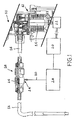
- the shutter 26 is movable from the closing position, in which it abuts the cutting rim 44, to an opening position in which it is moved back relative to the internal mouth 40 inside the outlet portion of the cavity 36.
- the thrust necessary to keep the shutter in the position closing the valve 18 is provided, for example, by resilient means, such as a helical spring 46 coupled at one end 48 thereof to the back 50 of the shutter 26 and at the opposite end 49 to a shoulder 52 facing the internal mouth 40 and formed in the outlet portion 38b.
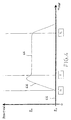
- control system 28 can cause the stepper motor 20 to advance by a number of steps corresponding to the desired quantity of product from instant T 1 at which it receives from the sensor 24 the signal corresponding to the movement of the fluid product or to the position of maximum opening Pm of the shutter 26.
- the quantity of product dispensed is determined by the control system by causing the motor means to move by the necessary amount at the end of an initial transient state in which the movement of the motor means does not correspond to a dispensing of the fluid products but only to a compression which brings the fluid products to the pressure necessary to overcome the resistance to movement in the circuit.
- the quantity of product dispensed corresponds to that theoretically required because the transient state of compression is not regarded as an actual dispensing period.
- a further advantage of the present invention is that the circuit does not have to be calibrated each time there is a change in the compressibility of the fluid product in question, for example, for the different quantity of air in suspension in the same fluid product before and after a period of decanting into a reservoir supplying the circuit, given that the end of the transient state of compression and the start of the dispensing operation always coincide with the opening of the non-return valve 18.
- Another advantage of the present invention is that it includes a control system having very simple feedback, given that there is no need to control the valves but only to signal their opening as a reference for starting to count the quantity of product to be dispensed, which is effectively delivered by controlling only the motor means on the basis of that reference.
- the dispensing circuit of the present invention is very economical.
Landscapes
- Engineering & Computer Science (AREA)
- Physics & Mathematics (AREA)
- Fluid Mechanics (AREA)
- General Physics & Mathematics (AREA)
- Mechanical Engineering (AREA)
- General Engineering & Computer Science (AREA)
- Loading And Unloading Of Fuel Tanks Or Ships (AREA)
- Feeding, Discharge, Calcimining, Fusing, And Gas-Generation Devices (AREA)
- Devices For Dispensing Beverages (AREA)
- Beverage Vending Machines With Cups, And Gas Or Electricity Vending Machines (AREA)
- Jet Pumps And Other Pumps (AREA)
Priority Applications (4)
| Application Number | Priority Date | Filing Date | Title |
|---|---|---|---|
| DE60307446T DE60307446T2 (de) | 2003-06-27 | 2003-06-27 | Vorrichtung und Verfahren zum Dosieren einer vorbestimmten Menge kompressible Luft enthaltenden Flüssigkeit |
| ES03425426T ES2269966T3 (es) | 2003-06-27 | 2003-06-27 | Dispositivo y metodo para dosificar una cantidad predeterminada de liquido que incorpora aire comprimible. |
| AT03425426T ATE335989T1 (de) | 2003-06-27 | 2003-06-27 | Vorrichtung und verfahren zum dosieren einer vorbestimmten menge kompressible luft enthaltenden flüssigkeit |
| EP03425426A EP1491867B1 (fr) | 2003-06-27 | 2003-06-27 | Dispositif et procédé de dosage de quantités préalablement déterminées de liquide contenant de l'air compressible |
Applications Claiming Priority (1)
| Application Number | Priority Date | Filing Date | Title |
|---|---|---|---|
| EP03425426A EP1491867B1 (fr) | 2003-06-27 | 2003-06-27 | Dispositif et procédé de dosage de quantités préalablement déterminées de liquide contenant de l'air compressible |
Publications (2)
| Publication Number | Publication Date |
|---|---|
| EP1491867A1 true EP1491867A1 (fr) | 2004-12-29 |
| EP1491867B1 EP1491867B1 (fr) | 2006-08-09 |
Family
ID=33396141
Family Applications (1)
| Application Number | Title | Priority Date | Filing Date |
|---|---|---|---|
| EP03425426A Expired - Lifetime EP1491867B1 (fr) | 2003-06-27 | 2003-06-27 | Dispositif et procédé de dosage de quantités préalablement déterminées de liquide contenant de l'air compressible |
Country Status (4)
| Country | Link |
|---|---|
| EP (1) | EP1491867B1 (fr) |
| AT (1) | ATE335989T1 (fr) |
| DE (1) | DE60307446T2 (fr) |
| ES (1) | ES2269966T3 (fr) |
Cited By (1)
| Publication number | Priority date | Publication date | Assignee | Title |
|---|---|---|---|---|
| DE202019000970U1 (de) | 2019-02-25 | 2019-04-11 | Eberhard Zipplies | Strömungswächter |
Families Citing this family (2)
| Publication number | Priority date | Publication date | Assignee | Title |
|---|---|---|---|---|
| DE102012010055A1 (de) * | 2012-03-20 | 2013-09-26 | HyPneu Service GmbH | Einrichtung und Verfahren zur Überwachung der Dichtigkeit von druckluftverbrauchenden oder druckluftführenden pneumatischen Elementen |
| DE102019001406B4 (de) * | 2019-02-25 | 2022-05-25 | Eberhard Zipplies | Strömungswächter |
Citations (3)
| Publication number | Priority date | Publication date | Assignee | Title |
|---|---|---|---|---|
| EP0228628A2 (fr) * | 1986-01-08 | 1987-07-15 | Saphirwerk Industrieprodukte AG | Pompe de dosage de précision pour des liquides, notamment pour l'usage dans la technologie HPLC |
| WO1991008445A1 (fr) * | 1989-11-27 | 1991-06-13 | Framo Developments (Uk) Limited | Appareil de debitmetre |
| WO1993018301A1 (fr) * | 1992-03-02 | 1993-09-16 | Putzmeister-Werk Maschinenfabrik Gmbh | Methode de mesure du debit de pompes a liquides epais |
-
2003
- 2003-06-27 DE DE60307446T patent/DE60307446T2/de not_active Expired - Lifetime
- 2003-06-27 ES ES03425426T patent/ES2269966T3/es not_active Expired - Lifetime
- 2003-06-27 EP EP03425426A patent/EP1491867B1/fr not_active Expired - Lifetime
- 2003-06-27 AT AT03425426T patent/ATE335989T1/de not_active IP Right Cessation
Patent Citations (3)
| Publication number | Priority date | Publication date | Assignee | Title |
|---|---|---|---|---|
| EP0228628A2 (fr) * | 1986-01-08 | 1987-07-15 | Saphirwerk Industrieprodukte AG | Pompe de dosage de précision pour des liquides, notamment pour l'usage dans la technologie HPLC |
| WO1991008445A1 (fr) * | 1989-11-27 | 1991-06-13 | Framo Developments (Uk) Limited | Appareil de debitmetre |
| WO1993018301A1 (fr) * | 1992-03-02 | 1993-09-16 | Putzmeister-Werk Maschinenfabrik Gmbh | Methode de mesure du debit de pompes a liquides epais |
Cited By (1)
| Publication number | Priority date | Publication date | Assignee | Title |
|---|---|---|---|---|
| DE202019000970U1 (de) | 2019-02-25 | 2019-04-11 | Eberhard Zipplies | Strömungswächter |
Also Published As
| Publication number | Publication date |
|---|---|
| DE60307446T2 (de) | 2007-03-08 |
| DE60307446D1 (de) | 2006-09-21 |
| ATE335989T1 (de) | 2006-09-15 |
| EP1491867B1 (fr) | 2006-08-09 |
| ES2269966T3 (es) | 2007-04-01 |
Similar Documents
| Publication | Publication Date | Title |
|---|---|---|
| EP0607308B1 (fr) | Appareil de regulation de l'extension du diaphragme dans une pompe de dosage a diaphragme | |
| US8608025B2 (en) | Pneumatic liquid dispensing apparatus and method | |
| JPS5952071B2 (ja) | 液噴射式記録装置 | |
| US20020112759A1 (en) | Apparatus for dosing lubricant into an air line | |
| US20220228897A1 (en) | Dosing unit and method for dosing a liquid | |
| JPH03182913A (ja) | 不圧縮性流体の物理的状態を監視し制御するための方法及び装置 | |
| EP1910678B1 (fr) | Pompe alternative munie d'un robinet d'air surveille electroniquement et d'une surveillance electronique de la batterie et du solenoide | |
| CA2556059A1 (fr) | Methode et dispositif de remplissage d'un recipient avec une quantite predeterminee de fluide, et remplisseuse | |
| JPH09117709A (ja) | 流体材料吐出方法 | |
| US6053285A (en) | Apparatus for dispensing measured quantities of lubricant | |
| US4784584A (en) | Metering device | |
| US7367473B2 (en) | Circuit for dispensing fluid products, in particular colouring agents, paints or similar fluid products | |
| EP1491867B1 (fr) | Dispositif et procédé de dosage de quantités préalablement déterminées de liquide contenant de l'air compressible | |
| WO2015031884A1 (fr) | Pompe de portion à haute viscosité | |
| CN106999966A (zh) | 具有改善的压力控制的液体分配系统 | |
| US3785526A (en) | Dispensing apparatus | |
| CN1823264A (zh) | 计量装置 | |
| WO2018162883A1 (fr) | Appareil de distribution d'un produit fluide | |
| AU600722B2 (en) | System for dispensing precisely metered quantities of a fluid and method of utilizing the same | |
| US4616978A (en) | Fluid supply surge control system | |
| EP1841684B1 (fr) | Gestion de produits fluides | |
| CN115315578B (zh) | 可变排量液压泵 | |
| EP0745832B1 (fr) | Dispositif pour la distribution volumique de fluides | |
| CN100540454C (zh) | 用于分配的膜和电磁控制阀 | |
| GB2200616A (en) | Liquid metering device |
Legal Events
| Date | Code | Title | Description |
|---|---|---|---|
| PUAI | Public reference made under article 153(3) epc to a published international application that has entered the european phase |
Free format text: ORIGINAL CODE: 0009012 |
|
| AK | Designated contracting states |
Kind code of ref document: A1 Designated state(s): AT BE BG CH CY CZ DE DK EE ES FI FR GB GR HU IE IT LI LU MC NL PT RO SE SI SK TR |
|
| AX | Request for extension of the european patent |
Extension state: AL LT LV MK |
|
| 17P | Request for examination filed |
Effective date: 20050623 |
|
| AKX | Designation fees paid |
Designated state(s): AT BE BG CH CY CZ DE DK EE ES FI FR GB GR HU IE IT LI LU MC NL PT RO SE SI SK TR |
|
| GRAP | Despatch of communication of intention to grant a patent |
Free format text: ORIGINAL CODE: EPIDOSNIGR1 |
|
| GRAS | Grant fee paid |
Free format text: ORIGINAL CODE: EPIDOSNIGR3 |
|
| RAP1 | Party data changed (applicant data changed or rights of an application transferred) |
Owner name: CPS COLOR EQUIPMENT S.P.A. CON UNICO SOCIO |
|
| GRAA | (expected) grant |
Free format text: ORIGINAL CODE: 0009210 |
|
| AK | Designated contracting states |
Kind code of ref document: B1 Designated state(s): AT BE BG CH CY CZ DE DK EE ES FI FR GB GR HU IE IT LI LU MC NL PT RO SE SI SK TR |
|
| PG25 | Lapsed in a contracting state [announced via postgrant information from national office to epo] |
Ref country code: IT Free format text: LAPSE BECAUSE OF FAILURE TO SUBMIT A TRANSLATION OF THE DESCRIPTION OR TO PAY THE FEE WITHIN THE PRESCRIBED TIME-LIMIT;WARNING: LAPSES OF ITALIAN PATENTS WITH EFFECTIVE DATE BEFORE 2007 MAY HAVE OCCURRED AT ANY TIME BEFORE 2007. THE CORRECT EFFECTIVE DATE MAY BE DIFFERENT FROM THE ONE RECORDED. Effective date: 20060809 Ref country code: CZ Free format text: LAPSE BECAUSE OF FAILURE TO SUBMIT A TRANSLATION OF THE DESCRIPTION OR TO PAY THE FEE WITHIN THE PRESCRIBED TIME-LIMIT Effective date: 20060809 Ref country code: AT Free format text: LAPSE BECAUSE OF FAILURE TO SUBMIT A TRANSLATION OF THE DESCRIPTION OR TO PAY THE FEE WITHIN THE PRESCRIBED TIME-LIMIT Effective date: 20060809 Ref country code: SI Free format text: LAPSE BECAUSE OF FAILURE TO SUBMIT A TRANSLATION OF THE DESCRIPTION OR TO PAY THE FEE WITHIN THE PRESCRIBED TIME-LIMIT Effective date: 20060809 Ref country code: LI Free format text: LAPSE BECAUSE OF FAILURE TO SUBMIT A TRANSLATION OF THE DESCRIPTION OR TO PAY THE FEE WITHIN THE PRESCRIBED TIME-LIMIT Effective date: 20060809 Ref country code: CH Free format text: LAPSE BECAUSE OF FAILURE TO SUBMIT A TRANSLATION OF THE DESCRIPTION OR TO PAY THE FEE WITHIN THE PRESCRIBED TIME-LIMIT Effective date: 20060809 Ref country code: BE Free format text: LAPSE BECAUSE OF FAILURE TO SUBMIT A TRANSLATION OF THE DESCRIPTION OR TO PAY THE FEE WITHIN THE PRESCRIBED TIME-LIMIT Effective date: 20060809 Ref country code: SK Free format text: LAPSE BECAUSE OF FAILURE TO SUBMIT A TRANSLATION OF THE DESCRIPTION OR TO PAY THE FEE WITHIN THE PRESCRIBED TIME-LIMIT Effective date: 20060809 Ref country code: RO Free format text: LAPSE BECAUSE OF FAILURE TO SUBMIT A TRANSLATION OF THE DESCRIPTION OR TO PAY THE FEE WITHIN THE PRESCRIBED TIME-LIMIT Effective date: 20060809 |
|
| REG | Reference to a national code |
Ref country code: GB Ref legal event code: FG4D |
|
| REG | Reference to a national code |
Ref country code: CH Ref legal event code: EP |
|
| REG | Reference to a national code |
Ref country code: IE Ref legal event code: FG4D |
|
| REF | Corresponds to: |
Ref document number: 60307446 Country of ref document: DE Date of ref document: 20060921 Kind code of ref document: P |
|
| PG25 | Lapsed in a contracting state [announced via postgrant information from national office to epo] |
Ref country code: DK Free format text: LAPSE BECAUSE OF FAILURE TO SUBMIT A TRANSLATION OF THE DESCRIPTION OR TO PAY THE FEE WITHIN THE PRESCRIBED TIME-LIMIT Effective date: 20061109 Ref country code: BG Free format text: LAPSE BECAUSE OF FAILURE TO SUBMIT A TRANSLATION OF THE DESCRIPTION OR TO PAY THE FEE WITHIN THE PRESCRIBED TIME-LIMIT Effective date: 20061109 Ref country code: SE Free format text: LAPSE BECAUSE OF FAILURE TO SUBMIT A TRANSLATION OF THE DESCRIPTION OR TO PAY THE FEE WITHIN THE PRESCRIBED TIME-LIMIT Effective date: 20061109 |
|
| REG | Reference to a national code |
Ref country code: GR Ref legal event code: EP Ref document number: 20060403832 Country of ref document: GR |
|
| PG25 | Lapsed in a contracting state [announced via postgrant information from national office to epo] |
Ref country code: PT Free format text: LAPSE BECAUSE OF FAILURE TO SUBMIT A TRANSLATION OF THE DESCRIPTION OR TO PAY THE FEE WITHIN THE PRESCRIBED TIME-LIMIT Effective date: 20070109 |
|
| REG | Reference to a national code |
Ref country code: CH Ref legal event code: PL |
|
| ET3 | Fr: translation filed ** decision concerning opposition | ||
| REG | Reference to a national code |
Ref country code: ES Ref legal event code: FG2A Ref document number: 2269966 Country of ref document: ES Kind code of ref document: T3 |
|
| PLBE | No opposition filed within time limit |
Free format text: ORIGINAL CODE: 0009261 |
|
| STAA | Information on the status of an ep patent application or granted ep patent |
Free format text: STATUS: NO OPPOSITION FILED WITHIN TIME LIMIT |
|
| 26N | No opposition filed |
Effective date: 20070510 |
|
| PG25 | Lapsed in a contracting state [announced via postgrant information from national office to epo] |
Ref country code: MC Free format text: LAPSE BECAUSE OF NON-PAYMENT OF DUE FEES Effective date: 20070630 |
|
| PG25 | Lapsed in a contracting state [announced via postgrant information from national office to epo] |
Ref country code: IE Free format text: LAPSE BECAUSE OF NON-PAYMENT OF DUE FEES Effective date: 20070627 |
|
| PG25 | Lapsed in a contracting state [announced via postgrant information from national office to epo] |
Ref country code: EE Free format text: LAPSE BECAUSE OF FAILURE TO SUBMIT A TRANSLATION OF THE DESCRIPTION OR TO PAY THE FEE WITHIN THE PRESCRIBED TIME-LIMIT Effective date: 20060809 |
|
| PG25 | Lapsed in a contracting state [announced via postgrant information from national office to epo] |
Ref country code: CY Free format text: LAPSE BECAUSE OF FAILURE TO SUBMIT A TRANSLATION OF THE DESCRIPTION OR TO PAY THE FEE WITHIN THE PRESCRIBED TIME-LIMIT Effective date: 20060809 Ref country code: LU Free format text: LAPSE BECAUSE OF NON-PAYMENT OF DUE FEES Effective date: 20070627 |
|
| PG25 | Lapsed in a contracting state [announced via postgrant information from national office to epo] |
Ref country code: HU Free format text: LAPSE BECAUSE OF FAILURE TO SUBMIT A TRANSLATION OF THE DESCRIPTION OR TO PAY THE FEE WITHIN THE PRESCRIBED TIME-LIMIT Effective date: 20070210 Ref country code: TR Free format text: LAPSE BECAUSE OF FAILURE TO SUBMIT A TRANSLATION OF THE DESCRIPTION OR TO PAY THE FEE WITHIN THE PRESCRIBED TIME-LIMIT Effective date: 20060809 |
|
| PGFP | Annual fee paid to national office [announced via postgrant information from national office to epo] |
Ref country code: NL Payment date: 20120626 Year of fee payment: 10 Ref country code: DE Payment date: 20120622 Year of fee payment: 10 |
|
| PGFP | Annual fee paid to national office [announced via postgrant information from national office to epo] |
Ref country code: GR Payment date: 20120627 Year of fee payment: 10 Ref country code: FR Payment date: 20120705 Year of fee payment: 10 Ref country code: FI Payment date: 20120625 Year of fee payment: 10 Ref country code: GB Payment date: 20120629 Year of fee payment: 10 |
|
| PGFP | Annual fee paid to national office [announced via postgrant information from national office to epo] |
Ref country code: IT Payment date: 20120627 Year of fee payment: 10 |
|
| PGFP | Annual fee paid to national office [announced via postgrant information from national office to epo] |
Ref country code: ES Payment date: 20120627 Year of fee payment: 10 |
|
| REG | Reference to a national code |
Ref country code: NL Ref legal event code: V1 Effective date: 20140101 |
|
| GBPC | Gb: european patent ceased through non-payment of renewal fee |
Effective date: 20130627 |
|
| REG | Reference to a national code |
Ref country code: GR Ref legal event code: ML Ref document number: 20060403832 Country of ref document: GR Effective date: 20140103 |
|
| PG25 | Lapsed in a contracting state [announced via postgrant information from national office to epo] |
Ref country code: FI Free format text: LAPSE BECAUSE OF NON-PAYMENT OF DUE FEES Effective date: 20130627 |
|
| REG | Reference to a national code |
Ref country code: FR Ref legal event code: ST Effective date: 20140228 |
|
| REG | Reference to a national code |
Ref country code: DE Ref legal event code: R119 Ref document number: 60307446 Country of ref document: DE Effective date: 20140101 |
|
| PG25 | Lapsed in a contracting state [announced via postgrant information from national office to epo] |
Ref country code: GB Free format text: LAPSE BECAUSE OF NON-PAYMENT OF DUE FEES Effective date: 20130627 Ref country code: NL Free format text: LAPSE BECAUSE OF NON-PAYMENT OF DUE FEES Effective date: 20140101 Ref country code: DE Free format text: LAPSE BECAUSE OF NON-PAYMENT OF DUE FEES Effective date: 20140101 |
|
| PG25 | Lapsed in a contracting state [announced via postgrant information from national office to epo] |
Ref country code: IT Free format text: LAPSE BECAUSE OF NON-PAYMENT OF DUE FEES Effective date: 20130627 Ref country code: GR Free format text: LAPSE BECAUSE OF NON-PAYMENT OF DUE FEES Effective date: 20140103 Ref country code: FR Free format text: LAPSE BECAUSE OF NON-PAYMENT OF DUE FEES Effective date: 20130701 |
|
| REG | Reference to a national code |
Ref country code: ES Ref legal event code: FD2A Effective date: 20140707 |
|
| PG25 | Lapsed in a contracting state [announced via postgrant information from national office to epo] |
Ref country code: ES Free format text: LAPSE BECAUSE OF NON-PAYMENT OF DUE FEES Effective date: 20130628 |