EP0228642A2 - Codeur à masque flottant - Google Patents
Codeur à masque flottant Download PDFInfo
- Publication number
- EP0228642A2 EP0228642A2 EP86117456A EP86117456A EP0228642A2 EP 0228642 A2 EP0228642 A2 EP 0228642A2 EP 86117456 A EP86117456 A EP 86117456A EP 86117456 A EP86117456 A EP 86117456A EP 0228642 A2 EP0228642 A2 EP 0228642A2
- Authority
- EP
- European Patent Office
- Prior art keywords
- disk
- circuit board
- mask
- assembly
- shaft
- Prior art date
- Legal status (The legal status is an assumption and is not a legal conclusion. Google has not performed a legal analysis and makes no representation as to the accuracy of the status listed.)
- Withdrawn
Links
- 125000006850 spacer group Chemical group 0.000 claims abstract description 15
- 238000004519 manufacturing process Methods 0.000 claims description 11
- 238000000034 method Methods 0.000 claims description 6
- 239000000758 substrate Substances 0.000 claims description 6
- 238000005476 soldering Methods 0.000 claims description 2
- 230000003993 interaction Effects 0.000 claims 1
- 230000003287 optical effect Effects 0.000 abstract description 22
- 238000003754 machining Methods 0.000 description 9
- 239000000853 adhesive Substances 0.000 description 2
- 230000001070 adhesive effect Effects 0.000 description 2
- 238000009434 installation Methods 0.000 description 2
- 239000000654 additive Substances 0.000 description 1
- 230000000996 additive effect Effects 0.000 description 1
- 238000010420 art technique Methods 0.000 description 1
- 238000005266 casting Methods 0.000 description 1
- 238000013100 final test Methods 0.000 description 1
- 230000007774 longterm Effects 0.000 description 1
- 230000002093 peripheral effect Effects 0.000 description 1
Images


Classifications
-
- H—ELECTRICITY
- H03—ELECTRONIC CIRCUITRY
- H03M—CODING; DECODING; CODE CONVERSION IN GENERAL
- H03M1/00—Analogue/digital conversion; Digital/analogue conversion
- H03M1/10—Calibration or testing
- H03M1/1066—Mechanical or optical alignment
Definitions
- the invention relates generally to optical shaft encoders and, more specifically, to a method of manufacturing an optical shaft encoder with a minimum of precision machining.
- Optical shaft encoders typically include a rotating code disk coupled to a shaft and convert the rotary position to a digital output signal.
- the code disk includes predetermined opaque and transparent patterns or lines disposed about the circumference.
- the code disk rotates between a light source and a photodetector.
- a mask is disposed between the code disk and the photodetector such that, as the code disk rotates, light from the light source is alternately blocked and transmitted through the code disk and mask. The light which is transmitted through the code disk and mask strikes the photodetector which generates electrical output signals indicative of the position of the rotating code disk and the shaft to which it is coupled.
- US patent 4 345 149 discloses an optical shaft encoder having a mounting support which carries the light source.
- the optical encoder assembly is centered on a motor casing with respect to the motor shaft by a disc-shaped centering fixture.
- the fixture has a central bore of a diameter corresponding to the diameter of the motor shaft, and an annular peripheral downwardly depending lip at a precise radial distance corresponding to the radial distance between the geometrical center of the mounting support and its circular periphery.
- the disc-shaped fixture can overlie the mounting support with its lip engaged about the periphery with its central bore receiving the motor shaft.
- the geometry is such that the mounting support is necessarily held in a precise concentric relationship with respect to the motor shaft by means of the centering fixture. The mounting support can then be secured to the motor casing itself and thereafter the centering fixture removed.
- US patent 4 184 071 discloses a modular encoder with a dimensionally stable housing which can be easily aligned for mounting on a motor housing.
- the encoder utilizes a monolithic, in-line, sensor array and a single light source to achieve improved long-term performance and includes improved alignment permitting rapid alignment of the encoder with a motor. Prealignment of the mask and sensor assembly simplifies the alignment performed by the user.
- US patent 4 075 478 discloses an optical encoder design which maintains a constant fixed air gap between the commutator and light sensors.
- the encoder head is mounted on a partially compressed hollow bellows or other spring member biasing snubber posts adjacent to the light sensors against tracks on the commutator.
- the height of the snubber posts above the light sensors defines the air gap.
- the invention provides a method of manufacturing a shaft position encoder of the type including a rotary encoded disk mounted for rotation with the shaft, said disk including position markings thereon, and station ary detector means for reading said position markings to produce electrical signals indicative of shaft position, comprising the steps of mounting a circuit board near the encoded disk; placing the detector means between the encoded disk and the circuit board with the leads thereof passing through apertures in the circuit board; aligning the detector means using a spacer between the detector means and the encoded disk surface; mechanically securing the detector leads to the circuit board with the spacer in place; and thereafter removing the spacer.
- the optical shaft encoder includes a shaft that is journaled upon ball bearings within the base.
- a code disk having alternating transparent and opaque patterns or lines is attached to a machined hub on the shaft.
- a light source is mounted on the base and radiates light which is transmitted through the transparent portions of the rotating disk.
- a substrate such as a printed circuit board, is attached to the base.
- a photodetector/mask assembly with straight connecting leads is mounted on the printed circuit board with the leads passing through suitable apertures in the board.
- a spacer or shim having a predetermined width of approximately 0.075 mm is placed between the photodetector/mask assembly and the code disk.
- the shim is used to accurately align the mask with the code disk already in place.
- the connecting leads are then soldered in place to fix the position of the mask.
- the spacer or shim is removed, the clearance and alignment between the mask and the disk is fixed. Since the mask position is set by soldering leads of the photodetector/mask assembly when aligned by the spacer or shim, a minimum of precision machining is required to achieve the necessary spacing and alignment between the code disk and the photodetector/mask assembly.
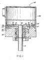
- Figure 1 is a cross-sectional view of an optical shaft encoder (10) fabricated in accordance with the invention. Although described in the context of an optical shaft encoder, the invention is equally applicable to shaft encoders which use magnetic, capacitive or conductive techniques.
- the optical shaft encoder (10) includes a shaft (11) which is journaled within a base (12) upon bearings (13, 14). Bearings (13, 14) are separated by a spacer (15). Shaft (11) is attached to a hub (16). The shaft and hub may be manufactured as an integral assembly. Hub (16) is preferably machined to have a precise flat upper surface upon which a code disk (17) is mounted.
- the code disk (17) is generally a thin transparent disk with a pattern of radially extending opaque lines thereon. The invention is well adapted for use with high resolution code disks having over 5 000 such lines.
- Base (12) preferably includes stand (18) upon which a substrate such as a printed circuit board (20) is mounted. Screws (19) secure the printed circuit board to the standoffs (18).
- a light source such as a light emitting diode (LED) (21) is attached to the base (12) by an adhesive (23).
- LED (21) Directly above LED (21) a photodetector (24) and a mask (25) are attached to printed circuit board (20) in a fashion hereinafter described in greater detail.
- Mask (25) is similar to a small segment of code disk (17) and includes a plurality of transparent areas and opaque lines. The mask covers photodetector (24) and is attached thereto by suitable trans parent adhesives.
- Code disk (17) rotates between LED (21) and photodetector (24).
- Base (12) is enclosed by a cover (26).
- the surfaces of code disk (17) and mask (25) must be maintained extremely parallel with an air gap of less than 0.125 mm for good accuracy.
- the mask must also be adjusted radially in relation to the code disk for proper output.
- the shaft (11) is used as a reference.
- the surface of the hub (the side which mates with code disk (17)) is machined perpendicular to the shaft axis. This insures that after the code disk is assembled on to hub (16), its surface is perpendicular to the axis of shaft (11). This, in turn, insures that when shaft (11) is rotated, the surface of the code disk does not wobble.
- printed circuit board (20) which includes the photodetector and mask assembly mounted thereon, is shown exaggerated at an angle to code disk (17) to illustrate that, in the invention, precise alignment of the printed circuit board (20) and the code disk (17) is not necessary.
- the leads (29) to the photo detector (24) and the mask (25) assembly are loosely inserted into printed circuit board (20), and the photodetector/mask assembly (25) is relatively movable under the printed circuit board assembly.
- the photodetector/mask assembly is pushed down toward the code disc surface with an appropriate shim or spacer between the assembly and the disk.
- Figure 3 is a plan view of printed circuit board (20), and Figure 4 is a side view of the assembly of Figure 3.
- Mask (25) contains two alignment marks (31, 32). Also, code disk (17) includes corresponding alignment marks (32). Two see-through holes (33, 34) in printed circuit board (20) enable the alignment marks (31, 32) to be positioned correctly beneath the printed circuit board. After correct positioning of the printed circuit board with the shim or spacer in place, photodetector leads (29) are soldered to printed circuit board (20) to secure the photodetector and mask in the properly aligned position.
- Base (12) can be a casting made with minimal secondary precision machining operations.
- the position of the code disk (17) with respect to the base (12) is not critical.
- the position and orientation of the printed circuit board(20)with respect to the code disk (17) or base (12) is also not critical, as shown in Figure 2.
- the relationship of these components make the optical shaft encoder (10) relatively easy and inexpensive to manufacture. After the photodetector and mask assembly is adjusted as discussed above, it can be fine adjusted if necessary at the final test by loosening the mounting screws (19) to the printed circuit board assembly (20).
- the invention has several advantages over prior art techniques for manufacturing an optical shaft encoder.
- a very tight gap between the code disk (17) and mask (25) is possible without the expensive precision machining operations on the related components.
- Prealignment features of the mask (25) with the code disk (17) prevent the use of guesswork and saves time.
- the mask (25) is fixed in relation to the photocell array or photodetector (24). This arrangement eliminates the cross talk problems between the data tracks inherent in the prior art.
Landscapes
- Engineering & Computer Science (AREA)
- Theoretical Computer Science (AREA)
- Optical Transform (AREA)
Applications Claiming Priority (2)
| Application Number | Priority Date | Filing Date | Title |
|---|---|---|---|
| US06/810,605 US4712005A (en) | 1985-12-19 | 1985-12-19 | Floating mask encoder with assembly spacer |
| US810605 | 1985-12-19 |
Publications (2)
| Publication Number | Publication Date |
|---|---|
| EP0228642A2 true EP0228642A2 (fr) | 1987-07-15 |
| EP0228642A3 EP0228642A3 (fr) | 1989-05-31 |
Family
ID=25204216
Family Applications (1)
| Application Number | Title | Priority Date | Filing Date |
|---|---|---|---|
| EP86117456A Withdrawn EP0228642A3 (fr) | 1985-12-19 | 1986-12-16 | Codeur à masque flottant |
Country Status (6)
| Country | Link |
|---|---|
| US (1) | US4712005A (fr) |
| EP (1) | EP0228642A3 (fr) |
| JP (1) | JPS62147315A (fr) |
| CA (1) | CA1261425A (fr) |
| DE (1) | DE3643164A1 (fr) |
| GB (1) | GB2184833B (fr) |
Families Citing this family (10)
| Publication number | Priority date | Publication date | Assignee | Title |
|---|---|---|---|---|
| JPH0275521U (fr) * | 1988-11-29 | 1990-06-08 | ||
| US5119128A (en) * | 1991-04-22 | 1992-06-02 | Xerox Corporation | Apparatus for generating timing pulses in an electrophotographic printing machine |
| US5923032A (en) * | 1997-05-02 | 1999-07-13 | Oak Industries Inc. | Interaligned component optical encoder with integral housing component locating studs and shelf |
| EP0932028A1 (fr) * | 1998-01-22 | 1999-07-28 | Primax Electronics Ltd | Capteur optique de rotation |
| US6166374A (en) * | 1998-11-04 | 2000-12-26 | Agilent Technologies, Inc. | Molded spring gap setting mechanism for optical encoders |
| US6600151B2 (en) | 2001-09-19 | 2003-07-29 | Lexmark International, Inc. | Optical encoder assembly with non-engageable encoder housing and receiver plate comprising a through hole and window |
| RU2213415C1 (ru) * | 2002-03-07 | 2003-09-27 | Закрытое акционерное общество завод "Измерон" | Фотоэлектрический преобразователь угла |
| JP5196437B2 (ja) * | 2008-12-26 | 2013-05-15 | ハイデンハイン株式会社 | ユニット型エンコーダの取り付け方法およびユニット型エンコーダ |
| US8947076B2 (en) | 2010-01-18 | 2015-02-03 | Bourns, Inc. | High resolution non-contacting multi-turn position sensor |
| CN112525234B (zh) * | 2020-11-19 | 2022-12-02 | 无锡麦德瑞光电科技有限公司 | 一种重载型无轴编码器 |
Family Cites Families (18)
| Publication number | Priority date | Publication date | Assignee | Title |
|---|---|---|---|---|
| US3524261A (en) * | 1968-08-19 | 1970-08-18 | Standard Gage Co Inc | Work supporting table for coaxial comparators |
| US3545088A (en) * | 1968-08-20 | 1970-12-08 | Johnson Co Gage | Gage setting device |
| US3900732A (en) * | 1974-04-15 | 1975-08-19 | Litton Systems Inc | Encoder disc mount and aligning tool |
| US3997782A (en) * | 1974-09-06 | 1976-12-14 | Dynapar Corporation | Rotary pulse transducer having stator sealing means |
| US4075478A (en) * | 1976-06-03 | 1978-02-21 | Litton Systems, Inc. | Floating head encoder |
| US4132890A (en) * | 1977-11-22 | 1979-01-02 | International Business Machines Corporation | Self adjusting tachometer |
| US4184071A (en) * | 1978-01-12 | 1980-01-15 | Electro-Craft Corporation | Modular encoder |
| US4193199A (en) * | 1978-05-15 | 1980-03-18 | Servo Products Company | Shaft position transducer |
| US4319134A (en) * | 1978-06-16 | 1982-03-09 | Sensor Technology, Inc. | Optical encoder |
| US4338517A (en) * | 1979-01-15 | 1982-07-06 | Perrine Warren L | Shaft rotation sensor |
| US4343992A (en) * | 1980-09-08 | 1982-08-10 | Blaser Anton J | V-Shaped centering fixture for optical encoders |
| US4345149A (en) * | 1980-09-08 | 1982-08-17 | Blaser Anton J | Disc-shaped centering fixture for optical encoders |
| US4375592A (en) * | 1980-12-19 | 1983-03-01 | International Business Machines Corporation | Incremental rotary encoder |
| JPS57136118A (en) * | 1981-02-17 | 1982-08-23 | Ricoh Co Ltd | Setting of phase difference in two sets of pulse trains of rotary encoder |
| DE3228507C2 (de) * | 1982-07-30 | 1986-11-13 | Dr. Johannes Heidenhain Gmbh, 8225 Traunreut | Winkelmeßeinrichtung |
| JPS59117915U (ja) * | 1983-01-29 | 1984-08-09 | トヨタ自動車株式会社 | 自動車のステアリングセンサ |
| US4556792A (en) * | 1983-05-12 | 1985-12-03 | Sumtak Corporation | Rotary encoder assembly and installation fixture |
| FR2567303B1 (fr) * | 1984-07-05 | 1986-12-26 | Mcb | Perfectionnements aux dispositifs de reglage des lecteurs pour capteurs de position angulaire |
-
1985
- 1985-12-19 US US06/810,605 patent/US4712005A/en not_active Expired - Fee Related
-
1986
- 1986-06-27 JP JP61152605A patent/JPS62147315A/ja active Pending
- 1986-10-08 CA CA000520093A patent/CA1261425A/fr not_active Expired
- 1986-12-15 DE DE19863643164 patent/DE3643164A1/de active Granted
- 1986-12-16 EP EP86117456A patent/EP0228642A3/fr not_active Withdrawn
- 1986-12-19 GB GB8630333A patent/GB2184833B/en not_active Expired - Fee Related
Also Published As
| Publication number | Publication date |
|---|---|
| GB2184833A (en) | 1987-07-01 |
| DE3643164C2 (fr) | 1989-05-24 |
| GB2184833B (en) | 1990-09-19 |
| CA1261425A (fr) | 1989-09-26 |
| DE3643164A1 (de) | 1987-07-02 |
| GB8630333D0 (en) | 1987-01-28 |
| US4712005A (en) | 1987-12-08 |
| EP0228642A3 (fr) | 1989-05-31 |
| JPS62147315A (ja) | 1987-07-01 |
Similar Documents
| Publication | Publication Date | Title |
|---|---|---|
| EP0003288B1 (fr) | Codeur incrémental modulaire à arbre rotatif, un gabarit de réglage, et une méthode de préalignement du stator d'un codeur optique | |
| CA1191959A (fr) | Codeur rotatif incrementiel | |
| CN102197283B (zh) | 安装模块化旋转编码器的方法和模块化旋转编码器 | |
| EP0228642A2 (fr) | Codeur à masque flottant | |
| EP0431976B1 (fr) | Appareil et méthode de codage optique | |
| US4075478A (en) | Floating head encoder | |
| EP0198926B1 (fr) | Codeur optique rotatif | |
| WO1986001289A1 (fr) | Codeur optique rotatif et procede d'assemblage | |
| US4285595A (en) | Modular encoder | |
| US4625109A (en) | Optical encoder apparatus and methods | |
| US4507110A (en) | Adjustable photosensor mounting arrangement for a centrifuge | |
| JP2003014497A (ja) | エンコーダ、およびエンコーダの取り付け方法 | |
| JPH10227661A (ja) | 回転変位情報検出装置 | |
| JPH10132611A (ja) | 回転変位情報検出装置 | |
| KR102082287B1 (ko) | 엔코더 정렬 장치 | |
| JPH0754811Y2 (ja) | エンコーダ | |
| JP3472034B2 (ja) | 回転変位情報検出装置 | |
| CN216390746U (zh) | 电机装置 | |
| JPH0442729Y2 (fr) | ||
| EP0633561A2 (fr) | Appareil à têtes magnétiques rotatives à canaux multiples | |
| JP2521446Y2 (ja) | エンコ−ダ一体型エアスピンドル装置 | |
| JPH0250366A (ja) | ディスク装置 | |
| JPS63204115A (ja) | 磁気エンコ−ダ | |
| JPH10253396A (ja) | ロータリエンコーダ | |
| CN117146872A (zh) | 一种偏心盘轴角编码器 |
Legal Events
| Date | Code | Title | Description |
|---|---|---|---|
| PUAI | Public reference made under article 153(3) epc to a published international application that has entered the european phase |
Free format text: ORIGINAL CODE: 0009012 |
|
| AK | Designated contracting states |
Kind code of ref document: A2 Designated state(s): CH DE FR GB IT LI SE |
|
| PUAL | Search report despatched |
Free format text: ORIGINAL CODE: 0009013 |
|
| AK | Designated contracting states |
Kind code of ref document: A3 Designated state(s): CH DE FR GB IT LI SE |
|
| 17P | Request for examination filed |
Effective date: 19891104 |
|
| RAP1 | Party data changed (applicant data changed or rights of an application transferred) |
Owner name: KOLLMORGEN CORPORATION |
|
| 17Q | First examination report despatched |
Effective date: 19900625 |
|
| STAA | Information on the status of an ep patent application or granted ep patent |
Free format text: STATUS: THE APPLICATION HAS BEEN WITHDRAWN |
|
| 18W | Application withdrawn |
Withdrawal date: 19910803 |
|
| R18W | Application withdrawn (corrected) |
Effective date: 19910803 |
|
| RIN1 | Information on inventor provided before grant (corrected) |
Inventor name: SAVLA, LALIT J. |